2006 LAND ROVER FRELANDER 2 key
[x] Cancel search: keyPage 1092 of 3229
Publi s hed: 11-May-2011
Starting System - TD4 2.2L Diesel - Start Control Unit
Removal and Inst all ati on
Removal
1. NOTE: Thi s s tep must be performed i f replacing t he s tart cont rol
unit .
• NOTE: Make s ure that all keys (remote cont rol hands ets ) are
pres ent when performi ng thi s procedure.
Us ing t he Land Rover approved diagnost ic equipment , int errogat e
t he s tart cont rol uni t and upload t he s tored dat a.
1.
Make t he SRS s ys t em s afe.
Refer t o: Standard W orks hop Pract ices (100-00 General Informat ion,
Des cript ion and Operat ion).
2.
Remove t he dri ver l ower ai r bag.
Refer t o: Dri ver Lower Air Bag Module (501-20B Supplemental
Res traint Sys t em, Removal and Inst all at ion).
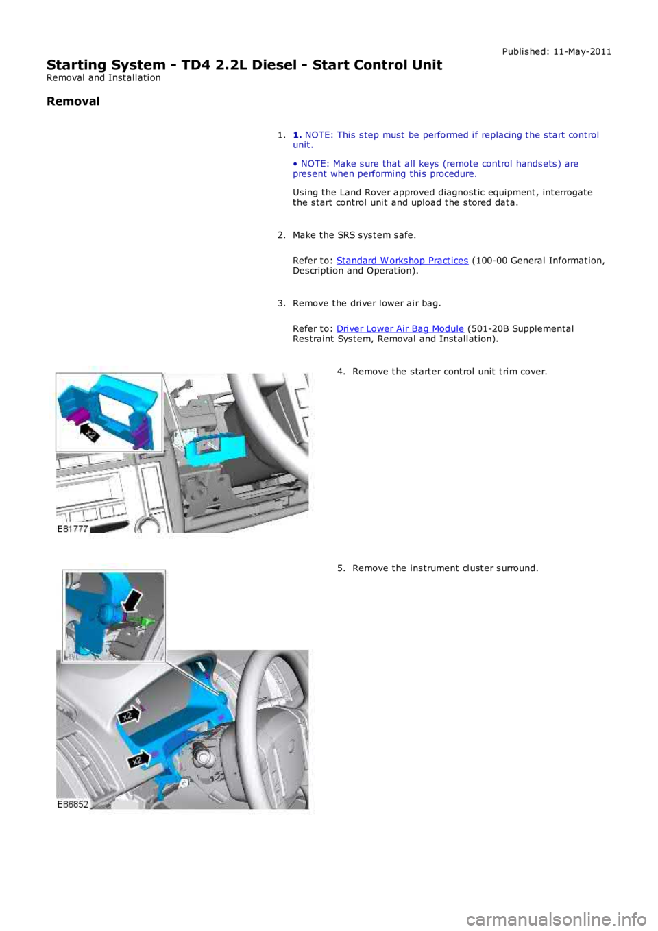
3. Remove t he s tart er cont rol unit t ri m cover.
4. Remove t he ins trument cl ust er s urround.
5.
Page 1114 of 3229
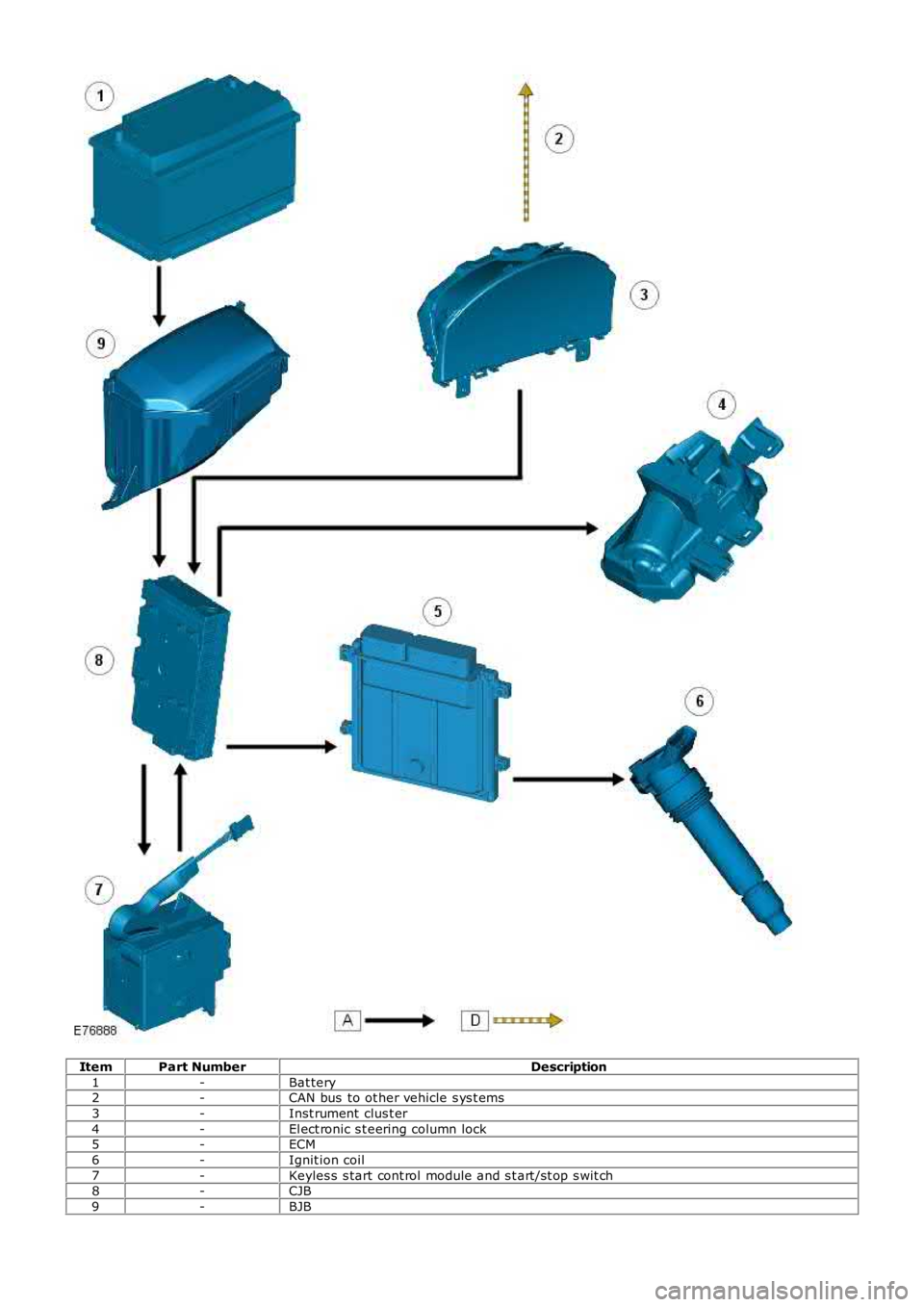
ItemPart NumberDescription
1-Bat tery2-CAN bus to ot her vehicle s ys t ems
3-Inst rument clus t er
4-El ect ronic s t eering column lock5-ECM
6-Ignit ion coil
7-Keyles s s tart cont rol module and s t art /s t op s wit ch8-CJB
9-BJB
Page 1158 of 3229
In thi s posi ti on, t he puls ati ons are onl y det ermined by t he s hort int ake pi pe's geometry.
The t ot al vol ume for al l cyli nders now acces s ibl e is necess ary to have s uffici ent acces s t o air.
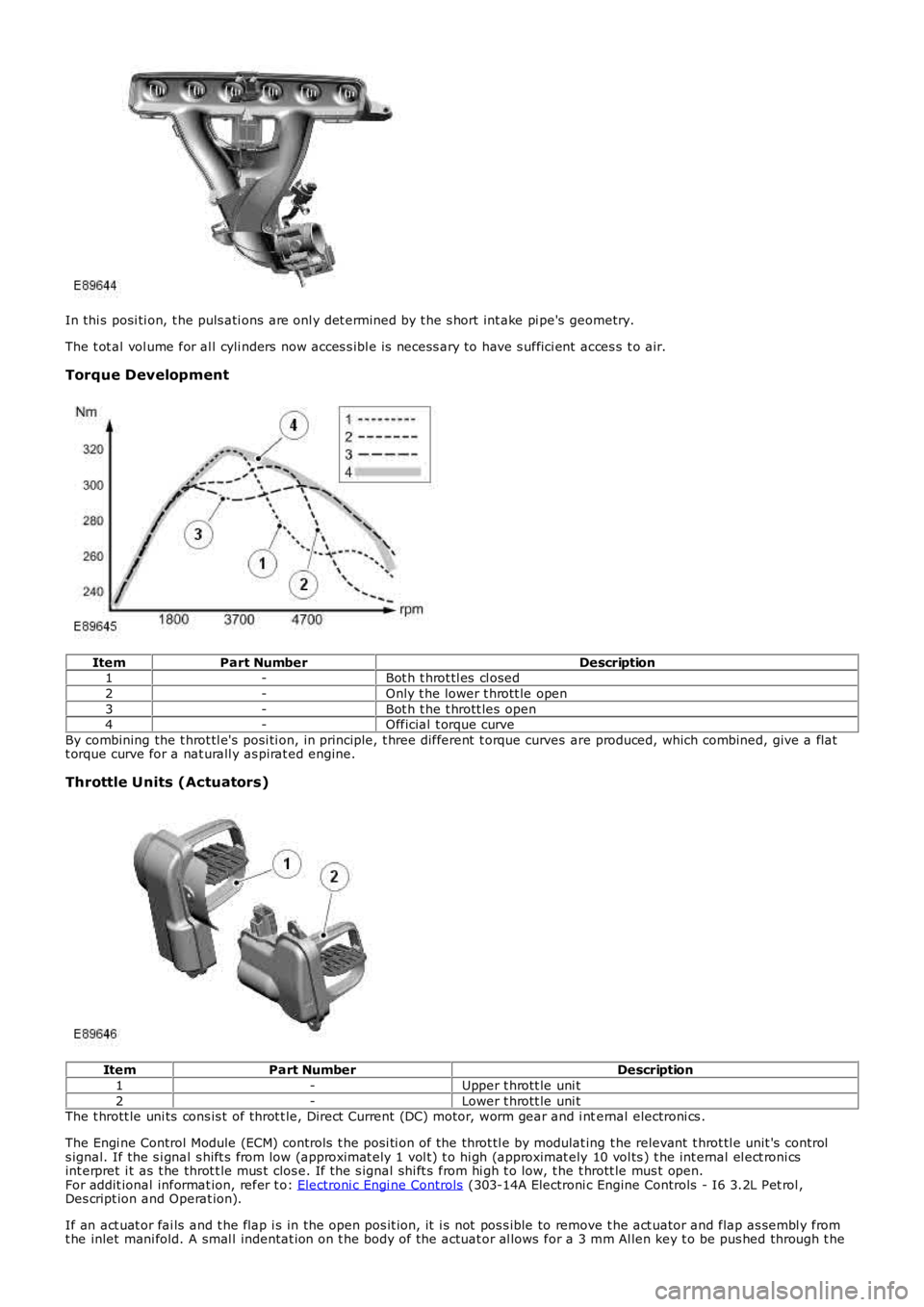
Torque Development
ItemPart NumberDescription1-Bot h t hrot tl es cl osed
2-Only t he lower t hrott le open
3-Bot h t he t hrott les open4-Official t orque curve
By combining the t hrot tl e's posi ti on, in principle, t hree different t orque curves are produced, which combined, give a flatt orque curve for a nat urall y as pirat ed engine.
Throttle Units (Actuators)
ItemPart NumberDescription
1-Upper t hrott le uni t
2-Lower t hrott le uni tThe t hrott le uni ts cons is t of throt t le, Direct Current (DC) motor, worm gear and i nternal electroni cs .
The Engi ne Control Module (ECM) controls t he posi ti on of the throt tl e by modulat ing t he relevant t hrot tl e unit 's controls ignal. If the s i gnal s hift s from low (approximat ely 1 vol t) t o hi gh (approximat ely 10 vol ts ) t he int ernal el ect roni csint erpret i t as t he throt t le mus t clos e. If t he s ignal shi ft s from hi gh t o low, t he t hrott le mus t open.For addit ional informat ion, refer t o: Electroni c Engi ne Controls (303-14A Electroni c Engine Controls - I6 3.2L Pet rol ,Des cript ion and Operat ion).
If an act uat or fai ls and t he flap i s in the open pos it ion, it i s not pos s ible to remove t he act uator and flap as sembl y fromt he inlet mani fold. A smal l indentat ion on t he body of the actuat or al lows for a 3 mm Al len key t o be pus hed through t he
Page 1159 of 3229

t hi n membrane wall of the act uat or hous ing. The All en key can be engaged i n t he spi ndl e of t he act uat or mot or, whichall ows the flap to be turned to the clos ed pos it ion and cons equent ly the actuat or and flap as s embly can t hen be removedfrom the i ntake manifold.
Page 1213 of 3229
The inject ors recei ve a fus ed bat tery vol tage s upply via the main relay. The ECM operates t he i nject ors by groundi ngs olenoi d valves in the injector. W hen t he ground is appl ied t he s olenoi d valve operat es and the injector s prays pres s uri zedfuel from the fuel rail i nt o t he cyl inder int ake ports . The amount of fuel injected and the t iming of t he inject ion peri od iscont rol led by t he ECM us ing dat a from other s ens ors .
The ECM can monit or the injector operat ion by moni toring t he ground l ine from the i njector. Each i njector can be diagnosedby t he ECM and faul t codes s t ored. The codes can be read us ing a Land Rover approved diagnos t ic s ys tem.
Variable Intake System (VIS)
The VIS changes the length of t he inl et manifol d us ing t wo ECM controll ed act uators which move flaps t o cont rol t he airfl ow. The act uators operate s i ngul arly or t oget her to adjust t he l engt h of the inlet t ract.
Us ing an 'H' bridge, the intake and pl enum act uator's i nt ernal electroni cs changes the act uat or motor's polarit y andt herefore the flap pos it ion. At each fl ap pos i ti on change, the DC act uator mot or i s powered for approxi matel y 0.5 seconds .The worm gear des ign ens ures t hat the flap remains in t he desi red pos it ion, even when the el ect ri c mot ors are notpowered.
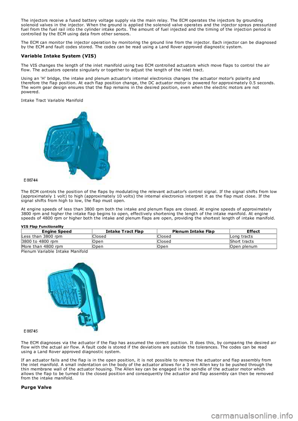
Int ake Tract Variabl e Manifol d
The ECM controls t he posi ti on of the flaps by modul at ing the relevant act uat or's cont rol s ignal. If the s ignal s hi ft s from low(approxi mately 1 volt ) to hi gh (approxi matel y 10 volt s) t he i nt ernal electroni cs interpret i t as the flap must cl os e. If thes ignal shi ft s from hi gh to low, t he fl ap mus t open.
At engi ne s peeds of l es s t han 3800 rpm both the i ntake and plenum flaps are clos ed. At engine s peeds of approxi matel y3800 rpm and higher the i ntake flap begins t o open, effecti vel y s hort eni ng the length of t he int ake manifol d. At engi nes peeds of 4800 rpm or higher bot h t he int ake and plenum flaps are open, providi ng the short es t length of i ntake manifold.
VIS Flap Functionality
Engine SpeedIntake T ract FlapPlenum Intake FlapEffectLess than 3800 rpmClos edClos edLong tract s
3800 t o 4800 rpmOpenClos edShort t racts
More than 4800 rpmOpenOpenOpen plenumPlenum Variable Int ake Mani fold
The ECM di agnos es vi a t he act uator i f the flap has as s umed the correct pos i ti on. It does this , by compari ng the des ired airfl ow wi th the act ual air flow. A fault code is st ored i f the deviat ions are outs ide t he t olerances. The codes can be readus ing a Land Rover approved di agnos ti c s ys t em.
If an act uat or fai ls and t he flap i s in the open pos it ion, it i s not pos s ible to remove t he act uator and flap as sembl y fromt he inlet mani fold. A smal l indentat ion on t he body of the actuat or al lows for a 3 mm Al len key t o be pus hed through t het hi n membrane wall of the act uat or hous ing. The All en key can be engaged i n t he spi ndl e of t he act uat or mot or whi chall ows the flap to be turned to the clos ed pos it ion and cons equent ly the actuat or and flap as s embly can t hen be removedfrom the i ntake manifold.
Purge Valve
Page 1374 of 3229
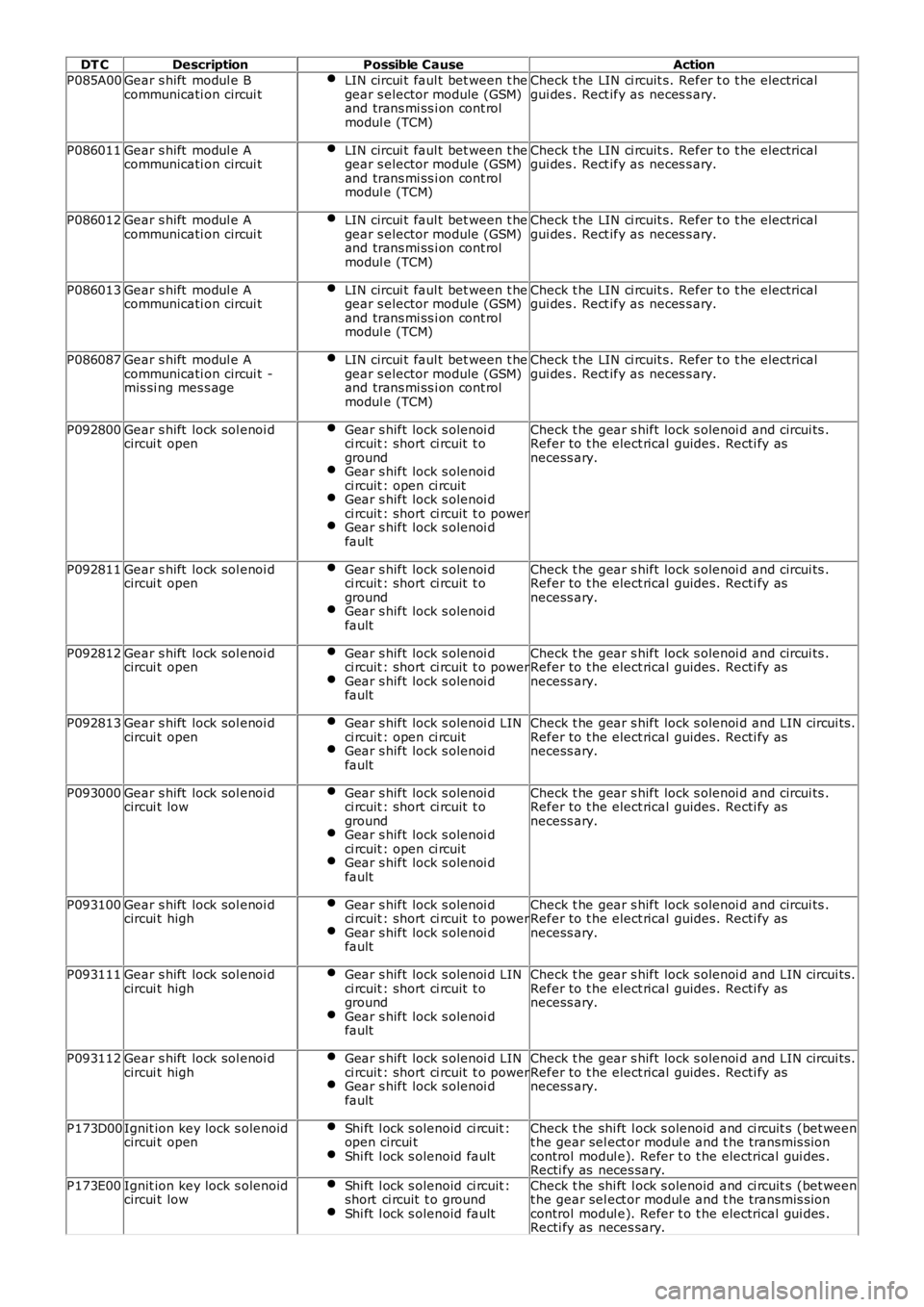
DT CDescriptionPossible CauseAction
P085A00Gear s hift modul e Bcommunicati on circui tLIN circui t faul t bet ween t hegear s elector module (GSM)and trans mi ss i on cont rolmodul e (TCM)
Check t he LIN ci rcuit s. Refer t o t he electricalgui des . Rect ify as neces s ary.
P086011Gear s hift modul e Acommunicati on circui tLIN circui t faul t bet ween t hegear s elector module (GSM)and trans mi ss i on cont rolmodul e (TCM)
Check t he LIN ci rcuit s. Refer t o t he electricalgui des . Rect ify as neces s ary.
P086012Gear s hift modul e Acommunicati on circui tLIN circui t faul t bet ween t hegear s elector module (GSM)and trans mi ss i on cont rolmodul e (TCM)
Check t he LIN ci rcuit s. Refer t o t he electricalgui des . Rect ify as neces s ary.
P086013Gear s hift modul e Acommunicati on circui tLIN circui t faul t bet ween t hegear s elector module (GSM)and trans mi ss i on cont rolmodul e (TCM)
Check t he LIN ci rcuit s. Refer t o t he electricalgui des . Rect ify as neces s ary.
P086087Gear s hift modul e Acommunicati on circui t -mis si ng mes s age
LIN circui t faul t bet ween t hegear s elector module (GSM)and trans mi ss i on cont rolmodul e (TCM)
Check t he LIN ci rcuit s. Refer t o t he electricalgui des . Rect ify as neces s ary.
P092800Gear s hift lock sol enoi dcircui t openGear s hift lock s olenoi dci rcuit : short ci rcuit t ogroundGear s hift lock s olenoi dci rcuit : open ci rcuitGear s hift lock s olenoi dci rcuit : short ci rcuit t o powerGear s hift lock s olenoi dfault
Check t he gear s hift lock s olenoi d and circui ts .Refer to t he elect rical guides. Recti fy asnecess ary.
P092811Gear s hift lock sol enoi dcircui t openGear s hift lock s olenoi dci rcuit : short ci rcuit t ogroundGear s hift lock s olenoi dfault
Check t he gear s hift lock s olenoi d and circui ts .Refer to t he elect rical guides. Recti fy asnecess ary.
P092812Gear s hift lock sol enoi dcircui t openGear s hift lock s olenoi dci rcuit : short ci rcuit t o powerGear s hift lock s olenoi dfault
Check t he gear s hift lock s olenoi d and circui ts .Refer to t he elect rical guides. Recti fy asnecess ary.
P092813Gear s hift lock sol enoi dcircui t openGear s hift lock s olenoi d LINci rcuit : open ci rcuitGear s hift lock s olenoi dfault
Check t he gear s hift lock s olenoi d and LIN circui ts .Refer to t he elect rical guides. Recti fy asnecess ary.
P093000Gear s hift lock sol enoi dcircui t lowGear s hift lock s olenoi dci rcuit : short ci rcuit t ogroundGear s hift lock s olenoi dci rcuit : open ci rcuitGear s hift lock s olenoi dfault
Check t he gear s hift lock s olenoi d and circui ts .Refer to t he elect rical guides. Recti fy asnecess ary.
P093100Gear s hift lock sol enoi dcircui t highGear s hift lock s olenoi dci rcuit : short ci rcuit t o powerGear s hift lock s olenoi dfault
Check t he gear s hift lock s olenoi d and circui ts .Refer to t he elect rical guides. Recti fy asnecess ary.
P093111Gear s hift lock sol enoi dcircui t highGear s hift lock s olenoi d LINci rcuit : short ci rcuit t ogroundGear s hift lock s olenoi dfault
Check t he gear s hift lock s olenoi d and LIN circui ts .Refer to t he elect rical guides. Recti fy asnecess ary.
P093112Gear s hift lock sol enoi dcircui t highGear s hift lock s olenoi d LINci rcuit : short ci rcuit t o powerGear s hift lock s olenoi dfault
Check t he gear s hift lock s olenoi d and LIN circui ts .Refer to t he elect rical guides. Recti fy asnecess ary.
P173D00Ignit ion key lock s olenoidcircui t openShi ft l ock s olenoid ci rcuit :open circui tShi ft l ock s olenoid fault
Check t he shi ft l ock s olenoid and ci rcuit s (bet weent he gear sel ect or modul e and t he transmis s ioncontrol modul e). Refer t o t he electrical gui des .Recti fy as neces sary.
P173E00Ignit ion key lock s olenoidcircui t lowShi ft l ock s olenoid ci rcuit :short ci rcuit t o groundShi ft l ock s olenoid fault
Check t he shi ft l ock s olenoid and ci rcuit s (bet weent he gear sel ect or modul e and t he transmis s ioncontrol modul e). Refer t o t he electrical gui des .Recti fy as neces sary.
Page 1375 of 3229

DT CDescriptionPossible CauseAction
P173F00Ignit ion key lock s olenoidcircui t highShi ft l ock s olenoid ci rcuit :short ci rcuit t o powerShi ft l ock s olenoid fault
Check t he shi ft l ock s olenoid and ci rcuit s (bet weent he gear sel ect or modul e and t he transmis s ioncontrol modul e). Refer t o t he electrical gui des .Recti fy as neces sary.U210511Swi tch Pack Signal "A"Shi ft Lock pos i ti on si gnalci rcuit - s hort t o ground,open circui t
Refer to el ect ri cal circui t diagrams and check shi ftl ock pos it ion si gnal circui t for s hort t o ground,open circui t
U210512Swi tch Pack Signal "A"Shi ft Lock pos i ti on si gnalci rcuit - s hort t o powerRefer to el ect ri cal circui t diagrams and check shi ftl ock pos it ion si gnal circui t for s hort t o power
Page 1718 of 3229
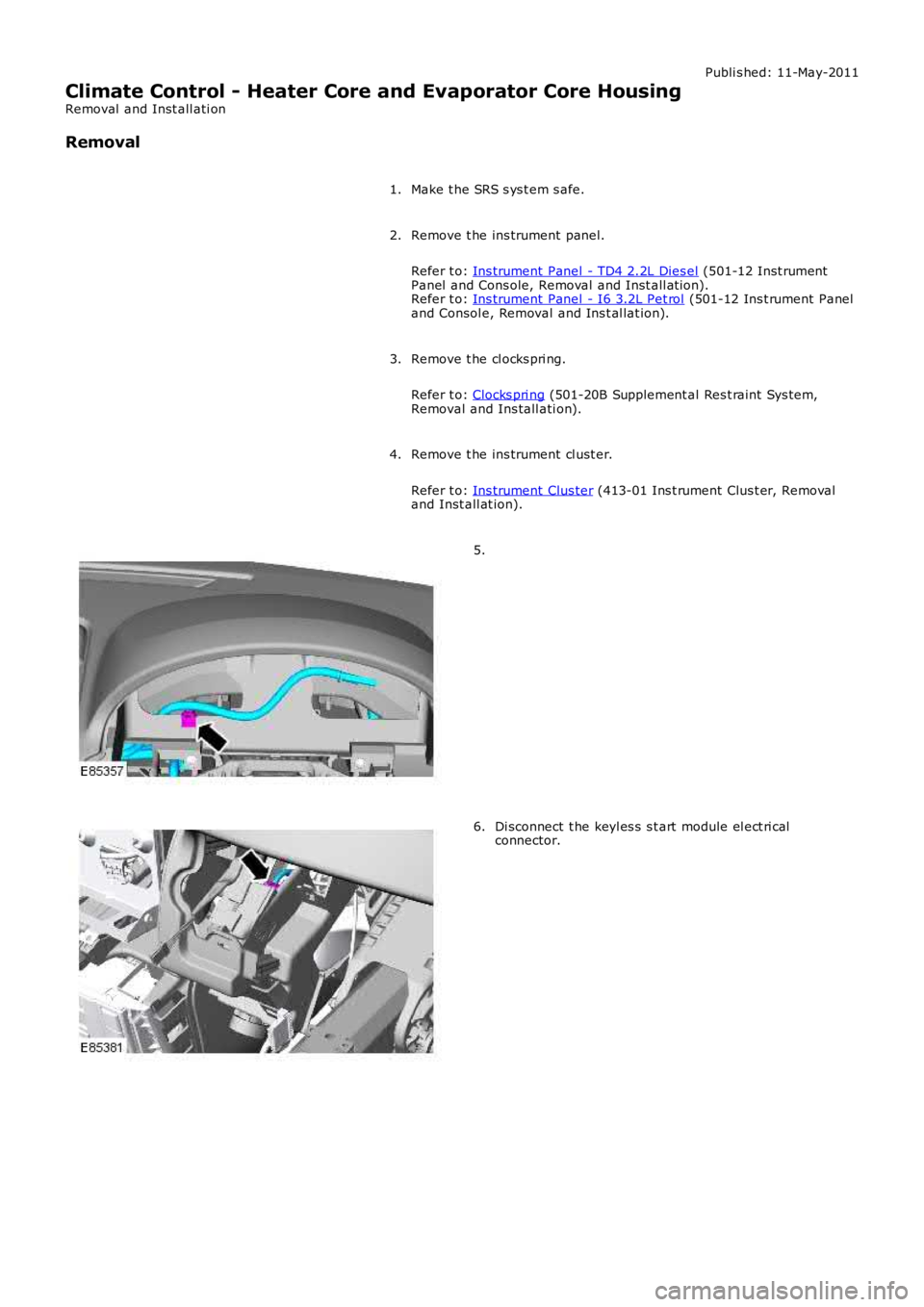
Publi s hed: 11-May-2011
Climate Control - Heater Core and Evaporator Core Housing
Removal and Inst all ati on
Removal
Make t he SRS s ys t em s afe.1.
Remove t he ins trument panel.
Refer t o: Ins trument Panel - TD4 2.2L Dies el (501-12 Inst rumentPanel and Cons ole, Removal and Inst all at ion).Refer t o: Ins trument Panel - I6 3.2L Pet rol (501-12 Ins t rument Paneland Consol e, Removal and Ins t al lat ion).
2.
Remove t he cl ocks pri ng.
Refer t o: Clocks pri ng (501-20B Supplement al Res t raint Sys tem,Removal and Ins tall ati on).
3.
Remove t he ins trument cl ust er.
Refer t o: Ins trument Clus ter (413-01 Ins t rument Clus t er, Removaland Inst all at ion).
4.
5.
Di sconnect t he keyl es s s t art module el ect ri calconnector.6.