2006 LAND ROVER FRELANDER 2 key
[x] Cancel search: keyPage 2187 of 3229
Publi s hed: 11-May-2011
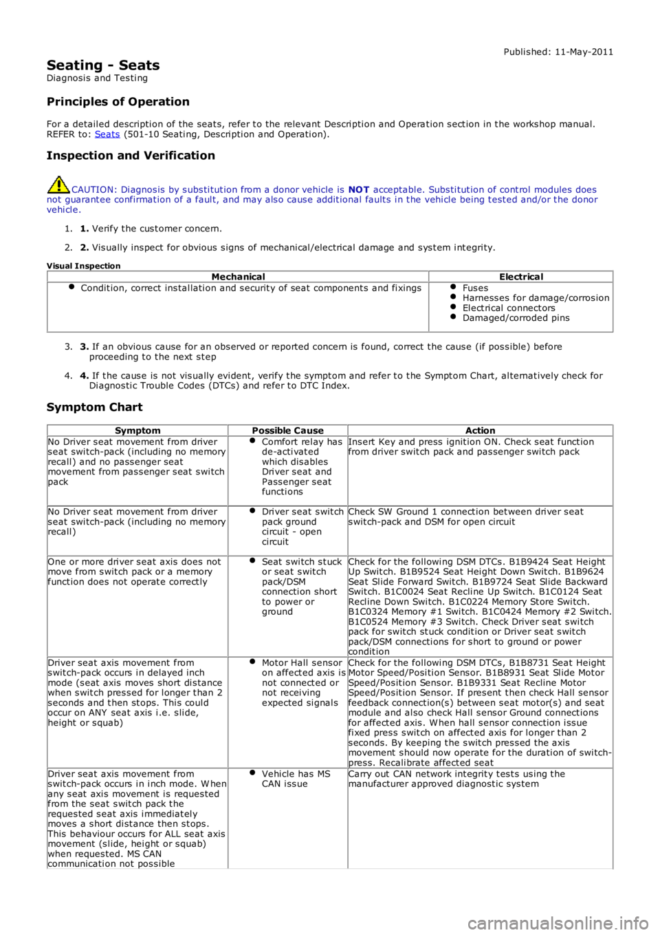
Seating - Seats
Diagnosi s and Tes ti ng
Principles of Operation
For a detail ed descripti on of the seat s, refer t o the relevant Descri pti on and Opera t ion s ect ion in t he works hop manual.
REFER to: Seats (501-10 Seati ng, Des cri pti on and Operati on).
Inspection and Verification CAUTION: Di agnos is by s ubs ti tut ion from a donor vehicle is
NO T acceptabl e. Subs ti tut ion of cont rol modules does
not guarant ee confirmat ion of a faul t, and may als o caus e addit ional fault s i n t he v ehi cl e being t est ed and/or t he donor
vehi cl e.
1. Verify t he cus t omer concern.
1.
2. Vis ually ins pect for obvious s igns of mechani cal /elect rical damage and s ys t em i nt egr i ty.
2.
Visual Inspection Mechanical Electrical
Condit ion, correct ins tal lati on and s ecurit y of seat component s and fi xings Fus es
Harness es for damage/corros ion
El ect ri cal connect ors
Damaged/corroded pins
3.
If an obvious cause for an obs erved or report ed concern is found, correct t he caus e (if pos s ible) before
proceeding t o t he next s t ep
3.
4. If t he caus e is not vis ually evi dent , verify t he sympt om and refer t o t he Sympt om Ch art, al ternat ively check for
Di agnos ti c Trouble Codes (DTCs) and refer t o DTC Index.
4.
Symptom Chart Symptom Possible Cause Action
No Driver s eat movement from driver
s eat swi tch-pack (including no memory
recall ) and no pass enger seat
movement from pas s enger s eat s wi tch
pack Comfort rel ay has
de-acti vat ed
which dis ables
Dri ver s eat and
Pass enger s eat
functi ons Ins ert Key and press ignit ion ON. Check s eat funct ion
from driver swit ch pack and pas senger swi tch pack
No Driver s eat movement from driver
s eat swi tch-pack (including no memory
recall ) Dri ver s eat s wit ch
pack ground
circuit - open
circuit Check SW Ground 1 connect ion bet ween dri ver s eat
s wit ch-pack and DSM for open circuit
One or more dri ver s eat axis does not
move from s wit ch pack or a memory
funct ion does not operat e correct ly Seat s wi tch s t uck
or seat s wit ch
pack/DSM
connecti on short
to power or
ground Check for the foll owi ng DSM DTCs . B1B9424 Seat Height
Up Swit ch. B1B9524 Seat Hei ght Down Swit ch. B1B9624
Seat Sl ide Forward Swit ch. B1B9724 Seat Sl ide Backward
Swit ch. B1C0024 Seat Recli ne Up Swit ch. B1C0124 Seat
Recl ine Down Swi tch. B1C0224 Memory St ore Swi tch.
B1C0324 Memory #1 Swi tch. B1C0424 Memory #2 Swi tch.
B1C0524 Memory #3 Swi tch. Check Driver s eat s wi tch
pack for swit ch st uck condit ion or Driver seat s wit ch
pack/DSM connecti ons for s hort to ground or power
condit ion
Driver seat axis movement from
s wit ch-pack occurs i n delayed inch
mode (s eat axis moves short di s tance
when s wit ch pres s ed for l onger t han 2
s econds and t hen st ops. Thi s coul d
occur on ANY seat axis i .e. s li de,
height or s quab) Motor Hall s ens or
on affect ed axis i s
not connect ed or
not recei ving
expected si gnal s Check for the foll owi ng DSM DTCs , B1B8731 Seat Height
Motor Speed/Posi ti on Sens or. B1B8931 Seat Sl ide Mot or
Speed/Pos it ion Sens or. B1B9331 Seat Recline Motor
Speed/Pos it ion Sens or. If pres ent t hen check Hall s ens or
feedback connect ion(s ) between s eat mot or(s) and s eat
module and al so check Hall s ens or Ground connect ions
for affect ed axis . W hen hall s ens or connect ion i ss ue
fi xed pres s s wit ch on affect ed axi s for l onger t han 2
s econds. By keeping t he s wit ch pres s ed the axis
movement s hould now operate for the durati on of swi tch-
pres s. Recali brate affect ed seat
Driver seat axis movement from
s wit ch-pack occurs i n i nch mode. W hen
any s eat axi s movement i s reques ted
from the s eat s wit ch pack t he
reques ted s eat axis i mmediat el y
moves a s hort di st ance then s t ops .
This behaviour occurs for ALL seat axis
movement (s l ide, hei ght or s quab)
when reques ted. MS CAN
communicati on not pos s ible Vehi cle has MS
CAN i ss ue Carry out CAN network int egrit y t es t s us ing t he
manufacturer approved diagnost ic sys tem
Page 2193 of 3229
Publi s hed: 11-May-2011
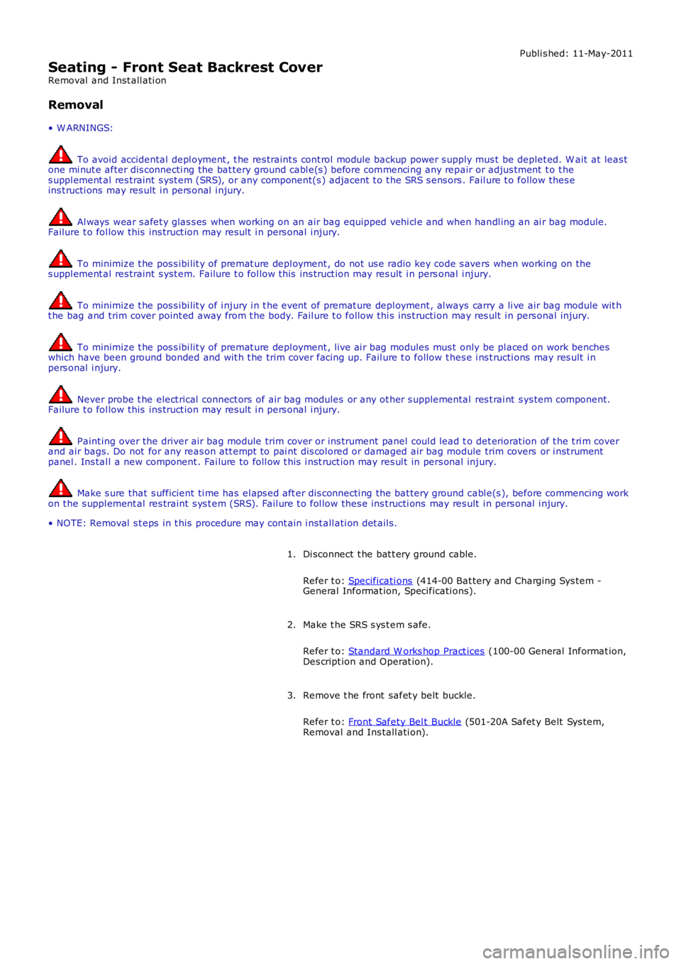
Seating - Front Seat Backrest Cover
Removal and Inst all ati on
Removal
• W ARNINGS:
To avoid accidental depl oyment , t he res traint s cont rol module backup power s upply mus t be deplet ed. W ait at leas tone mi nut e after dis connecti ng the bat tery ground cabl e(s ) before commenci ng any repair or adjus tment t o t hes uppl ement al res traint s yst em (SRS), or any component(s ) adjacent t o t he SRS s ens ors. Fail ure t o follow thes eins t ructi ons may res ult i n pers onal i njury.
Al ways wear s afet y glas s es when working on an air bag equipped vehi cl e and when handl ing an ai r bag module.Failure t o fol low this ins truct ion may res ult i n pers onal i njury.
To minimize t he pos s ibi lit y of premat ure depl oyment , do not us e radio key code s avers when working on thes uppl ement al res traint s yst em. Failure t o fol low this ins truct ion may res ult i n personal i njury.
To minimize t he pos s ibi lit y of i njury i n t he event of premat ure depl oyment , al ways carry a li ve air bag module wit ht he bag and trim cover point ed away from t he body. Fail ure t o follow thi s ins t ructi on may res ult i n pers onal injury.
To minimize t he pos s ibi lit y of premat ure depl oyment , live ai r bag modules mus t only be pl aced on work bencheswhich have been ground bonded and wit h t he trim cover facing up. Fail ure t o follow thes e i ns t ructi ons may res ult i npers onal i njury.
Never probe t he elect rical connect ors of air bag modules or any ot her s upplemental res t rai nt s ys tem component.Failure t o fol low this ins truct ion may res ult i n pers onal i njury.
Paint ing over the driver air bag module trim cover or ins trument panel coul d lead to det eriorat ion of t he t ri m coverand air bags. Do not for any reas on att empt to pai nt dis col ored or damaged air bag module trim covers or i nst rumentpanel . Ins tal l a new component . Fai lure to foll ow t his i nst ruct ion may res ul t in pers onal injury.
Make s ure that s ufficient ti me has el aps ed aft er dis connecti ng the bat tery ground cabl e(s ), before commencing workon t he s uppl ement al res traint s ys t em (SRS). Fail ure t o fol low thes e ins t ructi ons may res ult i n pers onal i njury.
• NOTE: Removal s t eps in t his procedure may cont ain i nst all ati on det ail s.
Di sconnect t he bat t ery ground cable.
Refer t o: Specificati ons (414-00 Bat tery and Charging Sys tem -General Informat ion, Specificati ons).
1.
Make t he SRS s ys t em s afe.
Refer t o: Standard W orks hop Pract ices (100-00 General Informat ion,Des cript ion and Operat ion).
2.
Remove t he front safet y belt buckle.
Refer t o: Front Safety Bel t Buckle (501-20A Safet y Belt Sys tem,Removal and Ins tall ati on).
3.
Page 2281 of 3229
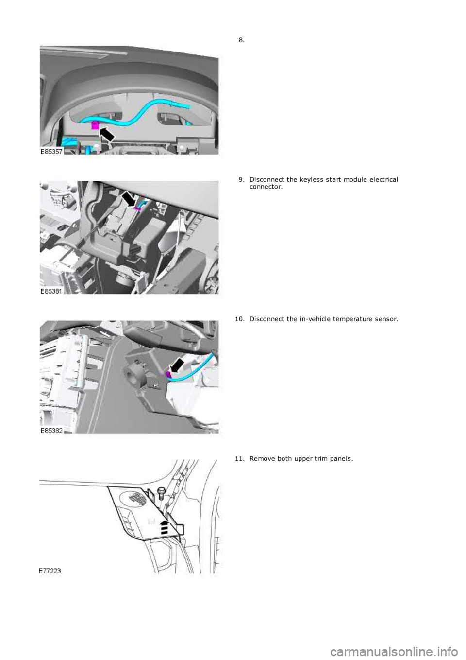
8.
Di sconnect t he keyl es s s t art module el ect ri calconnector.9.
Di sconnect t he in-vehicl e temperature s ens or.10.
Remove both upper t rim panels .11.
Page 2290 of 3229
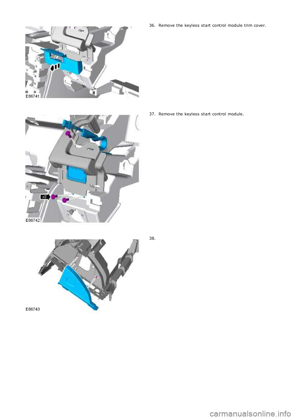
Remove t he keyl es s s t art cont rol module trim cover.36.
Remove t he keyl es s s t art cont rol module.37.
38.
Page 2292 of 3229
Inst all t he cl ips .
1.
Inst all t he regis t er ducti ng.
2.
Inst all t he winds hield defros ter duct.
3.
Inst all t he pas s enger s ide regis t er.
4.
Inst all t he dri ver s ide regis ter.
5.
Inst all t he dri ver s ide i nst rument panel end trim panel .
6.
Inst all t he keyl es s s t art cont rol module.
7.
Inst all t he keyl es s s t art cont rol module trim cover.
8.
Inst all t he in-vehicl e temperature s ens or.
9.
Inst all t he winds hield defros ter t ri m panel.
10.
Inst all t he glove compartment s upport panel s .
11.
Inst all t he glove compartment l id hi nges .
12.
Inst all t he glove compartment l amp.
13.
Inst all t he pas s enger ai r bag modul e.
T orque: 10 Nm 14.
Inst all t he glove compartment s t ri ker reinforcement panel.
15.
W it h ass i st ance, i ns t all the ins trument panel upper s ect ion.
16.
Secure t he wiring harnes s cli p t o t he pas s enger s ide of t he
i ns t rument panel upper secti on.
17.
Secure t he 2 wi ri ng harness cl ips t o t he winds hield defros ter duct
and connect the sunload s ens or.
18.
W it h ass i st ance, s ecure t he ins trument panel upper s ecti on.
19.
Inst all t he winds hield defros ter outer finis hers .
20.
Connect t he pass enger ai r bag modul e electrical connect ors .
21.
Connect t he glove compart ment lamp el ect ri cal connector.
22.
Secure t he pass enger ai r bag modul e and glove compart ment lamp
wi ri ng harness .
23.
Inst all t he glove compartment .
24.
Page 2293 of 3229
Refer t o: Glove Compart ment (501-12 Ins trument Panel andConsol e, Removal and Ins t al lat ion).
Inst all t he pas s enger s ide ins trument panel end trim panel .25.
Secure t he wiring harnes s s upport bracket .26.
Secure t he wiring harnes s t o t he cent er of the i nst rument panelupper s ecti on.27.
Inst all t he cl imat e control as s embly.28.
Inst all t he audi o unit .29.
Inst all t he cent er speaker.30.
Inst all t he video dis play.
Refer t o: Video Dis play (415-01 Informati on and Entert ainmentSyst em, Removal and Ins tall ati on).
31.
Inst all t he fl oor consol e.
Refer t o: Fl oor Cons ole (501-12 Inst rument Panel and Cons ole,Removal and Ins tall ati on).
32.
Inst all t he fl oor consol e extens ions.33.
Inst all both ins trument panel s peakers .34.
Inst all both upper t rim panels .35.
Connect t he in-vehi cl e t emperature s ens or electrical connect or.36.
Connect t he keyl es s s t art module elect rical connect or.37.
Secure t he ins trument cl ust er wiring harnes s cli p.38.
Inst all t he ins trument cl ust er.
Refer t o: Ins trument Clus ter (413-01 Ins t rument Clus t er, Removaland Inst all at ion).
39.
Inst all t he cl ocks pri ng.
Refer t o: Clocks pri ng (501-20B Supplement al Res t raint Sys tem,Removal and Ins tall ati on).
40.
Inst all both cowl s ide t rim panels .
Refer t o: Cowl Si de Tri m Panel (501-05 Interior Tri m andOrnament ati on, Removal and Ins tal lat ion).
41.
Secure both scuff pl ate t rim panels .42.
Inst all t he A-pi llar center t rim panels .43.
Page 2309 of 3229
The lock and double lock mot ors control the engagement of t he door lat ches with t he releas e cables to lock and unlock thevehicle. W hen t he vehicl e i s l ocked, the lock mot ors disengage the door latches from the exterior rel ease cabl es . W hen t hevehicle is doubl e l ocked, the double lock mot ors als o dis engage t he door l at ches from t he interior rel ease cables . W hen t hevehicle is s ubsequentl y unl ocked, the int erior and ext eri or releas e cables are re-engaged wi th the door latches.
Al l the door interior release handl es incorporate a locking button. W hen a front door central locking but ton is press ed/pulled,all the vehi cle doors will cent rally lock/unlock. W hen a rear door locki ng butt on is press ed/pull ed, t he locking button will onlylock/unlock the activat ed rear door.
W hen the door locki ng butt on is press ed, t he interior release cable is pus hed and causes the exterior releas e cabl e t o bedis engaged from t he door l at ch. On the rear doors, pres sing the locki ng butt on will also disengage the interior handl e fromthe i nt eri or releas e cable.
W hen the door locki ng butt on is pul led away from t he door, the door int erior releas e handle is re-engaged wit h the i nt eri orrelease cable. As the i nt eri or releas e cable is re-engaged it i s pulled, caus ing the door lat ch to re-engage with t he ext eri orrelease cable.
Rear Door Child Locks
The rear door latches i ncorporat e child locks that provide addit ional rear occupancy safety. The chi ld locks are manuallyoperat ed us ing the emergency key blade within the remote hands et . Setti ng the child lock t o t he l ocked pos it ion wil ldis engage the door lat ch interior rel ease cable from the door latch, and prevent opening of the rear door us ing t he interiorrelease handl e.
For further informati on on chi ld locks, refer to t he Owners Handbook.
Door Ajar Switch
An ajar s wi tch i s i ns talled in each door l atch and is hardwi red t o the CJB. If the igniti on is i n power modes 4 (Access ory) or 6(Igni tion) and a door i s opened or is not fully clos ed, the corresponding door ajar s wi tch i s opened to disconnect t he groundfrom the CJB. A mes sage is t ransmi tted by the CJB vi a t he medium speed CAN bus to t he inst rument clus ter, to inform t hedriver t hat a door is ajar.
On vehicl es with a low-li ne inst rument clus ter t he door ajar symbol is il luminated.For addit ional informat ion, refer t o: Inst rument Clus ter (413-01 Ins trument Clust er, Des cription and Operat ion).On vehicl es with a high-l ine i ns trument clust er, t he door ajar s ymbol is ill uminat ed and a mes sage is also dis played in themess age cent er.For addit ional informat ion, refer t o: Informat ion and Mes sage Center (413-08 Informati on and Mes sage Center, Descriptionand Operat ion).
The door ajar swit ch is also i ntegrat ed wit h t he vehicl e securit y s ys tem and is us ed as the detecti on devi ce for unauthorizedvehicle ent ry.For addit ional informat ion, refer t o: Anti -Theft - Act ive (419-01A Anti-Theft - Act ive, Description and Operat ion).
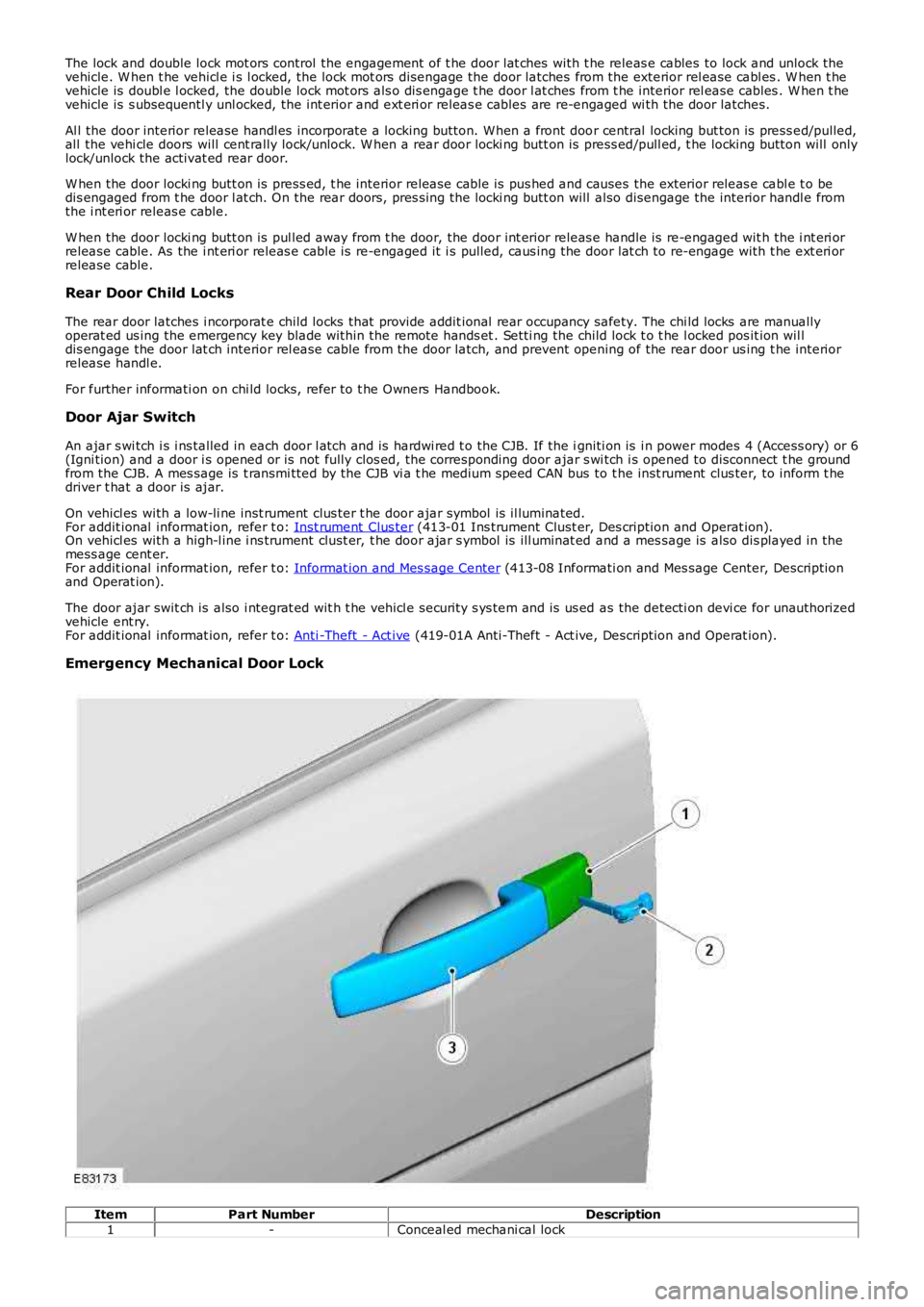
Emergency Mechanical Door Lock
ItemPart NumberDescription1-Conceal ed mechani cal lock
Page 2310 of 3229
2-Emergency key blade3-LH front door handl eThe remote hands et cont ai ns an emergency key blade, conceal ed in t he key fob. The front LH exterior door handleincorporates a mechanical operated door lock that i s conceal ed behind a removable plas ti c cover. The door lock all ows thefront LH door to be mechanicall y unlocked and locked us ing t he emergency key blade in the event that the remote cent rallocki ng operation fai ls, or a vehicl e power fai lure occurs.
W hen the mechanical door lock is us ed t he central l ocking syst em wil l not operat e, and if al ready armed the vehicle al armwi ll s ound when the door is opened. The vehicl e i s not abl e to be doubl e l ocked, or the al arm syst em armed usi ng theemergency key blade.
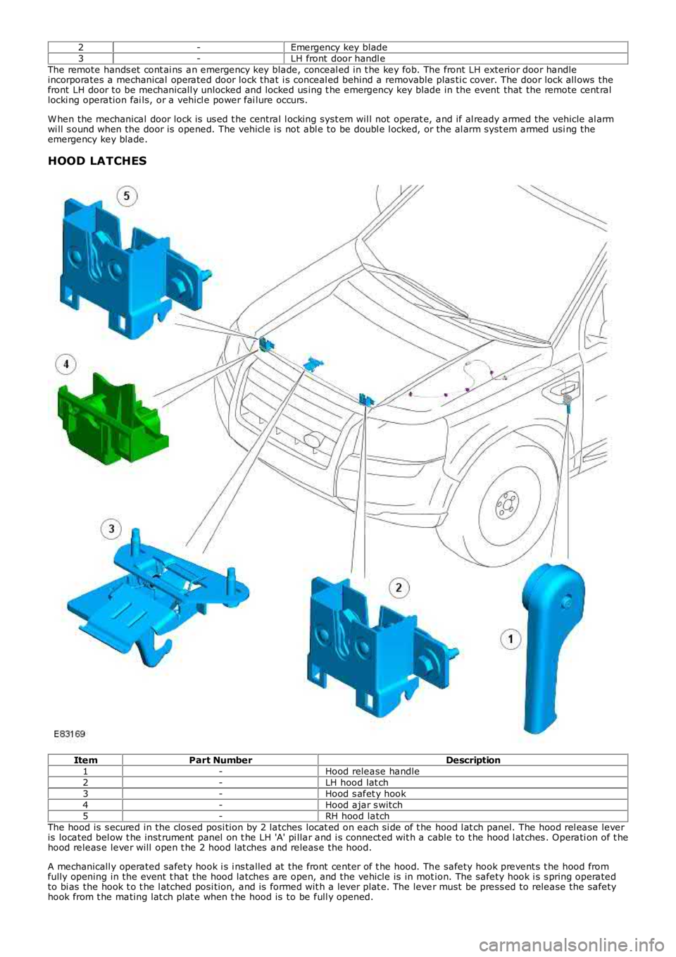
HOOD LATCHES
ItemPart NumberDescription1-Hood release handle2-LH hood lat ch3-Hood s afet y hook4-Hood ajar s witch5-RH hood latchThe hood is s ecured in the clos ed posi tion by 2 latches locat ed on each si de of t he hood l at ch panel. The hood rel ease leveris located bel ow t he inst rument panel on t he LH 'A' pi llar and i s connect ed wit h a cable to t he hood l at ches . Operati on of t hehood releas e lever will open t he 2 hood lat ches and releas e the hood.
A mechanicall y operated safety hook i s i ns talled at the front center of t he hood. The safety hook prevent s t he hood fromfully opening in the event t hat the hood latches are open, and the vehicle is in motion. The safety hook i s s pring operatedto bi as the hook t o t he l atched posi tion, and is formed wit h a lever plat e. The lever must be press ed to release the safetyhook from t he mating lat ch plat e when t he hood is to be full y opened.