2006 LAND ROVER FRELANDER 2 key
[x] Cancel search: keyPage 1971 of 3229
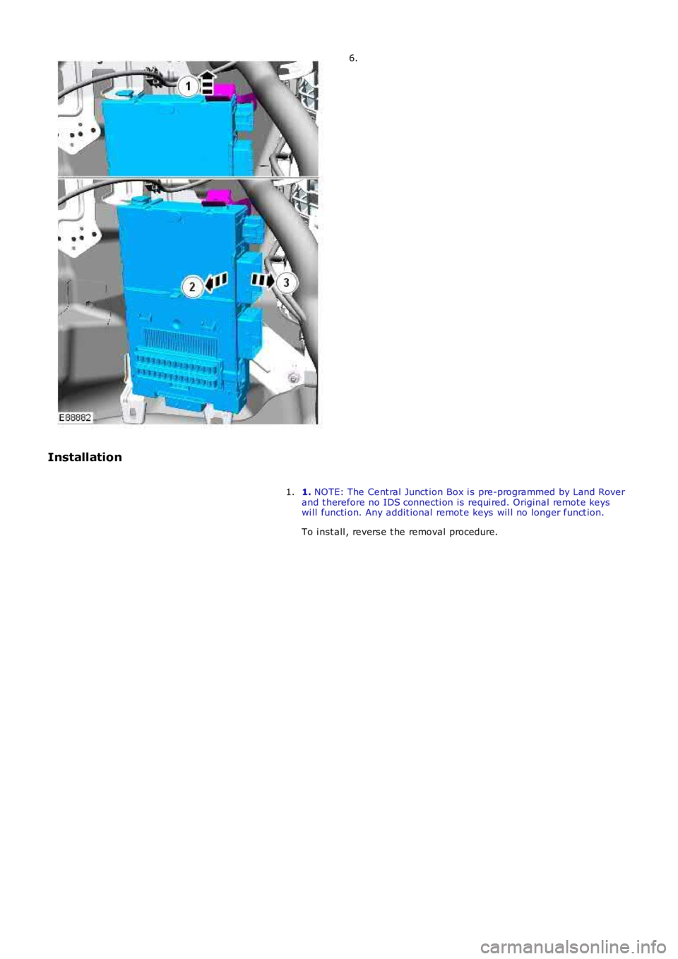
6.
Installation
1. NOTE: The Cent ral Junct ion Box i s pre-programmed by Land Roverand t herefore no IDS connecti on is requi red. Original remot e keyswi ll functi on. Any addit ional remot e keys wil l no longer funct ion.
To i nst all , revers e t he removal procedure.
1.
Page 2048 of 3229
The act ive ant i-theft sys tem monit ors the hi nged panels for unaut horized openi ng. In s ome markets the ant i-theft s ys temals o i ncorporates moni tori ng of the vehicl e int erior and vehicle ti lt s ens i ng.
The act ive ant i-theft al arm s ys t em i s cont rol led by t he fol lowi ng body sys tem cont rol modules :
CJBLeft Hand (LH) and Ri ght Hand (RH) front and rear door modul esIns t rument clus ter.
The CJB is the mai n cont rol ler in the sys tem. The CJB controls t he fol lowi ng securi ty funct ions , in addit ion to ot her vehicl efuncti ons :
Locking, doubl e l ocking and unlockingMonit oring of hi nged panel micros wi tches and panel ajar s t at esInt rus ion det ect ion modul eBatt ery backed sounder or vehicle hornsPass i ve armi ng and dis armi ngPani c alarm funct ionRemote hands et trans ponder readi ngInt eri or light ing.
Two l evels of vehicle ant i-t heft alarm are avai lable; peri meter mode moni tors all openi ng panel s and volumet ric mode (i ffi tt ed) monit ors t he vehi cle i nteri or for int rus ion and, in certai n market s, i t als o i ncorporates a ti lt s ens or t o monit or if t hevehi cl e i s being moved.
• NOTE: Volumet ri c mode and t ilt sens ing are not avai lable i n cert ain market s .
• NOTE: Volumet ri c mode is cancelled if t he vehi cl e is locked wit h any window or roof opening panel not clos ed t o avoi dinadvert ent al arm act ivati on.
The remot e handset provi des the followi ng functi onal it y:
Unlock (central unl ock or s i ngl e point entry)Lock and double lockLiftgate rel eas eApproach li ght ingPani c alarm.
The unlock and lock butt ons als o cont rol a 'lazy' l ock and unl ock feature which wi ll automat icall y cl ose or open t he wi ndowswit h an ext ended press of t he applicable but ton. This feature is onl y avai lable i n cert ain markets and i s cont rol led i nconjuct ion wit h the door modules .
W ARNING: Never doubl e l ock t he vehi cle wi th any pers on or ani mal ins ide.
• NOTE: Double l ocking is only avail abl e i n cert ai n market s .
The remot e handset contains an emergency access key. This can be us ed in the event of fail ure of t he remot e handset ort he vehi cl e batt ery t o unlock t he vehi cl e. The LH door handle contai ns a concealed mechanical key barrel which can beus ed wit h t he emergency key to acces s t he vehicle. This wi ll not dis able t he peri meter or int eri or al arm sys t ems which wi llbe acti vat ed when t he door i s opened. To cancel the al arm, t he remote hands et must be ins ert ed in t he s lot i n t he s tartcont rol module and the s t op/s tart but t on mus t be pres sed.
The remot e handset i s fi tt ed wi th an int egral vanadium lit hium rechargeabl e batt ery. The batt ery i s charged when it isins ert ed int o t he s lot in the st art control modul e.
CONTROL DIAGRAM
• NOTE: A = Hardwi red; F = RF Trans mis s ion; N = Medium Speed CAN bus; O = LIN bus ; W = LF Trans mi s si on
Page 2060 of 3229
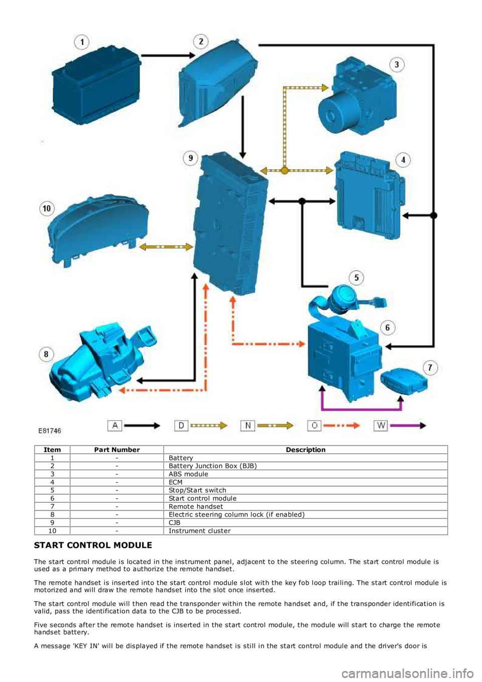
ItemPart NumberDescription
1-Bat t ery2-Bat t ery Junct ion Box (BJB)
3-ABS module
4-ECM5-St op/St art s wit ch
6-St art control modul e
7-Remot e handset8-El ect ri c s teering column l ock (i f enabled)
9-CJB
10-Ins trument cl ust er
START CONTROL MODULE
The s tart cont rol module i s located in t he ins t rument panel , adjacent t o t he s teeri ng col umn. The st art control modul e i sus ed as a pri mary method t o aut horize t he remot e handset .
The remot e handset i s ins ert ed int o t he s tart cont rol module s l ot wit h the key fob loop trai li ng. The s t art cont rol module ismot orized and wi ll draw the remot e hands et int o t he s lot once ins ert ed.
The s tart cont rol module wi ll t hen read t he t rans ponder wit hin t he remote hands et and, if t he t rans ponder identi fi cat ion i svalid, pas s the identi ficat ion data to the CJB t o be proces s ed.
Five s econds after t he remot e hands et is ins ert ed in the s t art cont rol module, t he module will s t art t o charge t he remot ehands et batt ery.
A mes s age 'KEY IN' wil l be dis played if t he remot e handset i s s ti ll i n the st art control modul e and t he dri ver's door is
Page 2061 of 3229
opened. The remot e handset i s removed from the st art control modul e by gentl y pushi ng the remote hands et int o t he st artcont rol module and releas ing. The s tart cont rol module mot or wil l then drive t he remot e hands et out from t he s lot as l ongas t he ignit ion i s off.
RF RECEIVER
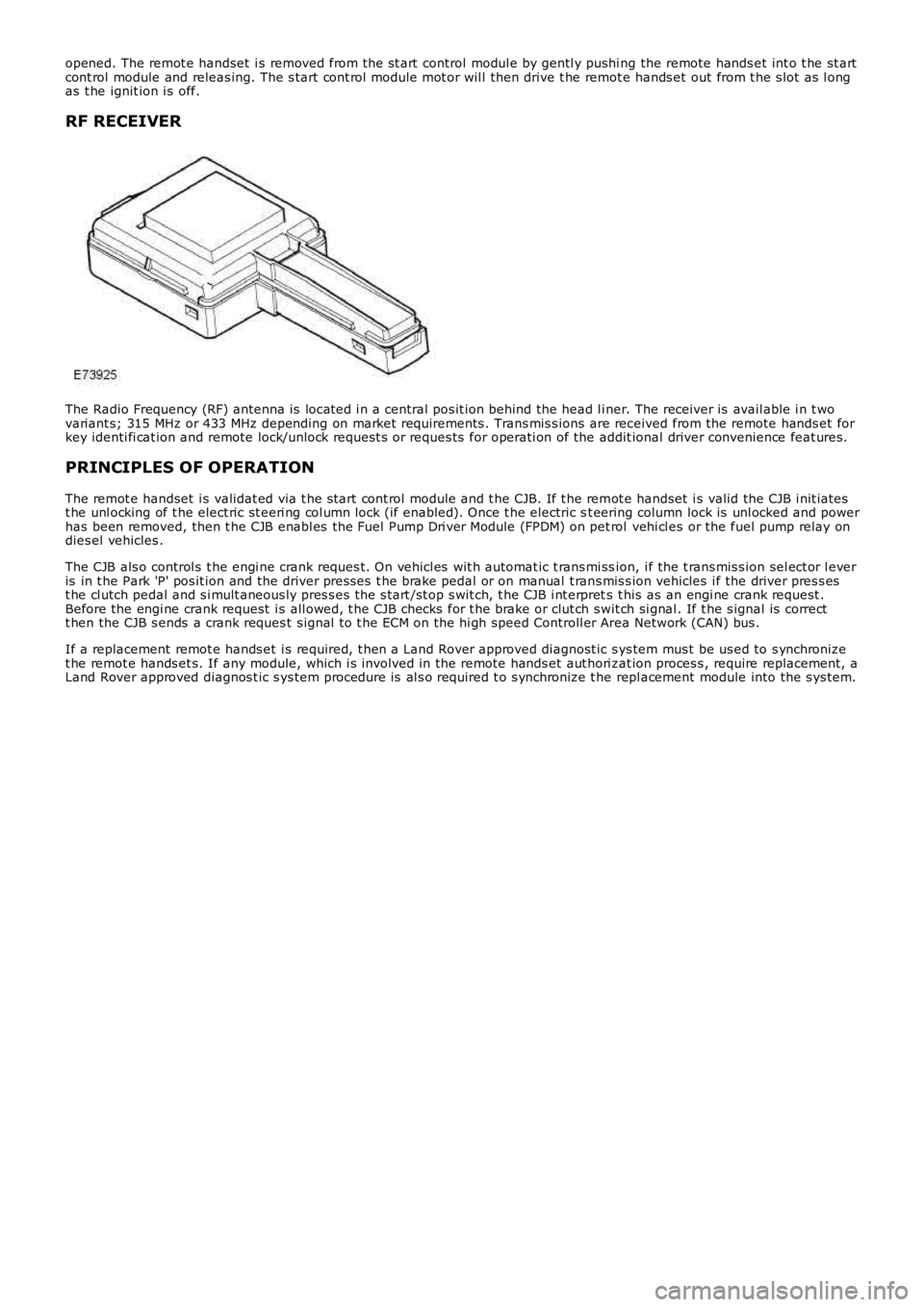
The Radio Frequency (RF) antenna is locat ed i n a central pos it ion behind the head l iner. The receiver is avail able i n t wovariant s; 315 MHz or 433 MHz depending on market requirements . Trans mis s ions are received from the remote hands et forkey identi fi cat ion and remote lock/unlock request s or reques ts for operati on of the addit ional driver convenience feat ures.
PRINCIPLES OF OPERATION
The remot e handset i s validat ed via t he s tart cont rol module and t he CJB. If t he remot e handset i s valid the CJB i nit iatest he unl ocking of t he elect ric st eeri ng col umn lock (if enabled). Once t he electric st eering column lock is unl ocked and powerhas been removed, then t he CJB enabl es the Fuel Pump Dri ver Module (FPDM) on pet rol vehi cl es or the fuel pump relay ondies el vehicles .
The CJB als o control s t he engi ne crank reques t. On vehicl es wit h automat ic t rans mi ssion, i f the t rans mis s ion sel ect or l everis in t he Park 'P' pos it ion and the driver pres ses t he brake pedal or on manual t rans mis s ion vehicles i f the driver pres s est he cl utch pedal and s i mult aneous ly pres s es t he s tart /st op s wit ch, t he CJB i nt erprets t his as an engi ne crank request .Before the engi ne crank request i s all owed, t he CJB checks for t he brake or clut ch swit ch si gnal . If t he s ignal is correctt hen the CJB s ends a crank reques t s ignal t o t he ECM on the hi gh speed Controll er Area Network (CAN) bus .
If a replacement remot e hands et i s required, t hen a Land Rover approved diagnost ic sys tem mus t be us ed to s ynchronizet he remot e hands et s. If any module, which i s involved in the remote hands et aut hori zat ion proces s , require replacement, aLand Rover approved diagnos t ic s ys tem procedure is al s o required t o s ynchronize t he repl acement module into the s ys tem.
Page 2062 of 3229
Publi s hed: 11-May-2011
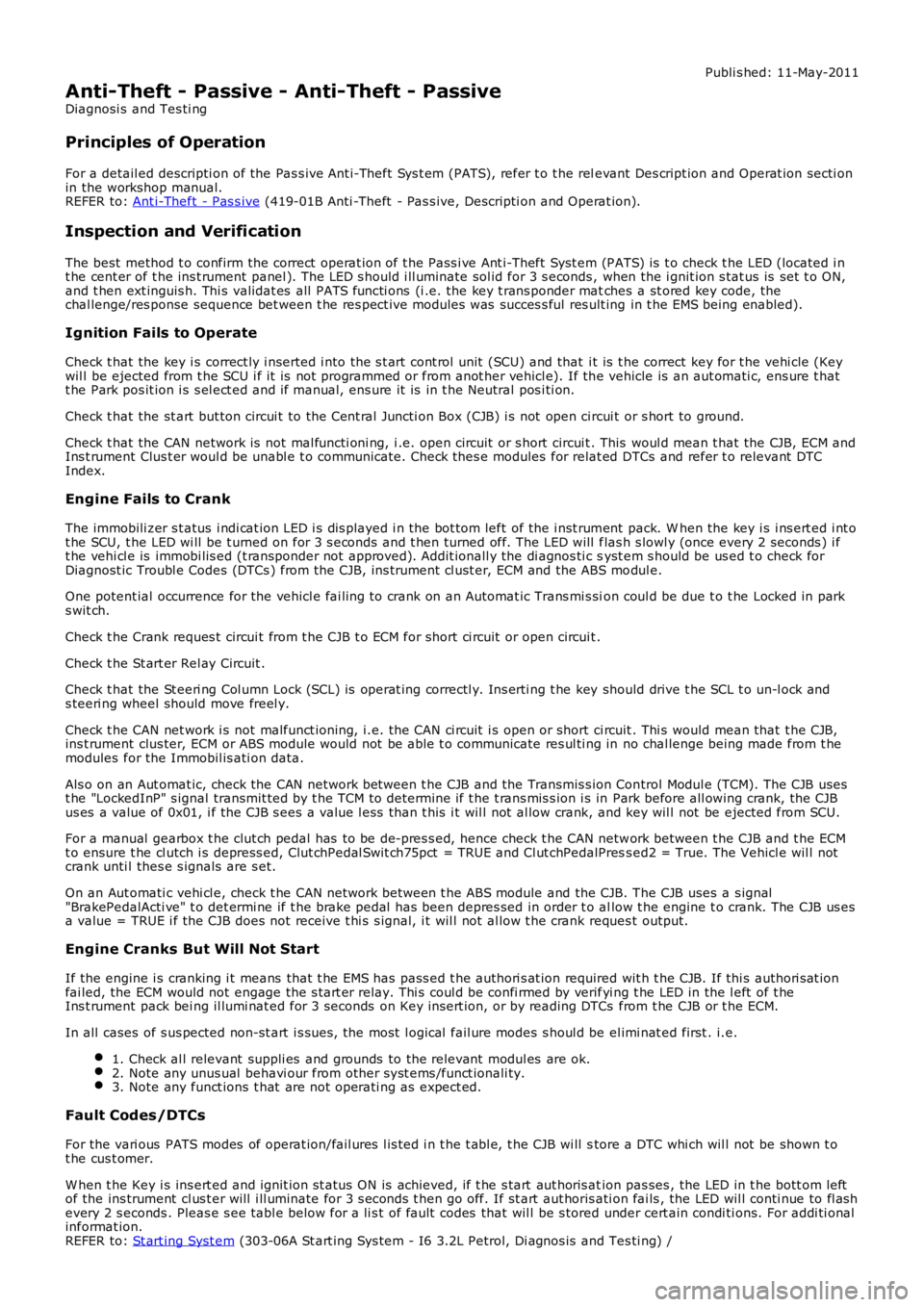
Anti-Theft - Passive - Anti-Theft - Passive
Diagnosi s and Tes ti ng
Principles of Operation
For a detail ed descripti on of the Pas s ive Ant i-Theft Sys t em (PATS), refer t o t he relevant Des cript ion and Operat ion secti onin the workshop manual.REFER to: Ant i-Theft - Pas s ive (419-01B Anti -Theft - Pas s ive, Descripti on and Operat ion).
Inspection and Verification
The best method t o confirm the correct operat ion of t he Pass i ve Ant i-Theft Syst em (PATS) is t o check t he LED (located i nt he cent er of t he ins t rument panel ). The LED s hould i ll uminate sol id for 3 s econds , when the i gnit ion s tat us is set t o ON,and t hen ext inguis h. Thi s validat es all PATS functi ons (i .e. the key t rans ponder matches a st ored key code, thechal lenge/res ponse sequence bet ween t he res pect ive modules was succes s ful res ult ing in t he EMS being enabled).
Ignition Fails to Operate
Check t hat the key i s correct ly i nserted i nto the s t art cont rol unit (SCU) and that i t is t he correct key for t he vehi cle (Keywil l be ejected from t he SCU i f it is not programmed or from anot her vehicl e). If the vehicle is an aut omati c, ens ure t hatt he Park pos it ion i s s el ect ed and if manual, ens ure it is in t he Neutral pos i ti on.
Check t hat the st art but ton circui t to the Cent ral Juncti on Box (CJB) i s not open circui t or s hort to ground.
Check t hat the CAN network is not mal functi oni ng, i .e. open circuit or s hort circui t. This woul d mean t hat the CJB, ECM andIns t rument Clus t er woul d be unabl e t o communicate. Check thes e modules for relat ed DTCs and refer t o relevant DTCIndex.
Engine Fails to Crank
The immobili zer s t atus i ndi cat ion LED i s dis played i n the bot tom left of the i nst rument pack. W hen the key i s i ns ert ed i nt ot he SCU, t he LED wi ll be t urned on for 3 s econds and t hen turned off. The LED will flas h s lowl y (once every 2 seconds ) i ft he vehi cl e is immobi lis ed (t ransponder not approved). Addit ionall y the di agnos ti c syst em s hould be us ed t o check forDiagnost ic Troubl e Codes (DTCs ) from the CJB, ins trument cl ust er, ECM and the ABS modul e.
One potent ial occurrence for the vehicl e fai ling to crank on an Automat ic Trans mi s sion coul d be due t o t he Locked in parks wit ch.
Check t he Crank reques t circui t from t he CJB t o ECM for short ci rcuit or open circuit .
Check t he St art er Rel ay Circuit .
Check t hat the St eeri ng Col umn Lock (SCL) is operat ing correctl y. Ins erti ng t he key should drive t he SCL t o un-l ock ands teeri ng wheel should move freel y.
Check t he CAN net work i s not malfunct ioning, i.e. the CAN ci rcuit i s open or short ci rcuit . Thi s would mean that t he CJB,ins t rument clus ter, ECM or ABS module would not be abl e t o communicate res ul ti ng in no chal lenge being made from t hemodules for the Immobil is ati on data.
Als o on an Aut omat ic, check the CAN network between t he CJB and the Transmis s ion Control Modul e (TCM). The CJB usest he "LockedInP" s ignal transmit ted by t he TCM to det ermi ne if t he t rans mis s ion i s in Park before all owing crank, the CJBus es a value of 0x01, i f the CJB s ees a value l ess than t his i t wil l not al low crank, and key wil l not be ejected from SCU.
For a manual gearbox t he clut ch pedal has to be de-pres s ed, hence check t he CAN network between t he CJB and t he ECMt o ensure t he cl utch i s depress ed, Clut chPedal Swit ch75pct = TRUE and Cl ut chPedalPress ed2 = True. The Vehicl e wil l notcrank unti l thes e s ignals are s et.
On an Aut omati c vehi cl e, check t he CAN network between t he ABS module and the CJB. The CJB uses a s ignal"BrakePedalActi ve" t o det ermi ne if t he brake pedal has been depres sed in order t o allow t he engine t o crank. The CJB us esa value = TRUE i f the CJB does not receive t hi s s ignal, i t wil l not al low t he crank reques t output.
Engine Cranks But Will Not Start
If the engine i s cranking i t means that t he EMS has pass ed t he authori s at ion required wit h t he CJB. If thi s authori s at ionfai led, the ECM would not engage the s t art er relay. Thi s coul d be confi rmed by verifyi ng t he LED in the l eft of t heIns t rument pack bei ng il lumi nat ed for 3 seconds on Key ins ert ion, or by reading DTCs from t he CJB or t he ECM.
In all cases of s us pected non-st art i s sues , the most l ogical fail ure modes s houl d be el imi nat ed first . i.e.
1. Check al l relevant suppli es and grounds to the relevant modul es are ok.2. Note any unus ual behavi our from other s yst ems /funct ionali ty.3. Note any funct ions t hat are not operati ng as expect ed.
Fault Codes/DTCs
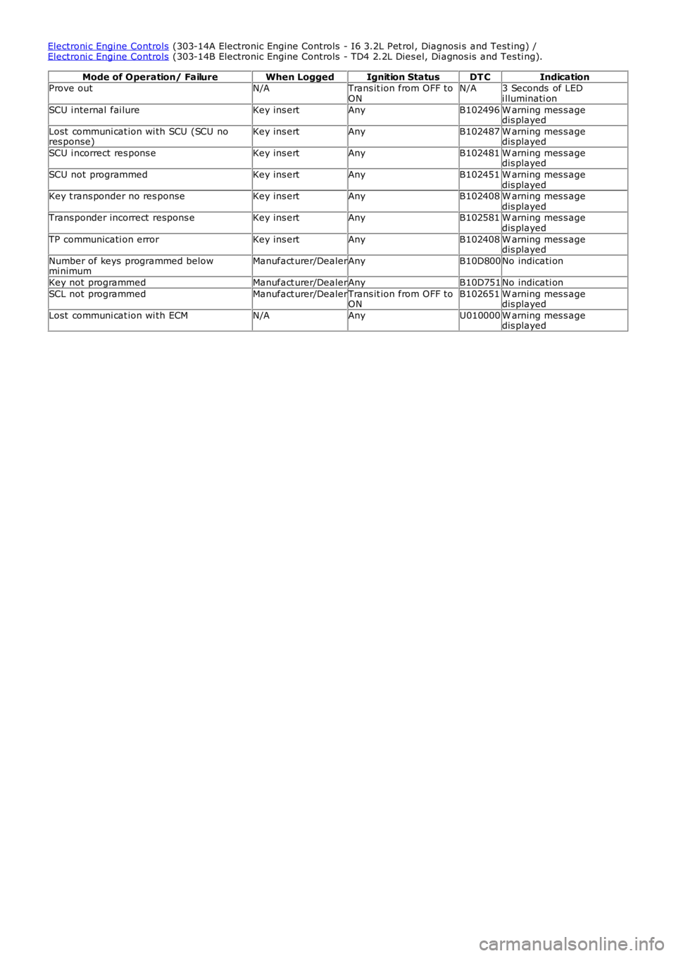
For the vari ous PATS modes of operat ion/fail ures l is ted i n t he t abl e, t he CJB wi ll store a DTC whi ch wil l not be shown t ot he cus t omer.
W hen t he Key i s ins ert ed and ignit ion st atus ON is achieved, if t he s tart aut horis ation pas ses , the LED in t he bott om leftof the ins trument cl us t er will i ll uminate for 3 s econds t hen go off. If st art aut horis ati on fai ls , the LED wil l conti nue to fl as hevery 2 s econds . Pleas e s ee tabl e below for a li s t of fault codes that wil l be s tored under cert ain condi ti ons. For addi ti onalinformat ion.REFER to: St art ing Syst em (303-06A St art ing Sys tem - I6 3.2L Petrol, Di agnos is and Tes ti ng) /
Page 2063 of 3229
Electroni c Engine Controls (303-14A Electronic Engine Controls - I6 3.2L Pet rol , Diagnosi s and Test ing) /Electroni c Engine Controls (303-14B Electronic Engine Controls - TD4 2.2L Dies el, Di agnos is and Tes ti ng).
Mode of Operation/ FailureWhen LoggedIgnition StatusDT CIndicationProve outN/ATrans it ion from OFF toONN/A3 Seconds of LEDi lluminati on
SCU i nternal fai lureKey ins ertAnyB102496W arning mes s agedis played
Lost communi cat ion wi th SCU (SCU nores ponse)Key ins ertAnyB102487W arning mes s agedis played
SCU i ncorrect res pons eKey ins ertAnyB102481W arning mes s agedis played
SCU not programmedKey ins ertAnyB102451W arning mes s agedis playedKey t rans ponder no res ponseKey ins ertAnyB102408W arning mes s agedis playedTrans ponder incorrect respons eKey ins ertAnyB102581W arning mes s agedis played
TP communicati on errorKey ins ertAnyB102408W arning mes s agedis played
Number of keys programmed belowmi nimumManufact urer/DealerAnyB10D800No indicati on
Key not programmedManufact urer/DealerAnyB10D751No indicati on
SCL not programmedManufact urer/DealerTrans it ion from OFF toONB102651W arning mes s agedis played
Lost communi cat ion wi th ECMN/AAnyU010000W arning mes s agedis played
Page 2073 of 3229
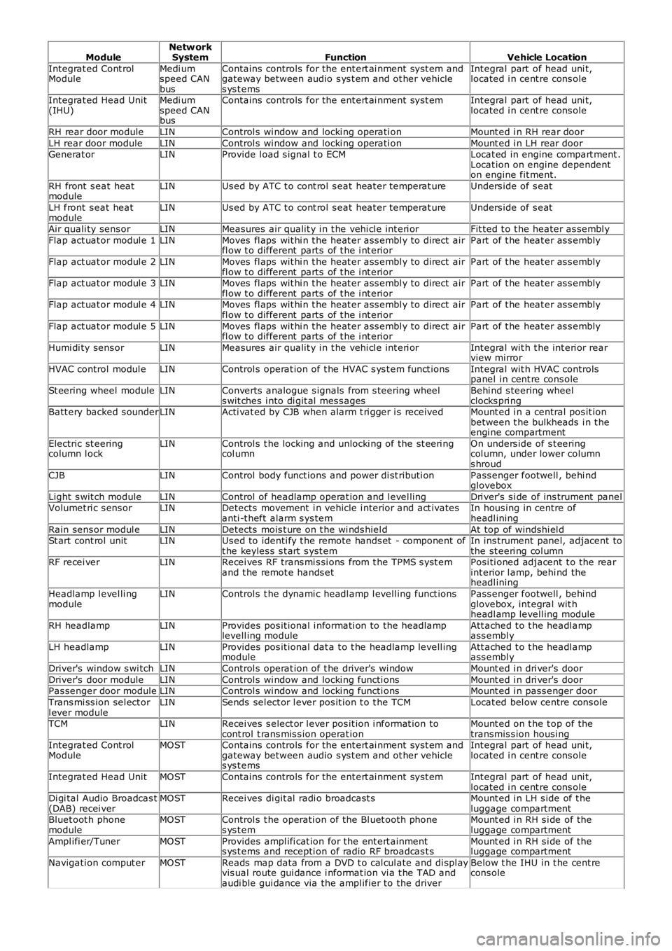
ModuleNetw orkSystemFunctionVehicle Location
Integrat ed Cont rolModuleMedi umspeed CANbus
Contains controls for the ent ert ai nment sys t em andgateway between audio s ys t em and ot her vehicles ys t ems
Int egral part of head uni t,located i n cent re cons ole
Integrat ed Head Unit(IHU)Medi umspeed CANbus
Contains controls for the ent ert ai nment sys t emInt egral part of head uni t,located i n cent re cons ole
RH rear door moduleLINControl s wi ndow and locki ng operati onMount ed i n RH rear door
LH rear door moduleLINControl s wi ndow and locki ng operati onMount ed i n LH rear doorGenerat orLINProvide l oad s ignal t o ECMLocat ed in engine compart ment .Locat ion on engine dependenton engine fit ment.
RH front s eat heatmoduleLINUs ed by ATC t o cont rol s eat heat er temperat ureUnders ide of s eat
LH front s eat heatmoduleLINUs ed by ATC t o cont rol s eat heat er temperat ureUnders ide of s eat
Air quali ty sens orLINMeasures air qualit y i n t he vehi cl e int eri orFit ted t o t he heater as sembl y
Flap act uat or modul e 1LINMoves fl aps wit hi n t he heat er ass embl y to direct airfl ow t o different parts of t he i nt eri orPart of t he heat er as s embly
Flap act uat or modul e 2LINMoves fl aps wit hi n t he heat er ass embl y to direct airfl ow t o different parts of t he i nt eri orPart of t he heat er as s embly
Flap act uat or modul e 3LINMoves fl aps wit hi n t he heat er ass embl y to direct airfl ow t o different parts of t he i nt eri orPart of t he heat er as s embly
Flap act uat or modul e 4LINMoves fl aps wit hi n t he heat er ass embl y to direct airfl ow t o different parts of t he i nt eri orPart of t he heat er as s embly
Flap act uat or modul e 5LINMoves fl aps wit hi n t he heat er ass embl y to direct airfl ow t o different parts of t he i nt eri orPart of t he heat er as s embly
Humi di ty sens orLINMeasures air qualit y i n t he vehi cl e int eri orInt egral wit h t he int eri or rearview mirror
HVAC control modul eLINControl s operat ion of t he HVAC s ys t em funct ionsInt egral wit h HVAC controlspanel i n cent re cons ole
St eering wheel moduleLINConverts analogue s ignals from s teering wheels wit ches i nto di git al mes s agesBehi nd s teering wheelclocks pri ngBatt ery backed s ounderLINActi vat ed by CJB when alarm t ri gger i s receivedMount ed i n a central pos it ionbetween t he bulkheads i n t heengi ne compartment
Electric st eeringcolumn l ockLINControl s t he locking and unlocki ng of the st eeri ngcol umnOn unders ide of s t eeringcol umn, under lower columns hroud
CJBLINControl body funct ions and power di st ributi onPass enger footwell , behi ndglovebox
Light s wit ch moduleLINControl of headlamp operat ion and l evel lingDri ver's s i de of ins trument panelVolumet ri c s ens orLINDetects movement i n vehicle i nterior and act ivatesanti -t heft alarm s ys temIn hous ing in centre ofheadl ining
Rain sens or modul eLINDetects mois t ure on t he wi nds hiel dAt top of windshi el dSt art cont rol unitLINUs ed to identi fy t he remote hands et - component oft he keyles s s t art s yst emIn ins trument panel, adjacent tothe st eeri ng col umnRF recei verLINRecei ves RF trans mi s si ons from t he TPMS s yst emand t he remot e hands etPosi ti oned adjacent t o the rearint erior l amp, behi nd theheadl ining
Headlamp l evel li ngmoduleLINControl s t he dynami c headl amp l evell ing funct ionsPass enger footwell , behi ndglovebox, int egral wit hheadl amp levell ing module
RH headlampLINProvides pos it ional i nformati on to the headlamplevell ing moduleAtt ached t o t he headl ampass embl y
LH headlampLINProvides pos it ional dat a t o t he headlamp levell ingmoduleAtt ached t o t he headl ampass embl y
Driver's window s wi tchLINControl s operat ion of t he driver's wi ndowMount ed i n dri ver's door
Driver's door moduleLINControl s wi ndow and locki ng functi onsMount ed i n dri ver's doorPas senger door moduleLINControl s wi ndow and locki ng functi onsMount ed i n pass enger door
Trans mi ss ion sel ect orl ever moduleLINSends sel ect or l ever pos it ion t o t he TCMLocat ed bel ow centre cons ole
TCMLINRecei ves s elect or l ever pos it ion i nformat ion tocont rol t rans mis s ion operat ionMount ed on t he t op of thetransmis s ion housi ngIntegrat ed Cont rolModuleMOSTContains controls for the ent ert ai nment sys t em andgateway between audio s ys t em and ot her vehicles ys t ems
Int egral part of head uni t,located i n cent re cons ole
Integrat ed Head UnitMOSTContains controls for the ent ert ai nment sys t emInt egral part of head uni t,located i n cent re cons oleDi gi tal Audio Broadcas t(DAB) recei verMOSTRecei ves di git al radi o broadcast sMount ed i n LH s ide of t heluggage compartmentBluet oot h phonemoduleMOSTControl s t he operati on of the Bl uet ooth phones ys t emMount ed i n RH s i de of theluggage compartment
Ampl ifi er/TunerMOSTProvides ampl ifi cat ion for the ent ert ainments ys t ems and recepti on of radio RF broadcas t sMount ed i n RH s i de of theluggage compartment
Navigati on comput erMOSTReads map data from a DVD t o cal cul ate and di spl ayvis ual route gui dance i nformat ion vi a t he TAD andaudi ble gui dance via the ampl ifier to the driver
Below t he IHU i n t he cent recons ole
Page 2078 of 3229
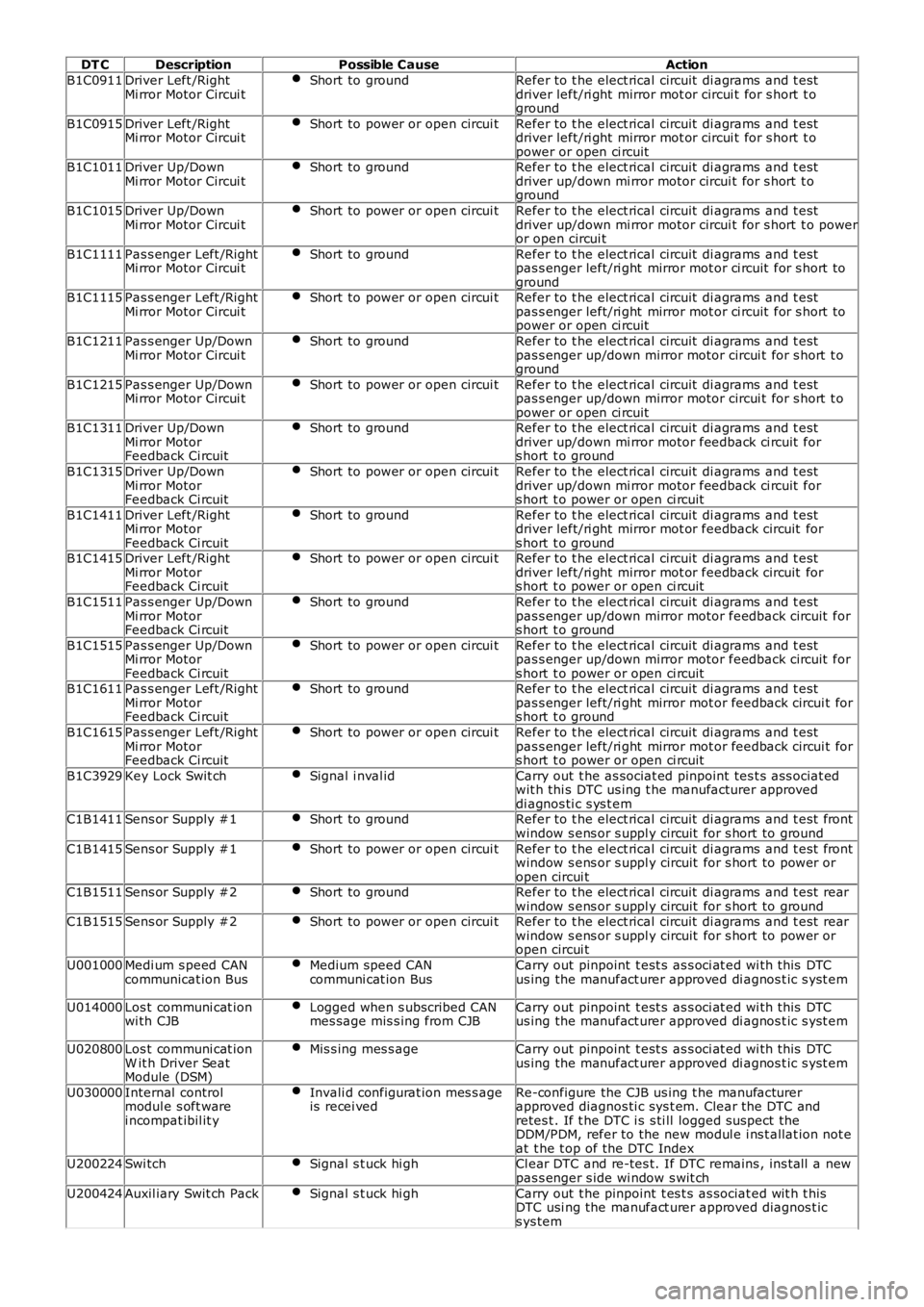
DT C
Description Possible Cause Action
B1C0911 Driver Left /Right
Mi rror Motor Circui t Short to ground Refer to t he elect rical circuit di agrams and t est
driver left/ri ght mirror mot or circui t for s hort t o
ground
B1C0915 Driver Left /Right
Mi rror Motor Circui t Short to power or open circui t Refer to t he elect rical circuit di agrams and t est
driver left/ri ght mirror mot or circui t for s hort t o
power or open ci rcuit
B1C1011 Driver Up/Down
Mi rror Motor Circui t Short to ground Refer to t he elect rical circuit di agrams and t est
driver up/down mi rror motor circui t for s hort t o
ground
B1C1015 Driver Up/Down
Mi rror Motor Circui t Short to power or open circui t Refer to t he elect rical circuit di agrams and t est
driver up/down mi rror motor circui t for s hort t o power
or open circui t
B1C1111 Pas s enger Left /Right
Mi rror Motor Circui t Short to ground Refer to t he elect rical circuit di agrams and t est
pas s enger left/ri ght mirror mot or ci rcuit for s hort t o
ground
B1C1115 Pas s enger Left /Right
Mi rror Motor Circui t Short to power or open circui t Refer to t he elect rical circuit di agrams and t est
pas s enger left/ri ght mirror mot or ci rcuit for s hort t o
power or open ci rcuit
B1C1211 Pas s enger Up/Down
Mi rror Motor Circui t Short to ground Refer to t he elect rical circuit di agrams and t est
pas s enger up/down mirror motor circui t for s hort t o
ground
B1C1215 Pas s enger Up/Down
Mi rror Motor Circui t Short to power or open circui t Refer to t he elect rical circuit di agrams and t est
pas s enger up/down mirror motor circui t for s hort t o
power or open ci rcuit
B1C1311 Driver Up/Down
Mi rror Motor
Feedback Ci rcuit Short to ground Refer to t he elect rical circuit di agrams and t est
driver up/down mi rror motor feedback ci rcuit for
s hort t o ground
B1C1315 Driver Up/Down
Mi rror Motor
Feedback Ci rcuit Short to power or open circui t Refer to t he elect rical circuit di agrams and t est
driver up/down mi rror motor feedback ci rcuit for
s hort t o power or open ci rcuit
B1C1411 Driver Left /Right
Mi rror Motor
Feedback Ci rcuit Short to ground Refer to t he elect rical circuit di agrams and t est
driver left/ri ght mirror mot or feedback circuit for
s hort t o ground
B1C1415 Driver Left /Right
Mi rror Motor
Feedback Ci rcuit Short to power or open circui t Refer to t he elect rical circuit di agrams and t est
driver left/ri ght mirror mot or feedback circuit for
s hort t o power or open ci rcuit
B1C1511 Pas s enger Up/Down
Mi rror Motor
Feedback Ci rcuit Short to ground Refer to t he elect rical circuit di agrams and t est
pas s enger up/down mirror motor feedback circuit for
s hort t o ground
B1C1515 Pas s enger Up/Down
Mi rror Motor
Feedback Ci rcuit Short to power or open circui t Refer to t he elect rical circuit di agrams and t est
pas s enger up/down mirror motor feedback circuit for
s hort t o power or open ci rcuit
B1C1611 Pas s enger Left /Right
Mi rror Motor
Feedback Ci rcuit Short to ground Refer to t he elect rical circuit di agrams and t est
pas s enger left/ri ght mirror mot or feedback circui t for
s hort t o ground
B1C1615 Pas s enger Left /Right
Mi rror Motor
Feedback Ci rcuit Short to power or open circui t Refer to t he elect rical circuit di agrams and t est
pas s enger left/ri ght mirror mot or feedback circui t for
s hort t o power or open ci rcuit
B1C3929 Key Lock Swit ch Signal i nval id Carry out t he as sociat ed pinpoint tes t s ass ociat ed
wit h thi s DTC us ing t he manufacturer approved
di agnos ti c s ys t em
C1B1411 Sens or Supply #1 Short to ground Refer to t he elect rical circuit di agrams and t est front
window s ens or s uppl y circuit for s hort to ground
C1B1415 Sens or Supply #1 Short to power or open circui t Refer to t he elect rical circuit di agrams and t est front
window s ens or s uppl y circuit for s hort to power or
open circui t
C1B1511 Sens or Supply #2 Short to ground Refer to t he elect rical circuit di agrams and t est rear
window s ens or s uppl y circuit for s hort to ground
C1B1515 Sens or Supply #2 Short to power or open circui t Refer to t he elect rical circuit di agrams and t est rear
window s ens or s uppl y circuit for s hort to power or
open circui t
U001000 Medi um s peed CAN
communicat ion Bus Medium speed CAN
communi cat ion Bus Carry out pinpoint t est s as s oci at ed wi th this DTC
us ing the manufact urer approved di agnos t ic s yst em
U014000 Los t communi cat ion
wi th CJB Logged when s ubscribed CAN
mes sage mis s ing from CJB Carry out pinpoint t est s as s oci at ed wi th this DTC
us ing the manufact urer approved di agnos t ic s yst em
U020800 Los t communi cat ion
W it h Driver Seat
Module (DSM) Mis s ing mes s age Carry out pinpoint t est s as s oci at ed wi th this DTC
us ing the manufact urer approved di agnos t ic s yst em
U030000 Internal control
modul e s oft ware
i ncompat ibil it y Invali d configurat ion mes s age
is recei ved Re-configure the CJB us ing t he manufacturer
approved diagnos ti c sys t em. Clear the DTC and
retes t . If t he DTC i s s ti ll logged s uspect the
DDM/PDM, refer to the new modul e i ns t allat ion not e
at t he t op of the DTC Index
U200224 Swi tch Signal s t uck hi gh Cl ear DTC and re-tes t. If DTC remains , ins tall a new
pas s enger s ide wi ndow s wit ch
U200424 Auxil iary Swit ch Pack Signal s t uck hi gh Carry out t he pinpoint t es t s as sociat ed wit h t his
DTC usi ng the manufact urer approved diagnos t ic
s ys tem