Page 1980 of 5267

RETAINER - CRANK REAR OIL SEAL
REMOVAL
1. Disconnect the battery negative cables.
2. Raise vehicle on hoist.
3. Remove the oil pan drain plug and drain the engine
oil. Re-install plug and torque to 50 Nꞏm (44 ft. lbs.)
torque.
4. Remove transmission and transfer case (if
equipped) from vehicle.
5. Remove flywheel or torque converter drive plate.
6. Remove flywheel adapter plate.
7. Disconnect starter cables from starter motor.
8. Remove starter motor (Refer to 8 - ELECTRICAL/
STARTING/STARTER MOTOR - REMOVAL) and
transmission adapter plate assembly.
9. Remove four 4 oil pan rear bolts. Slide a feeler
gauge between the seal retainer and oil pan gasket
to break the seal.
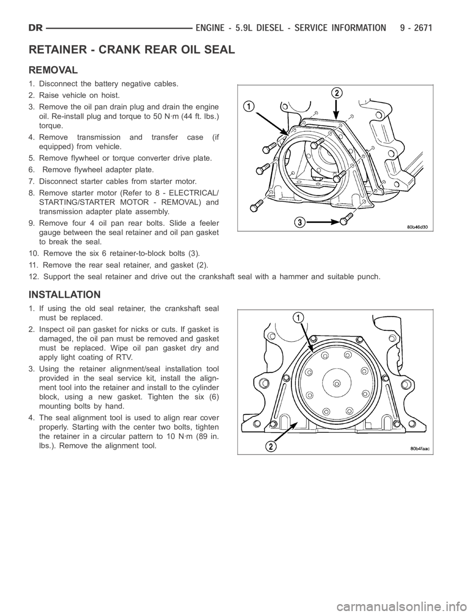
10. Remove the six 6 retainer-to-block bolts (3).
11. Remove the rear seal retainer, and gasket (2).
12. Support the seal retainer and drive out the crankshaft seal with a hammer and suitable punch.
INSTALLATION
1. If using the old seal retainer, the crankshaft seal
must be replaced.
2. Inspect oil pan gasket for nicks or cuts. If gasket is
damaged, the oil pan must be removed and gasket
must be replaced. Wipe oil pan gasket dry and
apply light coating of RTV.
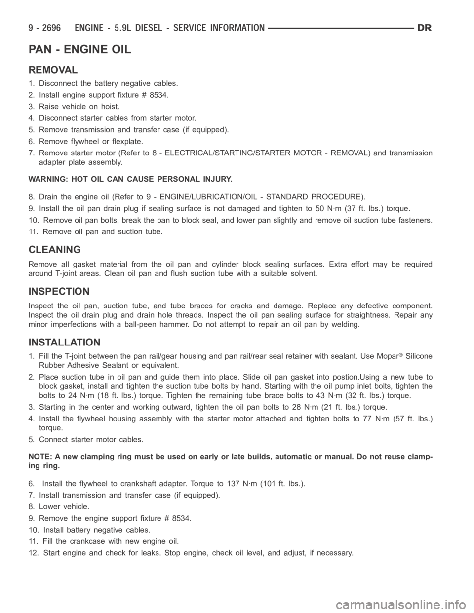
3. Using the retainer alignment/seal installation tool
provided in the seal service kit, install the align-
ment tool into the retainer and install to the cylinder
block, using a new gasket. Tighten the six (6)
mounting bolts by hand.
4. The seal alignment tool is used to align rear cover
properly. Starting with the center two bolts, tighten
the retainer in a circular pattern to 10 Nꞏm (89 in.
lbs.). Remove the alignment tool.
Page 1994 of 5267
MOUNT - FRONT
REMOVAL
1. Disconnect the battery negative cables.
2. Remove the viscous fan/drive assembly (Refer to 7
- COOLING/ENGINE/RADIATOR FAN -
REMOVAL).
3. Raise vehicle on hoist.
4. Install engine support fixture tool# 8534 and steel
bracket tool # 8534A
5. Loosen the thru-bolt and nut.
6. Lift the engine SLIGHTLY and remove the insulator
to block bolts.
7. Remove the RH insulator (2) from the vehicle.
8. Remove the LH insulator (2) from the vehicle.
Page 1995 of 5267
INSTALLATION
1. With engine raised SLIGHTLY, position the LH
insulator (2) to the mount. Install the bolts and
torque to specification.
2. With engine raised SLIGHTLY, position the RH
insulator (2) to the mount. Install the bolts and
torque to specification.
3. Lower the engine using tool # 8534, while guiding
the mount and thru-bolt into the frame mounted
support cushion brackets.
4. Install the thru bolt nut and tighten the nut to 95
Nꞏm (70 ft. lbs.) torque.
5. Remove the engine support fixture tool # 8534.
6. Lower the vehicle.
7. Install the viscous fan/drive assembly (Refer to 7 -
COOLING/ENGINE/RADIATOR FAN - INSTALLA-
TION).
8. Connect the battery negative cables.
Page 1996 of 5267
MOUNT - REAR
REMOVAL
1. Raise the vehicle on a hoist.
2. Position a transmission jack in place.
3. Remove support cushion stud nuts.
4. Raise rear of transmission and engine SLIGHTLY.
5. Remove the bolts holding the support cushion to the transmission support bracket. Remove the support cushion.
6. If necessary, remove the bolts holding the transmission support bracket to the transmission.
INSTALLATION
1. If removed, position the transmission support bracket to the transmission. Install new attaching bolts and tighten
to 102 Nꞏm (75 ft. lbs.) torque.
2. Position support cushion to transmission support bracket. Install stud nuts and tighten to 47 Nꞏm (35 ft. lbs.)
torque.
3. Using the transmission jack, lower the transmission and support cushion onto the crossmember .
4. Install the support cushion bolts and tighten to 47 Nꞏm (35 ft. lbs.) torque.
5. Remove the transmission jack.
6. Lower the vehicle.
Page 2004 of 5267
FILTER - ENGINE OIL
REMOVAL
1. Clean the area around the oil filter head. Remove the filter from below using a cap-style filter wrench.
2. Clean the gasket surface of the filter head. The filter canister O-Ring seal can stick on the filter head. Make sure
it is removed.
INSTALLATION
1. Fill the oil filter element with clean oil before installation. Use the same type oil that will be used in the engine.
2. Apply a light film of lubricating oil to the sealing surface before installing the filter.
CAUTION: Mechanical over-tightening may distort the threads or damage the filter element seal.
3. Install the filter until it contacts the sealing surface of the oil filter adapter. Tighten filter an additional
1⁄2turn.
Page 2005 of 5267

PA N - E N G I N E O I L
REMOVAL
1. Disconnect the battery negative cables.
2. Install engine support fixture # 8534.
3. Raise vehicle on hoist.
4. Disconnect starter cables from starter motor.
5. Remove transmission and transfer case (if equipped).
6. Remove flywheel or flexplate.
7. Remove starter motor (Refer to 8 - ELECTRICAL/STARTING/STARTER MOTOR -REMOVAL) and transmission
adapter plate assembly.
WARNING: HOT OIL CAN CAUSE PERSONAL INJURY.
8. Drain the engine oil (Refer to 9 - ENGINE/LUBRICATION/OIL - STANDARD PROCEDURE).
9. Install the oil pan drain plug if sealing surface is not damaged and tighten to 50 Nꞏm (37 ft. lbs.) torque.
10. Remove oil pan bolts, break the pan to block seal, and lower pan slightlyandremoveoilsuctiontubefasteners.
11. Remove oil pan and suction tube.
CLEANING
Remove all gasket material from the oil pan and cylinder block sealing surfaces. Extra effort may be required
around T-joint areas. Clean oil pan and flush suction tube with a suitable solvent.
INSPECTION
Inspect the oil pan, suction tube, and tube braces for cracks and damage. Replace any defective component.
Inspect the oil drain plug and drain hole threads. Inspect the oil pan sealing surface for straightness. Repair any
minor imperfections with a ball-peen hammer. Do not attempt to repair an oil pan by welding.
INSTALLATION
1. Fill the T-joint between the pan rail/gear housing and pan rail/rear seal retainer with sealant. Use MoparSilicone
Rubber Adhesive Sealant or equivalent.
2. Place suction tube in oil pan and guide them into place. Slide oil pan gasket into postion.Using a new tube to
block gasket, install and tighten the suction tube bolts by hand. Startingwith the oil pump inlet bolts, tighten the
bolts to 24 Nꞏm (18 ft. lbs.) torque. Tighten the remaining tube brace boltsto 43 Nꞏm (32 ft. lbs.) torque.
3. Starting in the center and working outward, tighten the oil pan bolts to 28Nꞏm(21ft.lbs.)torque.
4. Install the flywheel housing assembly with the starter motor attached and tighten bolts to 77 Nꞏm (57 ft. lbs.)
torque.
5. Connect starter motor cables.
NOTE: A new clamping ring must be used on early or late builds, automatic or manual. Do not reuse clamp-
ing ring.
6. Install the flywheel to crankshaft adapter. Torque to 137 Nꞏm (101 ft. lbs.).
7. Install transmission and transfer case (if equipped).
8. Lower vehicle.
9. Remove the engine support fixture # 8534.
10. Install battery negative cables.
11. Fill the crankcase with new engine oil.
12. Start engine and check for leaks. Stop engine, check oil level, and adjust, if necessary.
Page 2022 of 5267
ENGINE - 8.3L - SERVICE INFORMATION
DESCRIPTION
The engine is an 8.3 Liter (505 CID), 10-cylinder, 90°
V-type, lightweight, single-cam, overhead valve
engine. This engine is designed for premium unleaded
fuel.
The crankshaft is forged steel. The cylinder block and
cylinder heads are aluminum. The firing order is 1-10-
9-4-3-6-5-8-7-2. The cylinders are numbered from
front to rear as follows:
on the left bank - 1, 3, 5, 7, 9
on the right bank - 2, 4, 6, 8, 10
Vehicle Identification Number
This number (1) is located on the rear of the cylinder
block just below the right cylinder head.
Page 2029 of 5267

CHEMICAL TEST METHOD
Combustion leaks into the cooling system can also be checked by using Bloc-Chek Kit C-3685-A or equivalent.
Perform test following the procedures supplied with the tool kit.
HYDRAULIC TAPPET NOISE DIAGNOSIS
PRELIMINARY STEP TO CHECKING THE HYDRAULIC TAPPETS
Before disassembling any part of the engine to correct tappet noise, checkengine oil level and oil pressure.
1. Check the engine oil level.
Oil Level Check: stop engine after reaching normal operating temperature
The oil level should never be above the FULL mark on dipstick, or below the ADD mark. Either of
these two conditions could be responsible for noisy tappets. Allow 5 minutes to stabilize oil level,
check dipstick.
2. Remove oil pressure sensor.
3. Install a reliable oil pressure gauge at oil pressure sensor location.
The oil pressure should be 206.8 - 551.6 kPa (30 - 80 psi) at 2000 rpm.
OIL LEVEL TOO HIGH
If oil level is above the FULL mark on dipstick, it is possible for the connecting rods to dip into the oil while engine
is running and create foam. Foam in oil pan would be fed to the hydraulic tappets by the oil pump causing them to
become soft and allow valves to seat noisily.
OIL LEVEL TOO LOW
Low oil level may allow pump to take in air which when fed to the tappets, causes them to become soft and allows
valves to seat noisily. Any leaks on intake side of pump through which air canbedrawnwillcreatethesametappet
action. Check the lubrication system from the intake strainer to the pump cover, including the relief valve retainer
cap. When tappet noise is due to aeration, it may be intermittent or constant, and usually more than one tappet will
be noisy. When oil level and leaks have been corrected, engine should be operated at fast idle to allow all of the air
inside of the tappets to be bled out.
VALVE TRAIN NOISE DIAGNOSIS
To determine source of valve train noise, operate engine at idle with cylinder head covers removed and listen for
source of the noise.
NOTE: Worn valve guides or cocked springs are sometimes mistaken for noisytappets. If such is the case,
noise may be dampened by applying side thrust on the valve spring. If noise is not appreciably reduced, it
can be assumed the noise is in the tappet. Inspect the rocker arm push rod sockets and push rod ends for
wear.
Valve tappet noise ranges from light noise to a heavy click. A light noise isusually caused by excessive leak-down
around the unit plunger which will necessitate replacing the tappet, or bythe plunger partially sticking in the tappet
body cylinder. A heavy click is caused either by a tappet check valve not seating, or by foreign particles becoming
wedged between the plunger and the tappet body causing the plunger to stickin the down position. This heavy click
will be accompanied by excessive clearance between the valve stem and rocker arm as valve closes. In either case,
tappet assembly should be removed and replaced.
ENGINE OIL LEAK INSPECTION
Begin with a thorough visual inspection of the engine, particularly at thearea of the suspected leak. If an oil leak
source is not readily identifiable, thefollowingstepsshouldbefollowed:
1. Do not clean or degrease the engine at this time because some solvents maycause rubber to swell, temporarily
stopping the leak.
2. Add an oil soluble dye (use as recommended by manufacturer). Start the engine and let idle for approximately 15
minutes. Check the oil dipstick to make sure the dye is thoroughly mixed as indicated with a bright yellow color
under a black light.