2006 DODGE RAM SRT-10 light
[x] Cancel search: lightPage 1751 of 5267
INSTALLATION
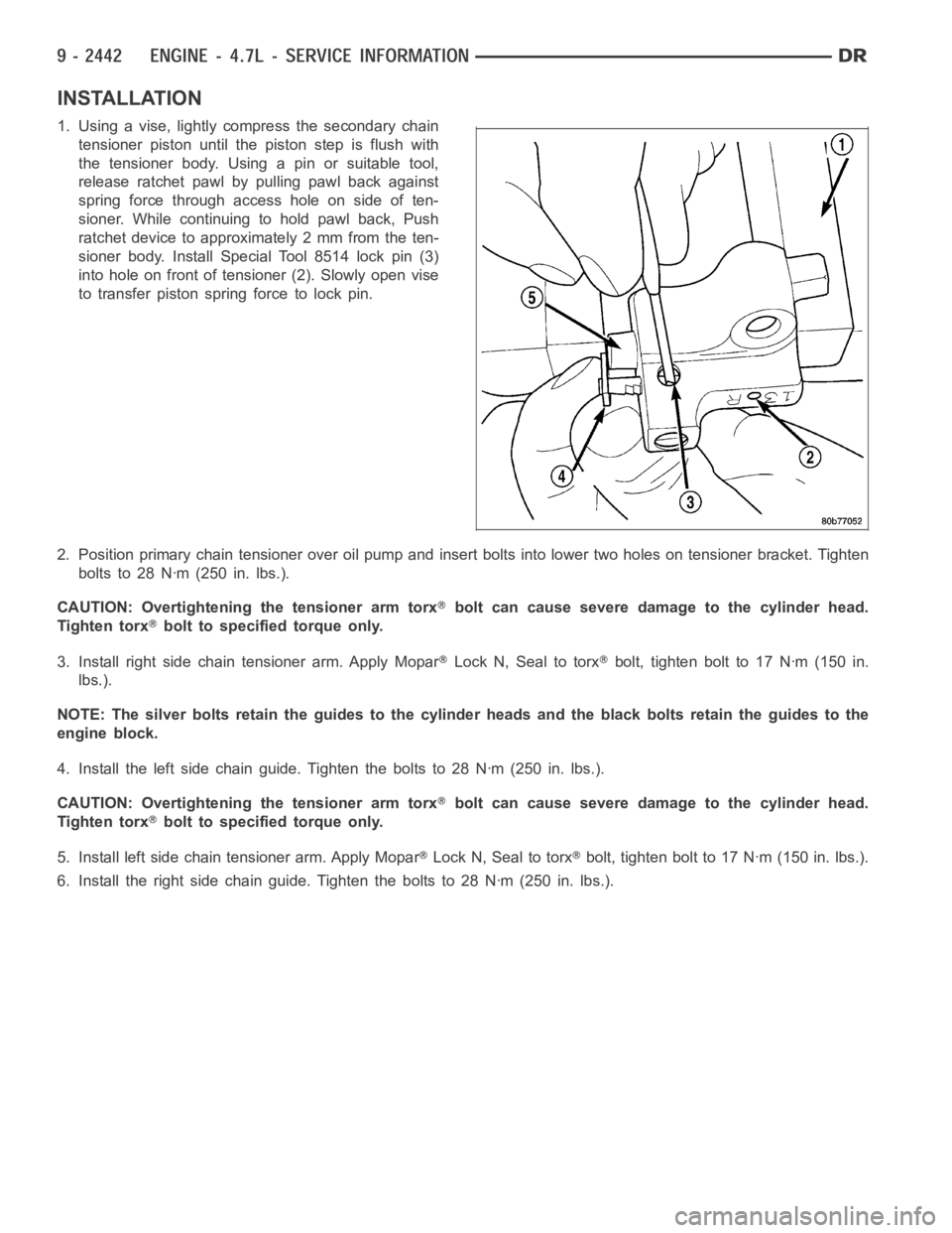
1. Using a vise, lightly compress the secondary chain
tensioner piston until the piston step is flush with
the tensioner body. Using a pin or suitable tool,
release ratchet pawl by pulling pawl back against
spring force through access hole on side of ten-
sioner. While continuing to hold pawl back, Push
ratchet device to approximately 2 mm from the ten-
sioner body. Install Special Tool 8514 lock pin (3)
into hole on front of tensioner (2). Slowly open vise
to transfer piston spring force to lock pin.
2. Position primary chain tensioner over oil pump and insert bolts into lower two holes on tensioner bracket. Tighten
bolts to 28 Nꞏm (250 in. lbs.).
CAUTION: Overtightening the tensioner arm torx
bolt can cause severe damage to the cylinder head.
Tighten torx
bolt to specified torque only.
3. Install right side chain tensioner arm. Apply Mopar
Lock N, Seal to torxbolt, tighten bolt to 17 Nꞏm (150 in.
lbs.).
NOTE: The silver bolts retain the guides to the cylinder heads and the blackbolts retain the guides to the
engine block.
4. Install the left side chain guide. Tighten the bolts to 28 Nꞏm (250 in. lbs.).
CAUTION: Overtightening the tensioner arm torx
bolt can cause severe damage to the cylinder head.
Tighten torx
bolt to specified torque only.
5. Install left side chain tensioner arm. Apply Mopar
Lock N, Seal to torxbolt, tighten bolt to 17 Nꞏm (150 in. lbs.).
6. Install the right side chain guide. Tighten the bolts to 28 Nꞏm (250 in. lbs.).
Page 1752 of 5267
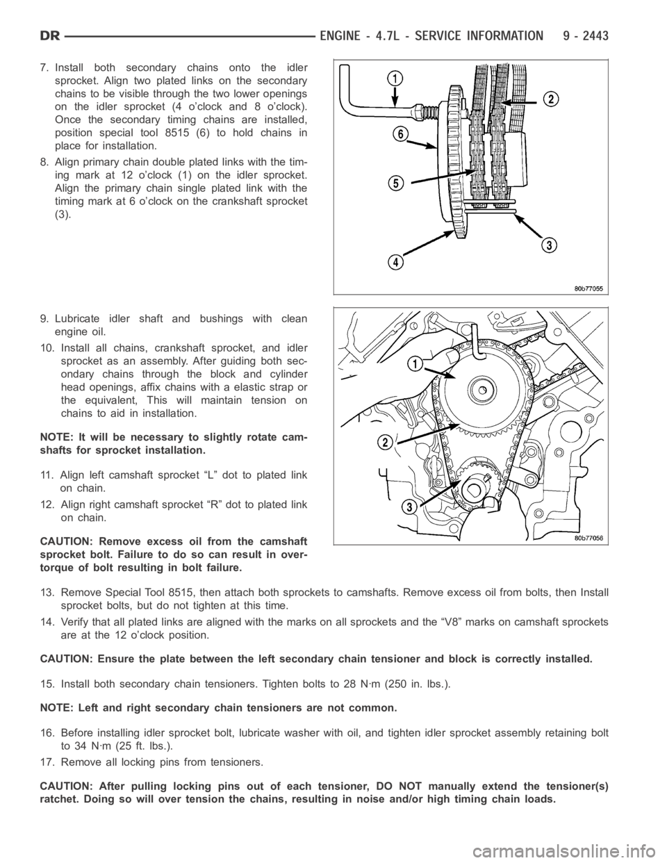
7. Install both secondary chains onto the idler
sprocket. Align two plated links on the secondary
chains to be visible through the two lower openings
on the idler sprocket (4 o’clock and 8 o’clock).
Once the secondary timing chains are installed,
position special tool 8515 (6) to hold chains in
place for installation.
8. Align primary chain double plated links with the tim-
ingmarkat12o’clock(1)ontheidlersprocket.
Align the primary chain single plated link with the
timing mark at 6 o’clock on the crankshaft sprocket
(3).
9. Lubricate idler shaft and bushings with clean
engine oil.
10. Install all chains, crankshaft sprocket, and idler
sprocket as an assembly. After guiding both sec-
ondary chains through the block and cylinder
head openings, affix chains with a elastic strap or
the equivalent, This will maintain tension on
chains to aid in installation.
NOTE: It will be necessary to slightly rotate cam-
shafts for sprocket installation.
11. Align left camshaft sprocket “L” dot to plated link
on chain.
12. Align right camshaft sprocket “R” dot to plated link
on chain.
CAUTION: Remove excess oil from the camshaft
sprocket bolt. Failure to do so can result in over-
torque of bolt resulting in bolt failure.
13. Remove Special Tool 8515, then attach both sprockets to camshafts. Remove excess oil from bolts, then Install
sprocket bolts, but do not tighten at this time.
14. Verify that all plated links are aligned with the marks on all sprocketsand the “V8” marks on camshaft sprockets
are at the 12 o’clock position.
CAUTION: Ensure the plate between the left secondary chain tensioner and block is correctly installed.
15. Install both secondary chain tensioners. Tighten bolts to 28 Nꞏm (250 in. lbs.).
NOTE: Left and right secondary chain tensioners are not common.
16. Before installing idler sprocketbolt, lubricate washer with oil, andtighten idler sprocket assembly retaining bolt
to 34 Nꞏm (25 ft. lbs.).
17. Remove all locking pins from tensioners.
CAUTION: After pulling locking pins out of each tensioner, DO NOT manuallyextend the tensioner(s)
ratchet. Doing so will over tension thechains, resulting in noise and/or high timing chain loads.
Page 1758 of 5267
ENGINE - 5.7L - SERVICE INFORMATION
DESCRIPTION
The 5.7L engine (345 CID) eight-cylinder engine is a 90° V-Type lightweight, deep skirt cast iron block, aluminum
heads, single cam, overhead valve engine with hydraulic roller tappets. The heads incorporate splayed valves with
a hemispherical style combustion chamber and dual spark plugs. The cylinders are numbered from front to rear; 1,
3, 5, 7 on the left bank and 2, 4, 6, 8 on the right bank. The firing order is 1-8-4-3-6-5-7-2.
DIAGNOSIS AND TESTING
DIAGNOSIS AND TESTING - ENGINE DIAGNOSIS - INTRODUCTION
Engine diagnosis is helpful in determining the causes of malfunctions notdetected and remedied by routine main-
tenance.
These malfunctions may be classified as either performance (e.g., engineidles rough and stalls) or mechanical
(e.g., a strange noise).
(Refer to 9 - ENGINE - DIAGNOSIS AND TESTING) - PERFORMANCE and (Refer to 9 - ENGINE - DIAGNOSIS
AND TESTING)—MECHANICAL for possible causes and corrections of malfunctions. (Refer to 14 - FUEL SYSTEM/
FUEL DELIVERY - DIAGNOSIS AND TESTING) and (Refer to 14 - FUEL SYSTEM/FUEL INJECTION - DIAGNO-
SIS AND TESTING) for the fuel system diagnosis.
Additional tests and diagnostic procedures may be necessary for specificengine malfunctions that can not be iso-
lated with the Service Diagnosis charts. Information concerning additional tests and diagnosis is provided within the
following diagnosis:
Cylinder Compression Pressure Test (Refer to 9 - ENGINE - DIAGNOSIS AND TESTING).
Cylinder Combustion Pressure LeakageTest (Refer to 9 - ENGINE - DIAGNOSISAND TESTING).
Engine Cylinder Head Gasket Failure Diagnosis (Refer to 9 - ENGINE/CYLINDER HEAD - DIAGNOSIS AND
TESTING).
Intake Manifold Leakage Diagnosis (Refer to 9 - ENGINE/MANIFOLDS/INTAKEMANIFOLD - DIAGNOSIS
AND TESTING).
DIAGNOSIS AND TESTING - ENGINE DIAGNOSIS - PERFORMANCE
CONDITION POSSIBLE CAUSE CORRECTION
ENGINE WILL NOT START 1. Weak battery 1. Charge or replace as necessary.
2. Corroded or loose battery
connections.2. Clean and tighten battery
connections. Apply a coat of light
mineral grease to the terminals.
3. Faulty starter. 3. (Refer to 8 - ELECTRICAL/
STARTING - DIAGNOSIS AND
TESTING).
4. Faulty coil or control unit. 4. (Refer to 8 - ELECTRICAL/
IGNITION CONTROL/IGNITION
COIL - REMOVAL).
5. Incorrect spark plug gap. 5. (Refer to 8 - ELECTRICAL/
IGNITION CONTROL/SPARK PLUG
- CLEANING).
6. Dirt or water in fuel system. 6. Clean system and replace fuel
filter.
7. Faulty fuel pump, relay or wiring. 7. Repair or replace as necessary.
Page 1805 of 5267
VALVES & SEATS - INTAKE/EXHAUST
DESCRIPTION
DESCRIPTION - VALVE GUIDES
The valve guides are made of powdered metal and are pressed into the cylinder head. The guides are not replace-
able or serviceable, and valve guide reaming is not recommended. If the guides are worn beyond acceptable limits,
replace the cylinder heads.
DESCRIPTION
Both the intake and exhaust valves are made of steel. The intake valve is 50.93 mm (2.00 inches) in diameter and
the exhaust valve is 39.53 mm (1.55 inches) in diameter. All valves use three bead lock keepers to retain the
springs and promote valve rotation.
STANDARD PROCEDURE - REFACING
NOTE: Valve seats that are worn or burned can be reworked, provided that correct angle and seat width are
maintained. Otherwise the cylinder head must be replaced.
NOTE: When refacing valves and valve seats, it is important that the correct size valve guide pilot be used
for reseating stones. A true and complete surface must be obtained.
1. Using a suitable dial indicator measure the center of the valve seat Total run out must not exceed 0.051 mm
(0.002 in).
2. Apply a small amount of Prussian blue to the valve seat, insert the valve into the cylinder head, while applying
light pressure on the valve rotate the valve. Remove the valve and examine the valve face. If the blue is trans-
ferred below the top edge of the valve face, lower the valve seat using a 15 degree stone. If the blue is trans-
ferred to the bottom edge of the valve face, raise the valve seat using a 65 degree stone.
3. When the seat is properly positioned the width of the intake seat must be 1.018 - 1.62 mm (0.0464 - 0.0637 in.)
and the exhaust seat must be 1.48 - 1.92 mm (0.058 - 0.075 in.).
4. Check the valve spring installed height after refacing the valve and seat.Theinstalledheightforbothintakeand
exhaust valve springs must not exceed 46.0 mm (1.81 in.).
VALVE FACE AND VALVE SEAT ANGLE CHART
DESCRIPTION SPECIFICATION
SEAT WIDTH
INTAKE 1.018 - 1.62 mm
(0.0464 - 0.0637 in.)
EXHAUST 1.48 - 1.92 mm
(0.058 - 0.075 in.)
FA C E A N G L E
(INT. AND EXT.) 45° - 45
1⁄2°
SEAT ANGLE
(INT. AND EXT.) 44
1⁄2° - 45°
Page 1824 of 5267
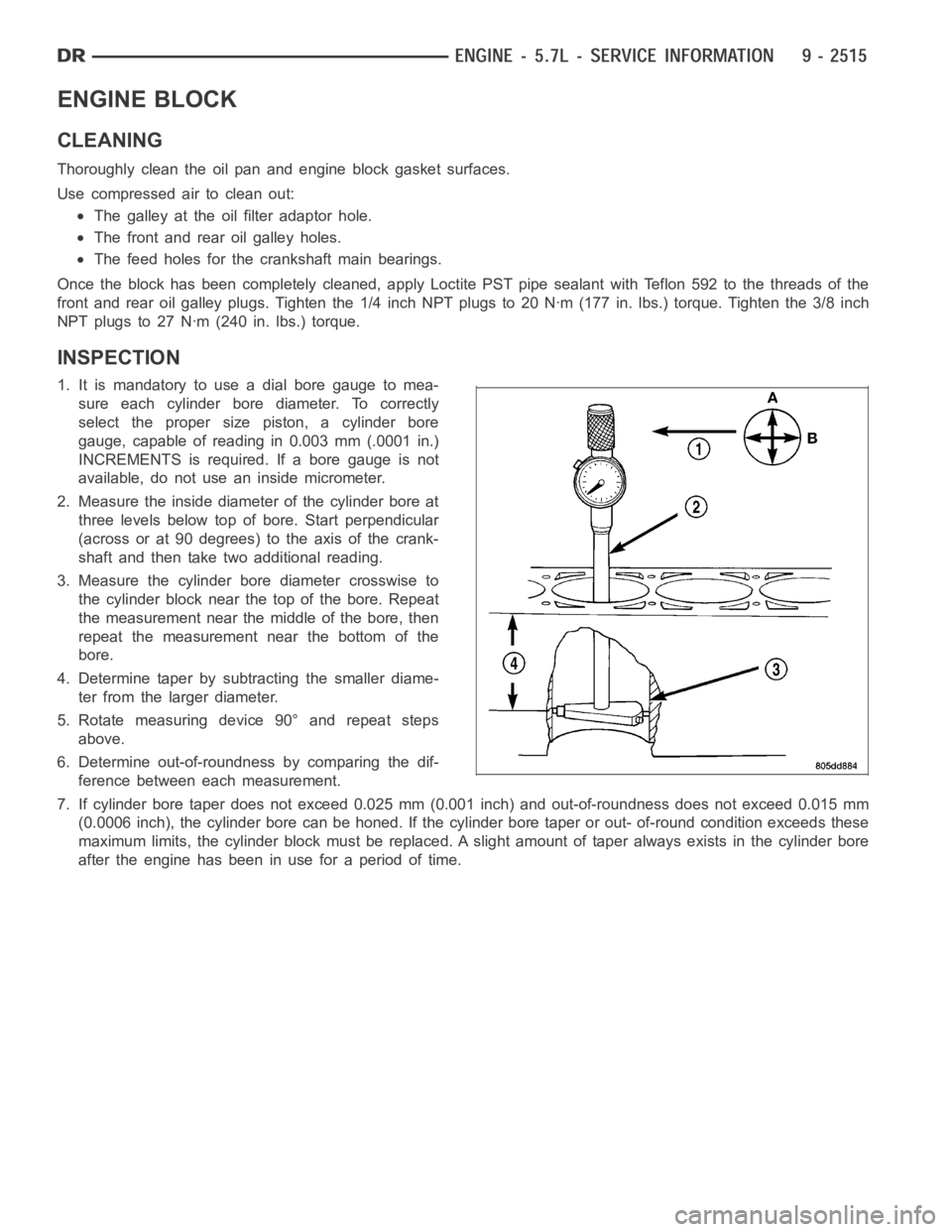
ENGINE BLOCK
CLEANING
Thoroughly clean the oil pan and engine block gasket surfaces.
Use compressed air to clean out:
The galley at the oil filter adaptor hole.
The front and rear oil galley holes.
The feed holes for the crankshaft main bearings.
Once the block has been completely cleaned, apply Loctite PST pipe sealantwith Teflon 592 to the threads of the
front and rear oil galley plugs. Tighten the 1/4 inch NPT plugs to 20 Nꞏm (177in. lbs.) torque. Tighten the 3/8 inch
NPT plugs to 27 Nꞏm (240 in. lbs.) torque.
INSPECTION
1. It is mandatory to use a dial bore gauge to mea-
sure each cylinder bore diameter. To correctly
select the proper size piston, a cylinder bore
gauge, capable of reading in 0.003 mm (.0001 in.)
INCREMENTS is required. If a bore gauge is not
available, do not use an inside micrometer.
2. Measure the inside diameter of the cylinder bore at
three levels below top of bore. Start perpendicular
(across or at 90 degrees) to the axis of the crank-
shaft and then take two additional reading.
3. Measure the cylinder bore diameter crosswise to
the cylinder block near the top of the bore. Repeat
the measurement near the middle of the bore, then
repeat the measurement near the bottom of the
bore.
4. Determine taper by subtracting the smaller diame-
ter from the larger diameter.
5. Rotate measuring device 90° and repeat steps
above.
6. Determine out-of-roundness by comparing the dif-
ference between each measurement.
7. If cylinder bore taper does not exceed 0.025 mm (0.001 inch) and out-of-roundness does not exceed 0.015 mm
(0.0006 inch), the cylinder bore can be honed. If the cylinder bore taper orout- of-round condition exceeds these
maximum limits, the cylinder block must be replaced. A slight amount of taper always exists in the cylinder bore
after the engine has been in use for a period of time.
Page 1848 of 5267
SEAL - CRANKSHAFT OIL - REAR
DIAGNOSIS AND TESTING - REAR SEAL AREA LEAKS
Since it is sometimes difficult to determine the source of an oil leak in therear seal area of the engine, a more
involved inspection is necessary. The following steps should be followedto help pinpoint the source of the leak.
If the leakage occurs at the crankshaft rear oil seal area:
1. Disconnect the battery.
2. Raise the vehicle.
3. Remove torque converter or clutch housing cover and inspect rear of block for evidence of oil. Use a black light
to check for the oil leak:
a. Circular spray pattern generally indicates seal leakage or crankshaftdamage.
b. Where leakage tends to run straight down, possible causes are a porous block, camshaft bore cup plugs, oil
galley pipe plugs, oil filter runoff, and main bearing cap to cylinder block mating surfaces. See Engine, for
proper repair procedures of these items.
4. If no leaks are detected, pressurized the crankcase as outlined in the section, Inspection (Engine oil Leaks in
general)
CAUTION: Do not exceed 20.6 kPa (3 psi).
5. If the leak is not detected, very slowly turn the crankshaft and watch forleakage. If a leak is detected between
the crankshaft and seal while slowly turning the crankshaft, it is possible the crankshaft seal surface is damaged.
The seal area on the crankshaft could have minor nicks or scratches that canbe polished out with emery cloth.
CAUTION: Use extreme caution when crankshaft polishing is necessary to remove minor nicks or
scratches. The crankshaft seal flange is specially machined to complement the function of the rear oil seal.
6. For bubbles that remain steady with shaft rotation, no further inspection can be done until disassembled. (Refer
to 9 - ENGINE - DIAGNOSIS AND TESTING), under the Oil Leak row, for components inspections on possible
causes and corrections.
7. After the oil leak root cause and appropriate corrective action have been identified, (Refer to 9 - ENGINE/EN-
GINE BLOCK/CRANKSHAFT OIL SEAL - REAR - REMOVAL).
REMOVAL
NOTE: This procedure can be performed in vehi-
cle.
1. If being performed in vehicle, remove the transmis-
sion.
2. Remove the flexplate (Refer to 9 - ENGINE/EN-
GINE BLOCK/FLEX PLATE - REMOVAL).
NOTE: The crankshaft oil seal CAN NOT be reused
after removal.
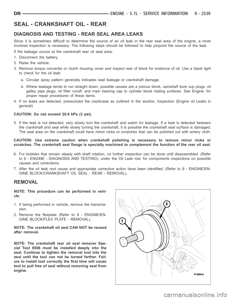
NOTE: The crankshaft rear oil seal remover Spe-
cial Tool 8506 must be installed deeply into the
seal. Continue to tighten the removal tool into the
seal until the tool can not be turned farther. Fail-
ure to install tool correctly the first time will cause
tool to pull free of seal without removing seal from
engine.
Page 1852 of 5267
TAPPETS - HYDRAULIC ROLLER
DIAGNOSIS AND TESTING - HYDRAULIC TAPPETS
Before disassembling any part of the engine to correct tappet noise, checkthe oil pressure. If vehicle has no oil
pressure gauge, install a reliable gauge at the pressure sending-unit. The pressure should be between 207-552 kPa
(30-70 psi) at 3,000 RPM.
Check the oil level after the engine reaches normal operating temperature. Allow 5 minutes to stabilize oil level,
check dipstick. The oil level in the pan should never be above the FULL mark or below the ADD OIL mark on
dipstick. Either of these two conditions could be responsible for noisy tappets.
OIL LEVEL
HIGH
If oil level is above the FULL mark, it is possible for the connecting rods todip into the oil. With the engine running,
this condition could create foam in the oil pan. Foam in oil pan would be fed to the hydraulic tappets by the oil pump
causing them to lose length and allow valves to seat noisily.
LOW
Low oil level may allow oil pump to take in air. When air is fed to the tappets,they lose length, which allows valves
to seat noisily. Any leaks on intake side of oil pump through which air can bedrawn will create the same tappet
action. Check the lubrication system from the intake strainer to the pump cover, including the relief valve retainer
cap. When tappet noise is due to aeration, it may be intermittent or constant, and usually more than one tappet will
be noisy. When oil level and leaks have been corrected, operate the engine at fast idle. Run engine for a sufficient
time to allow all of the air inside the tappets to be bled out.
TAPPET NOISE DIAGNOSIS
1. To determine source of tappet noise, crank over engine with cylinder head covers removed.
2. Feel each valve spring or rocker arm to detect noisy tappet. The noisy tappet will cause the affected spring
and/or rocker arm to vibrate or feel rough in operation.
NOTE: Worn valve guides or cocked springs are sometimes mistaken for noisytappets. If such is the case,
noise may be dampened by applying side thrust on the valve spring. If noise is not appreciably reduced, it
can be assumed the noise is in the tappet. Inspect the rocker arm push rod sockets and push rod ends for
wear.
3. Valve tappet noise ranges from light noise to a heavy click. A light noiseis usually caused by excessive leak-
down around the unit plunger, or by the plunger partially sticking in the tappet body cylinder. The tappet should
be replaced. A heavy click is caused by a tappet check valve not seating, or by foreign particles wedged between
the plunger and the tappet body. This will cause the plunger to stick in the down position. This heavy click will be
accompanied by excessive clearance between the valve stem and rocker arm as valve closes. In either case,
tappet assembly should be removed for inspection and cleaning.
4. The valve train generates a noise very much like a light tappet noise during normal operation. Care must be
taken to ensure that tappets are making the noise. If more than one tappet seems to be noisy, it’s probably not
the tappets.
REMOVAL
1. Disconnect the negative cable from the battery.
2. Remove the air cleaner (Refer to 9 - ENGINE/AIR INTAKE SYSTEM - REMOVAL).
3. Remove intake manifold (Refer to 9 - ENGINE/MANIFOLDS/INTAKE MANIFOLD-REMOVAL).
4. Remove cylinder head cover (Refer to 9 - ENGINE/CYLINDER HEAD/CYLINDERHEAD COVER(S) -
REMOVAL).
5. Remove rocker arm assembly and push rods (Refer to 9 - ENGINE/CYLINDER HEAD/ROCKER ARM /
ADJUSTER ASSY - REMOVAL). Identify push rods to ensure installation in original location.
6. Remove the cylinder head (Refer to 9 - ENGINE/CYLINDER HEAD - REMOVAL).
Page 1856 of 5267
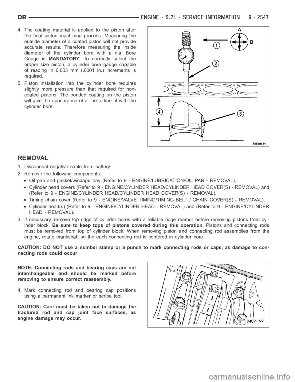
4. The coating material is applied to the piston after
the final piston machining process. Measuring the
outside diameter of a coated piston will not provide
accurate results. Therefore measuring the inside
diameter of the cylinder bore with a dial Bore
Gauge isMANDATORY. To correctly select the
proper size piston, a cylinder bore gauge capable
of reading in 0.003 mm (.0001 in.) increments is
required.
5. Piston installation intothe cylinder bore requires
slightly more pressure than that required for non-
coated pistons. The bonded coating on the piston
will give the appearance of a line-to-line fit with the
cylinder bore.
REMOVAL
1. Disconnect negative cable from battery.
2. Remove the following components:
Oil pan and gasket/windage tray (Refer to 9 - ENGINE/LUBRICATION/OIL PAN -REMOVAL).
Cylinder head covers (Refer to 9 - ENGINE/CYLINDER HEAD/CYLINDER HEAD COVER(S) - REMOVAL) and
(Refer to 9 - ENGINE/CYLINDER HEAD/CYLINDER HEAD COVER(S) - REMOVAL).
Timing chain cover (Refer to 9 - ENGINE/VALVE TIMING/TIMING BELT / CHAIN COVER(S) - REMOVAL).
Cylinder head(s) (Refer to 9 - ENGINE/CYLINDER HEAD - REMOVAL) and (Refer to 9 - ENGINE/CYLINDER
HEAD - REMOVAL).
3. If necessary, remove top ridge of cylinder bores with a reliable ridge reamer before removing pistons from cyl-
inder block.Be sure to keep tops of pistons covered during this operation.Pistons and connecting rods
must be removed from top of cylinder block. When removing piston and connecting rod assemblies from the
engine, rotate crankshaft so the each connecting rod is centered in cylinder bore.
CAUTION: DO NOT use a number stamp or a punch to mark connecting rods or caps,as damage to con-
necting rods could occur
NOTE: Connecting rods and bearing caps are not
interchangeable and should be marked before
removing to ensure correct reassembly.
4. Mark connecting rod and bearing cap positions
using a permanent ink marker or scribe tool.
CAUTION: Care must be taken not to damage the
fractured rod and cap joint face surfaces, as
engine damage may occur.