2006 DODGE RAM SRT-10 light
[x] Cancel search: lightPage 1863 of 5267
DAMPER - CRANKSHAFT
REMOVAL
1. Disconnect negative cable from battery.
2. Remove accessory drive belt (Refer to 7 - COOLING/ACCESSORY DRIVE/DRIVE BELTS - REMOVAL).
3. Drain cooling system (Refer to 7 - COOLING - STANDARD PROCEDURE).
4. Remove radiator upper hose.
5. Removefanshroud(Referto7-COOLING/ENGINE/RADIATOR FAN - REMOVAL).
6. Remove crankshaft damper bolt.
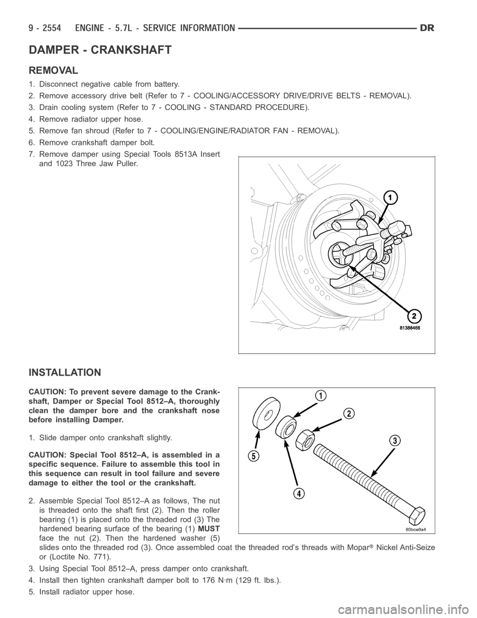
7. Remove damper using Special Tools 8513A Insert
and 1023 Three Jaw Puller.
INSTALLATION
CAUTION: To prevent severe damage to the Crank-
shaft, Damper or Special Tool 8512–A, thoroughly
clean the damper bore and the crankshaft nose
before installing Damper.
1. Slide damper onto crankshaft slightly.
CAUTION: Special Tool 8512–A, is assembled in a
specific sequence. Failure to assemble this tool in
this sequence can result in tool failure and severe
damage to either the tool or the crankshaft.
2. Assemble Special Tool 8512–A as follows, The nut
is threaded onto the shaft first (2). Then the roller
bearing (1) is placed onto the threaded rod (3) The
hardened bearing surface of the bearing (1)MUST
face the nut (2). Then the hardened washer (5)
slides onto the threaded rod (3). Once assembled coat the threaded rod’s threads with Mopar
Nickel Anti-Seize
or (Loctite No. 771).
3. Using Special Tool 8512–A, press damper onto crankshaft.
4. Install then tighten crankshaft damper bolt to 176 Nꞏm (129 ft. lbs.).
5. Install radiator upper hose.
Page 1875 of 5267
LUBRICATION
DIAGNOSIS AND TESTING
DIAGNOSIS AND TESTING - CHECKING ENGINE OIL PRESSURE
1. Remove oil pressure sending unit and install gauge assembly C-3292.
2. Run engine until thermostat opens.
3. Oil Pressure:
Curb Idle–25 kPa (4 psi) minimum
3000 rpm–170 - 758 kPa (25 - 110 psi)
4. If oil pressure is 0 at idle, shut off engine. Check for a clogged oil pick-up screen or a pressure relief valve stuck
open.
DIAGNOSIS AND TESTING - ENGINE OIL LEAK
Begin with a thorough visual inspection of the engine, particularly at thearea of the suspected leak. If an oil leak
source is not readily identifiable, thefollowingstepsshouldbefollowed:
1. Do not clean or degrease the engine at this time because some solvents maycause rubber to swell, temporarily
stopping the leak.
2. Add an oil soluble dye (use as recommended by manufacturer). Start the engine and let idle for approximately 15
minutes. Check the oil dipstick to make sure the dye is thoroughly mixed as indicated with a bright yellow color
under a black light.
3. Using a black light, inspect the entire engine for fluorescent dye, particularly at the suspected area of oil leak. If
the oil leak is found and identified, repair per service manual instructions.
4. If dye is not observed, drive the vehicle at various speeds for approximately 24 km (15 miles), and repeat inspec-
tion.If the oil leak source is not positively identified at this time, proceed with the air leak detection test
method.
Air Leak Detection Test Method
1. Remove the PCV valve from the IAFM. Cap or plug the PCV valve grommet.
2. Attach an air hose with pressure gauge and regulator to the dipstick tube.
CAUTION: Do not subject the engine assembly to more than 20.6 kPa (3 PSI) of test pressure.
3. Gradually apply air pressure from 1 psi to 2.5 psi maximum while applyingsoapy water at the suspected source.
Adjust the regulator to the suitable test pressure that provide the best bubbles which will pinpoint the leak
source. If the oil leak is detected and identified, repair per service manual procedures.
4. If the leakage occurs at the rear oil seal area, refer to the section, Inspection for Rear Seal Area Leak.
5. If no leaks are detected, turn off the air supply and remove the air hose and all plugs and caps. Install the PCV
valve.
6. Clean the oil off the suspect oil leak area using a suitable solvent. Drive the vehicle at various speeds approx-
imately 24 km (15 miles). Inspect the engine for signs of an oil leak by usinga black light.
INSPECTION FOR REAR SEAL AREA LEAKS
Since it is sometimes difficult to determine the source of an oil leak in therear seal area of the engine, a more
involved inspection is necessary. The following steps should be followedto help pinpoint the source of the leak.
If the leakage occurs at the crankshaft rear oil seal area:
1. Disconnect the battery.
2. Raise the vehicle.
3. Remove torque converter or clutch housing cover and inspect rear of block for evidence of oil. Use a black light
to check for the oil leak:
a. Circular spray pattern generally indicates seal leakage or crankshaftdamage.
Page 1878 of 5267
FILTER - ENGINE OIL
REMOVAL
All engines are equipped with a high quality full-flow,
disposable type oil filter. DaimlerChrysler Corporation
recommends a Mopar
or equivalent oil filter be used.
1. Position a drain pan under the oil filter.
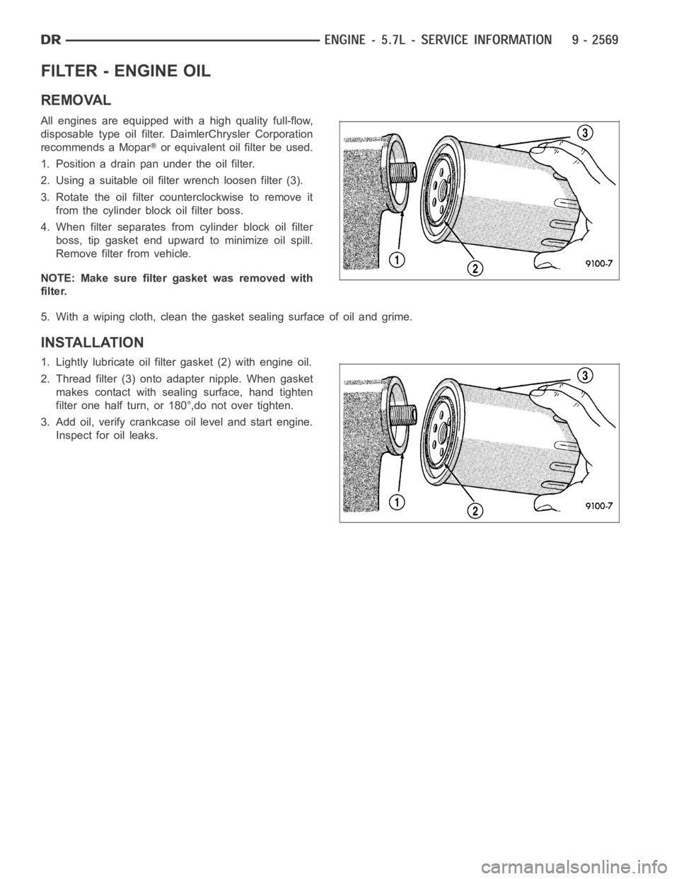
2. Using a suitable oil filter wrench loosen filter (3).
3. Rotate the oil filter counterclockwise to remove it
from the cylinder block oil filter boss.
4. When filter separates from cylinder block oil filter
boss, tip gasket end upward to minimize oil spill.
Remove filter from vehicle.
NOTE: Make sure filter gasket was removed with
filter.
5. With a wiping cloth, clean the gasket sealing surface of oil and grime.
INSTALLATION
1. Lightly lubricate oil filter gasket (2) with engine oil.
2. Thread filter (3) onto adapter nipple. When gasket
makes contact with sealing surface, hand tighten
filter one half turn, or 180°,do not over tighten.
3. Add oil, verify crankcase oil level and start engine.
Inspect for oil leaks.
Page 1889 of 5267
MANIFOLD - EXHAUST
DESCRIPTION
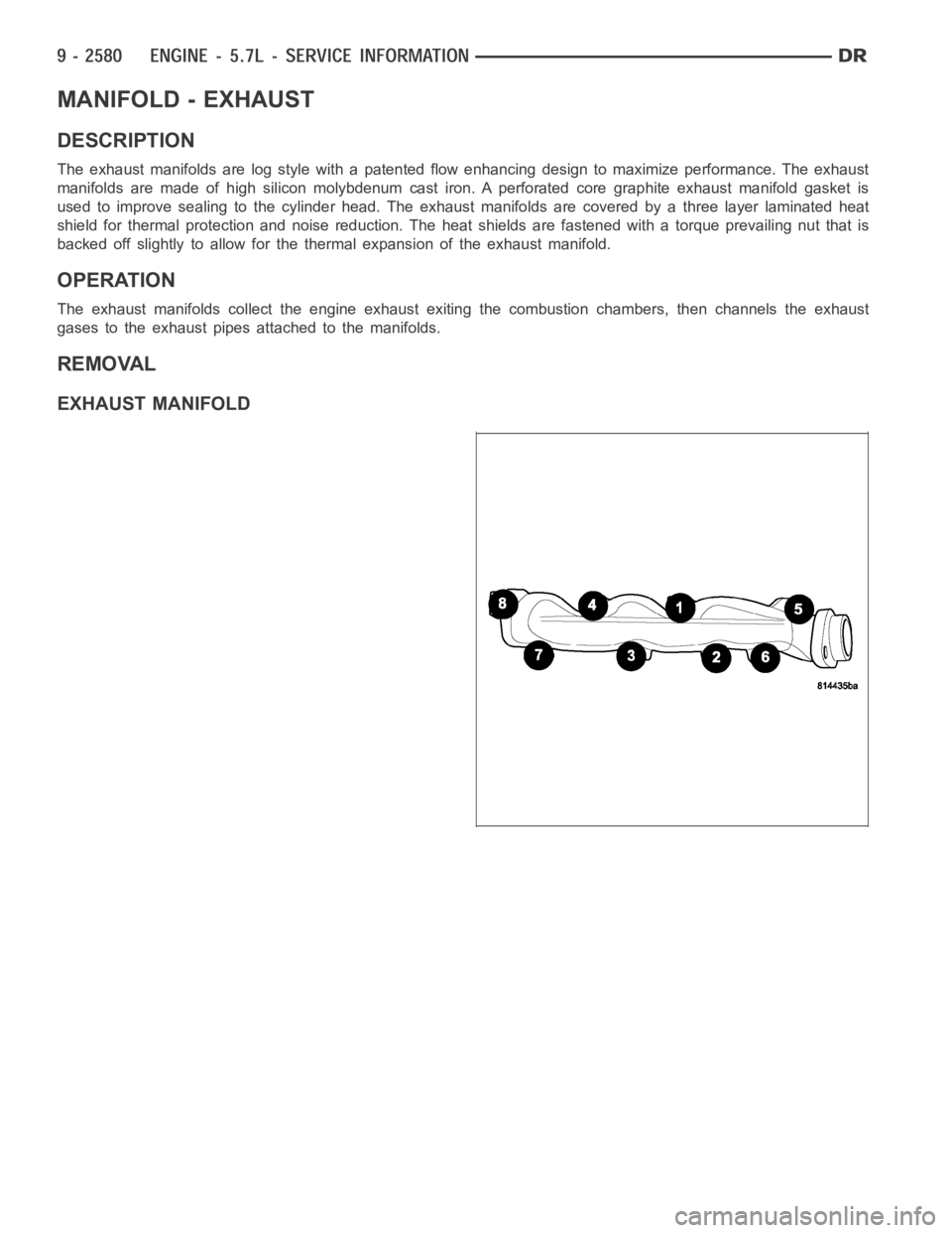
The exhaust manifolds are log style with a patented flow enhancing design to maximize performance. The exhaust
manifolds are made of high silicon molybdenum cast iron. A perforated coregraphite exhaust manifold gasket is
used to improve sealing to the cylinder head. The exhaust manifolds are covered by a three layer laminated heat
shield for thermal protection and noise reduction. The heat shields are fastened with a torque prevailing nut that is
backed off slightly to allow for the thermal expansion of the exhaust manifold.
OPERATION
The exhaust manifolds collect the engine exhaust exiting the combustion chambers, then channels the exhaust
gases to the exhaust pipes attached to the manifolds.
REMOVAL
EXHAUST MANIFOLD
Page 1937 of 5267
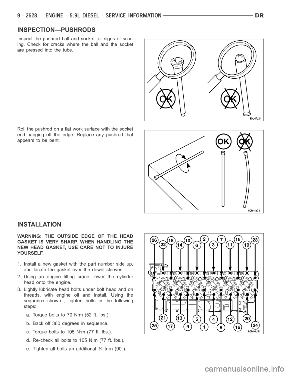
INSPECTION—PUSHRODS
Inspect the pushrod ball and socket for signs of scor-
ing. Check for cracks where the ball and the socket
are pressed into the tube.
Roll the pushrod on a flat work surface with the socket
end hanging off the edge. Replace any pushrod that
appears to be bent.
INSTALLATION
WARNING: THE OUTSIDE EDGE OF THE HEAD
GASKET IS VERY SHARP. WHEN HANDLING THE
NEW HEAD GASKET, USE CARE NOT TO INJURE
YOURSELF.
1. Install a new gasket with the part number side up,
and locate the gasket over the dowel sleeves.
2. Using an engine lifting crane, lower the cylinder
head onto the engine.
3. Lightly lubricate head bolts under bolt head and on
threads, with engine oil and install. Using the
sequence shown , tighten bolts in the following
steps:
a. Torqueboltsto70Nꞏm(52ft.lbs.).
b. Back off 360 degrees in sequence.
c. Torque bolts to 105 Nꞏm (77 ft. lbs.).
d. Re-check all bolts to 105 Nꞏm (77 ft. lbs.).
e. Tighten all bolts an additional
1⁄4turn (90°).
Page 1961 of 5267
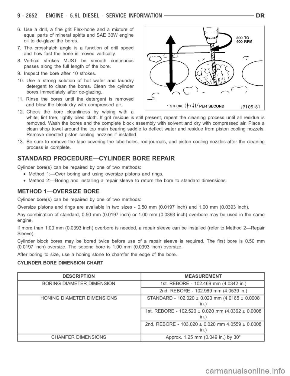
6. Use a drill, a fine grit Flex-hone and a mixture of
equal parts of mineral spirits and SAE 30W engine
oil to de-glaze the bores.
7. The crosshatch angle is a function of drill speed
and how fast the hone is moved vertically.
8. Vertical strokes MUST be smooth continuous
passes along the full length of the bore.
9. Inspect the bore after 10 strokes.
10. Use a strong solution of hot water and laundry
detergent to clean the bores. Clean the cylinder
bores immediately after de-glazing.
11. Rinse the bores until the detergent is removed
and blow the block dry with compressed air.
12. Check the bore cleanliness by wiping with a
white, lint free, lightly oiled cloth. If grit residue is still present, repeat the cleaning process until all residue is
removed. Wash the bores and the complete block assembly with solvent and dry with compressed air. Place a
clean shop towel around the top main bearing saddle to deflect water and residue from piston cooling nozzels.
Remove directed piston cooling nozzles if installed.
13. Be sure to remove the tape covering the lube holes, rod journals, and piston cooling nozzles after the cleaning
process is complete.
STANDARD PROCEDURE—CYLINDER BORE REPAIR
Cylinder bore(s) can be repaired by one of two methods:
Method 1:—Over boring and using oversize pistons and rings.
Method 2:—Boring and installing a repair sleeve to return the bore to standard dimensions.
METHOD 1—OVERSIZE BORE
Cylinder bore(s) can be repaired by one of two methods:
Oversize pistons and rings are available in two sizes - 0.50 mm (0.0197 inch) and 1.00 mm (0.0393 inch).
Any combination of standard, 0.50 mm (0.0197 inch) or 1.00 mm (0.0393 inch)overbore may be used in the same
engine.
If more than 1.00 mm (0.0393 inch) overbore is needed, a repair sleeve can beinstalled (refer to Method 2—Repair
Sleeve).
Cylinder block bores may be bored twice before use of a repair sleeve is required. The first bore is 0.50 mm
(0.0197 inch) oversize. The second bore is 1.00 mm (0.0393 inch) oversize.
After boring to size, use a honing stone to chamfer the edge of the bore.
CYLINDER BORE DIMENSION CHART
DESCRIPTION MEASUREMENT
BORING DIAMETER DIMENSION 1st. REBORE - 102.469 mm (4.0342 in.)
2nd. REBORE - 102.969 mm (4.0539 in.)
HONING DIAMETER DIMENSIONS STANDARD - 102.020 ± 0.020 mm (4.0165 ± 0.0008
in.)
1st. REBORE - 102.520 ± 0.020 mm (4.0362 ± 0.0008
in.)
2nd. REBORE - 103.020 ± 0.020 mm 4.0559 ± 0.0008
in.)
CHAMFER DIMENSIONS Approx. 1.25 mm (0.049 in.) by 30°
Page 1962 of 5267
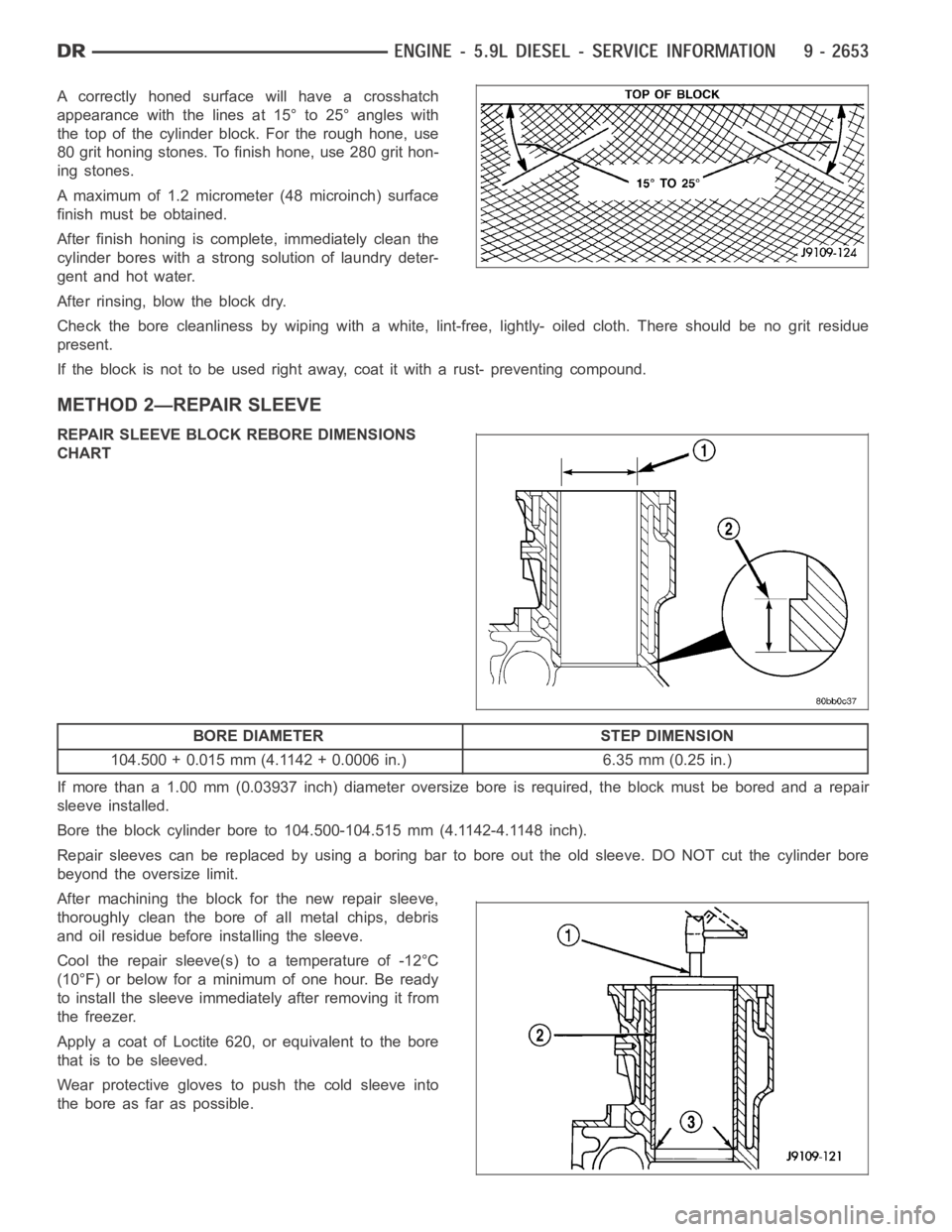
A correctly honed surface will have a crosshatch
appearance with the lines at 15° to 25° angles with
the top of the cylinder block. For the rough hone, use
80 grit honing stones. To finish hone, use 280 grit hon-
ing stones.
A maximum of 1.2 micrometer (48 microinch) surface
finish must be obtained.
After finish honing is complete, immediately clean the
cylinder bores with a strong solution of laundry deter-
gent and hot water.
After rinsing, blow the block dry.
Check the bore cleanliness by wiping with a white, lint-free, lightly- oiled cloth. There should be no grit residue
present.
If the block is not to be used right away, coat it with a rust- preventing compound.
METHOD 2—REPAIR SLEEVE
REPAIR SLEEVE BLOCK REBORE DIMENSIONS
CHART
BORE DIAMETER STEP DIMENSION
104.500 + 0.015 mm (4.1142 + 0.0006 in.) 6.35 mm (0.25 in.)
If more than a 1.00 mm (0.03937 inch) diameter oversize bore is required, the block must be bored and a repair
sleeve installed.
Bore the block cylinder bore to 104.500-104.515 mm (4.1142-4.1148 inch).
Repair sleeves can be replaced by using a boring bar to bore out the old sleeve. DO NOT cut the cylinder bore
beyond the oversize limit.
After machining the block for the new repair sleeve,
thoroughly clean the bore of all metal chips, debris
and oil residue before installing the sleeve.
Cool the repair sleeve(s) to a temperature of -12°C
(10°F) or below for a minimum of one hour. Be ready
to install the sleeve immediately after removing it from
the freezer.
Apply a coat of Loctite 620, or equivalent to the bore
that is to be sleeved.
Wear protective gloves to push the cold sleeve into
the bore as far as possible.
Page 1963 of 5267
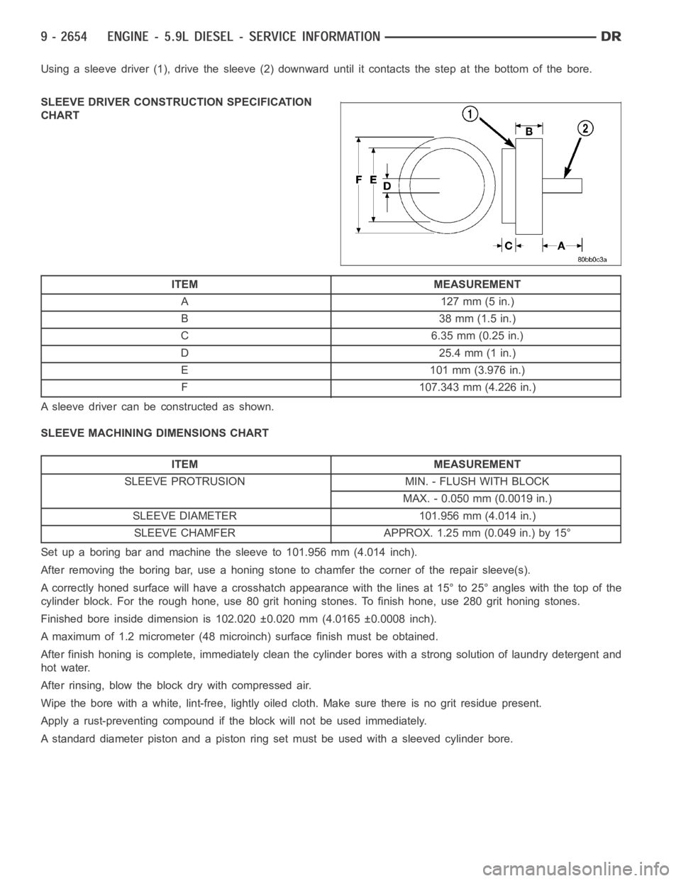
Using a sleeve driver (1), drive the sleeve (2) downward until it contacts the step at the bottom of the bore.
SLEEVE DRIVER CONSTRUCTION SPECIFICATION
CHART
ITEM MEASUREMENT
A127mm(5in.)
B 38mm(1.5in.)
C 6.35 mm (0.25 in.)
D 25.4 mm (1 in.)
E 101 mm (3.976 in.)
F 107.343 mm (4.226 in.)
A sleeve driver can be constructed as shown.
SLEEVE MACHINING DIMENSIONS CHART
ITEM MEASUREMENT
SLEEVE PROTRUSION MIN. - FLUSH WITH BLOCK
MAX. - 0.050 mm (0.0019 in.)
SLEEVE DIAMETER 101.956 mm (4.014 in.)
SLEEVE CHAMFER APPROX. 1.25 mm (0.049 in.) by 15°
Set up a boring bar and machine the sleeve to 101.956 mm (4.014 inch).
After removing the boring bar, use a honing stone to chamfer the corner of the repair sleeve(s).
A correctly honed surface will have a crosshatch appearance with the linesat 15° to 25° angles with the top of the
cylinder block. For the rough hone, use 80 grit honing stones. To finish hone, use 280 grit honing stones.
Finished bore inside dimension is 102.020 ±0.020 mm (4.0165 ±0.0008 inch).
A maximum of 1.2 micrometer (48 microinch) surface finish must be obtained.
After finish honing is complete, immediately clean the cylinder bores with a strong solution of laundry detergent and
hot water.
After rinsing, blow the block dry with compressed air.
Wipe the bore with a white, lint-free, lightly oiled cloth. Make sure thereis no grit residue present.
Apply a rust-preventing compound if the block will not be used immediately.
A standard diameter piston and a piston ring set must be used with a sleeved cylinder bore.