2006 DODGE RAM SRT-10 power steering
[x] Cancel search: power steeringPage 133 of 5267
3.SPEED CONTROL SWITCHES
Turn the ignition off.
Remove the Speed Control Switches from the steering wheel.
Measure the resistance across each Speed Control Switch.
Monitor the ohmmeter while pressing each function button on each switch.
The following resistance specs are taken between terminals (V38) S/C Switch No.2 Signal and (V937) S/C Switch
Return circuit of the Switch when holding the switch button in the following position.
On/Off - 8.87 kohms
Set - 0.825 kohms
Coast - 0.47 kohms
Cancel - 3.92 kohms
Resume/Accel - 1.87 kohms
The following resistance specs are taken between terminals (V37) S/C Switch No.1 Signal and (V937) S/C Switch
Return circuits of the Switch when holding the switch button in the following position
On/Off - 0.47 kohms
Set - 5.49 kohms
Coast - 2.94 kohms
Cancel - 1.24 kohms
Resume/Accel - 15.4 kohms
Does the function on the Speed Control Switches have the correct resistance value?
Ye s>>
Go To 4
No>>
Replace the Speed Control Switch that had the incorrect resistance value.
Perform the POWERTRAIN VERIFICATION TEST. (Refer to 9 - ENGINE - STANDARD PROCEDURE)
4.(V37) S/C SWITCH NO.1 SIGNAL CIRCUIT SHORTED TO BATTERY VOLTAGE
Turn the ignition off.
Disconnect the C3 PCM harness connector.
Ignition on, engine not running.
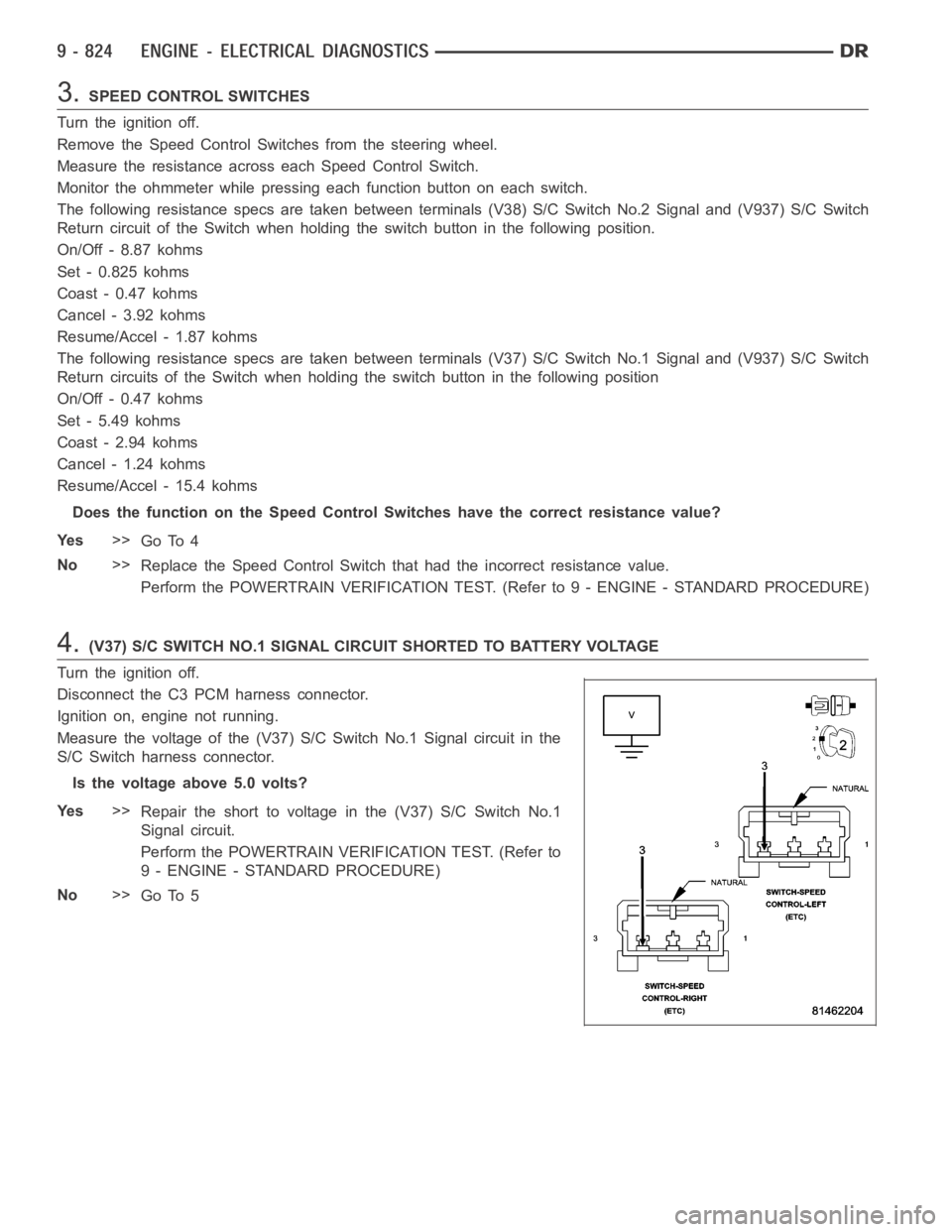
Measure the voltage of the (V37) S/C Switch No.1 Signal circuit in the
S/C Switch harness connector.
Is the voltage above 5.0 volts?
Ye s>>
Repair the short to voltage in the (V37) S/C Switch No.1
Signal circuit.
Perform the POWERTRAIN VERIFICATION TEST. (Refer to
9 - ENGINE - STANDARD PROCEDURE)
No>>
Go To 5
Page 141 of 5267
When Monitored:
Ignition on.
Set Condition:
S/C Switch No.1 is mechanically stuck in the On/Off, Resume/Accel, or Set position for too long. One trip fault.
Possible Causes
(V37) S/C SIGNAL CIRCUIT SHORTED TO BATTERY VOLTAGE
(V37) S/C SIGNAL CIRCUIT OPEN
(K900) SENSOR GROUND OPEN
(V37) S/C SIGNAL CIRCUIT SHORTED TO GROUND
(V37) S/C SIGNAL CIRCUIT SHORTED TO THE (K900) SENSOR GROUND
SPEED CONTROL SWITCH
PCM
Always perform the Pre-Diagnostic Troubleshooting procedure before proceeding. (Refer to 9 - ENGINE -
DIAGNOSIS AND TESTING).
Diagnostic Test
1.SPEED CONTROL SWITCH STATUS
Start the engine.
With a scan tool, monitor each which function for the Speed Control Switches.
Press and release each Speed Control Button.
- Resume/Accel
-Cancel
- Decel (Coast)
-On/Off
-Set
Does each switch function change status when pressing each switch?
Ye s>>
Refer to the INTERMITTENT CONDITION Diagnostic Procedure.
Perform the POWERTRAIN VERIFICATION TEST. (Refer to 9 - ENGINE - STANDARD PROCEDURE)
No>>
Go To 2
2.SPEED CONTROL SWITCHES
Turn the ignition off.
Disconnect and remove the Speed Control Switches from the steering wheel per Service Information.
Measure the resistance across each Speed Control Switch.
Monitor the ohmmeter while pressing each function button on each switch.
Resume/Accel - 15.4 kohms
Cancel - 1.24 kohms
Coast - 2.94 kohms
On/Off -0.47 kohms
Set - 5.49 kohms
Does the function on the Speed Control Switches have the correct resistance value?
Ye s>>
Go To 3
No>>
Replace the Speed Control Switch that had the incorrect resistance value.
Perform the POWERTRAIN VERIFICATION TEST. (Refer to 9 - ENGINE - STANDARD PROCEDURE)
Page 749 of 5267
P0633-SKIM SECRET KEY NOT ENTERED
For a complete wiring diagramRefer to Section 8W.
When Monitored:
Whilethekeyison.
Set Condition:
TheSKIMsecretkeywasnotcalibratedintotheECM.
Possible Causes
IMPROPER IGNITION KEY IS BEING USED
SKIM DTC’S
SKIM NOT CALIBRATED PROPERLY
Always perform the Pre-Diagnostic Troubleshooting procedure before proceeding. (Refer to 9 - ENGINE -
DIAGNOSIS AND TESTING)
Diagnostic Test
1.SKIM DTC’S
With the scan tool, read SKIM DTCs.
Are any SKIM DTC’s present?
Ye s>>
Repair all SKIM DTC’s first.
Perform POWERTRAIN VERIFICATION TEST VER - 1 (DIESEL). (Refer to 8 - ELECTRICAL/ELEC-
TRONIC CONTROL MODULES/ENGINE CONTROL MODULE - DIAGNOSIS AND TESTING)
No>>
Go To 2
2.IMPROPER IGNITION KEY IS BEING USED
Verify that the proper ignition key is in the ignition lock on the steering column.
Are the proper keys being used?
Ye s>>
Go To 3
No>>
Use the proper key for the vehicle.
Perform POWERTRAIN VERIFICATION TEST VER - 1 (DIESEL). (Refer to 8 - ELECTRICAL/ELEC-
TRONIC CONTROL MODULES/ENGINE CONTROL MODULE - DIAGNOSIS AND TESTING)
3.SKIM NOT CALIBRATED PROPERLY
Using the scan tool, recalibrate the ECM with the proper SKIM secret key.
With the scan tool, erase DTCs.
Cycle the ignition switch from on to off to on.
With the scan tool, read DTCs.
Did the DTC reset?
No>>
Te s t C o m p l e t e .
Ye s>>
Verify information is correct and replace ECM.
Perform POWERTRAIN VERIFICATION TEST VER - 1 (DIESEL). (Refer to 8 - ELECTRICAL/ELEC-
TRONIC CONTROL MODULES/ENGINE CONTROL MODULE - DIAGNOSIS AND TESTING)
Page 1497 of 5267
REMOVAL
1. Disconnect the battery negative cable.
2. Remove air cleaner assembly.
3. Remove radiator core support bracket.
4. Remove fan shroud with viscous fan assembly.
5. Remove drive belt.
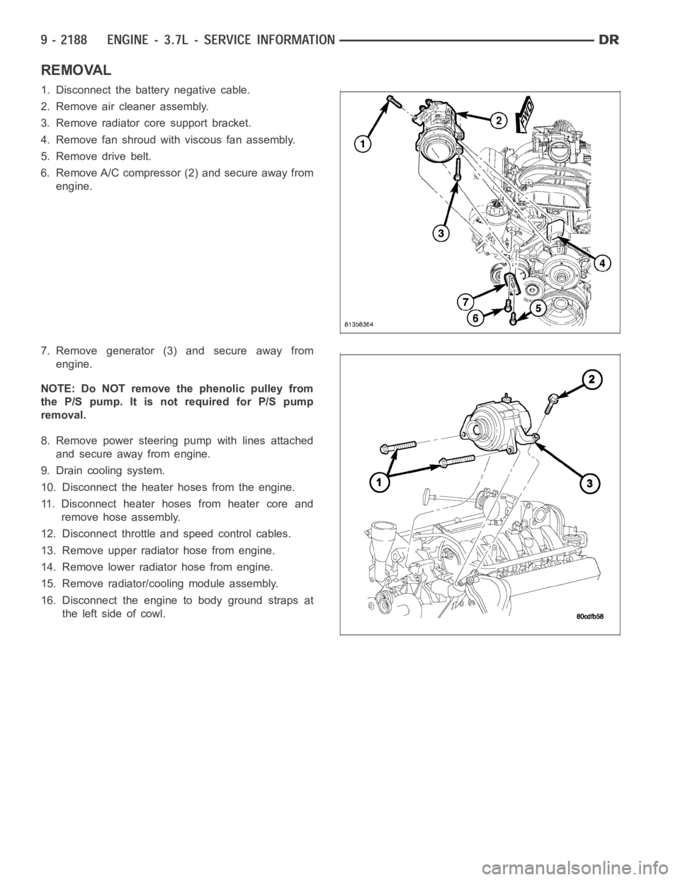
6. Remove A/C compressor (2) and secure away from
engine.
7. Remove generator (3) and secure away from
engine.
NOTE: Do NOT remove the phenolic pulley from
the P/S pump. It is not required for P/S pump
removal.
8. Remove power steering pump with lines attached
and secure away from engine.
9. Drain cooling system.
10. Disconnect the heater hoses from the engine.
11. Disconnect heater hoses from heater core and
remove hose assembly.
12. Disconnect throttle and speed control cables.
13. Remove upper radiator hose from engine.
14. Remove lower radiator hose from engine.
15. Remove radiator/cooling module assembly.
16. Disconnect the engine to body ground straps at
theleftsideofcowl.
Page 1503 of 5267
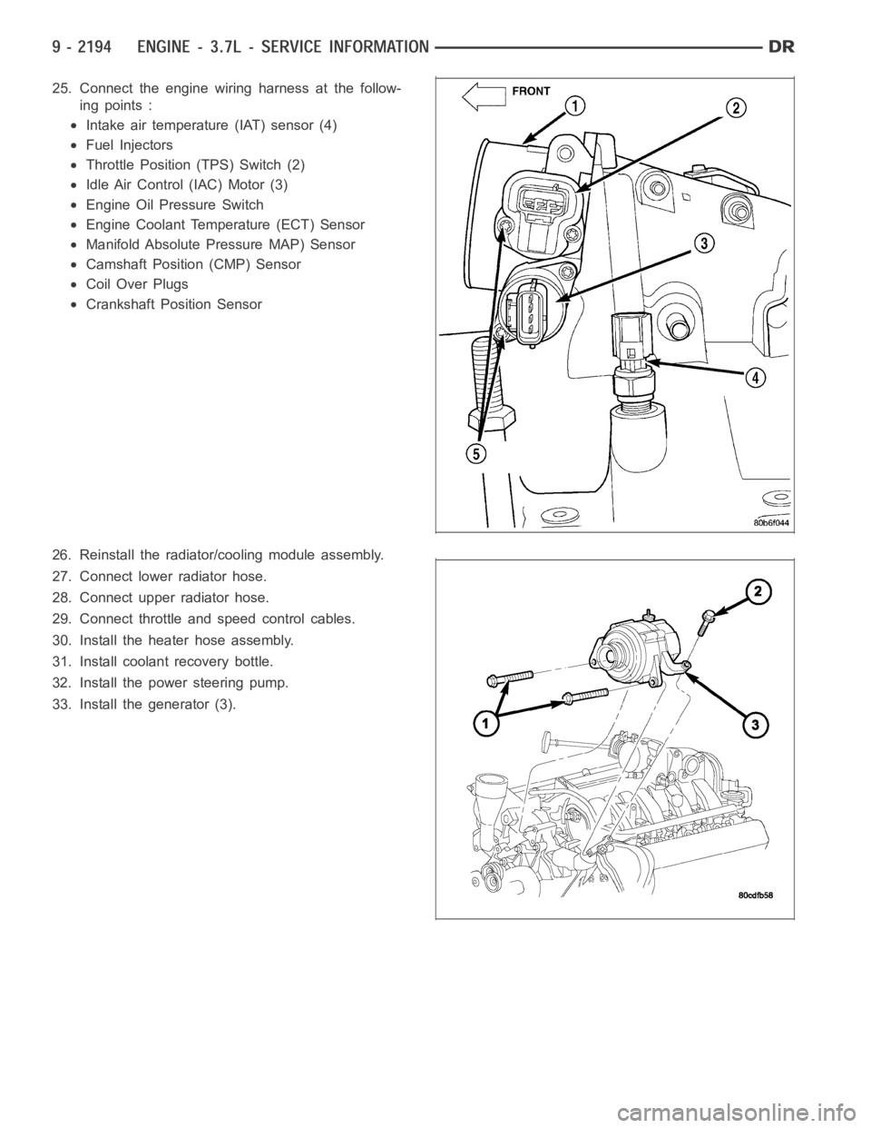
25. Connect the engine wiring harness at the follow-
ing points :
Intake air temperature (IAT) sensor (4)
Fuel Injectors
Throttle Position (TPS) Switch (2)
Idle Air Control (IAC) Motor (3)
Engine Oil Pressure Switch
Engine Coolant Temperature (ECT) Sensor
Manifold Absolute Pressure MAP) Sensor
Camshaft Position (CMP) Sensor
Coil Over Plugs
Crankshaft Position Sensor
26. Reinstall the radiator/cooling module assembly.
27. Connect lower radiator hose.
28. Connect upper radiator hose.
29. Connect throttle and speed control cables.
30. Install the heater hose assembly.
31. Install coolant recovery bottle.
32. Install the power steering pump.
33. Install the generator (3).
Page 1518 of 5267
7. Remove the master cylinder and booster assembly (Refer to 5 - BRAKES/HYDRAULIC/MECHANICAL/POWER
BRAKE BOOSTER - REMOVAL).
8. Remove the cylinder head cover (Refer to 9 - ENGINE/CYLINDER HEAD/CYLINDER HEAD COVER(S) -
REMOVAL).
9. Remove the fan shroud and fan blade assembly
(Refer to 7 - COOLING/ENGINE/RADIATOR FAN -
REMOVAL).
10. Remove accessory drive belt (Refer to 7 - COOL-
ING/ACCESSORY DRIVE/DRIVE BELTS -
REMOVAL).
11. Remove the power steering pump and set aside.
12. Rotate the crankshaft until the damper timing
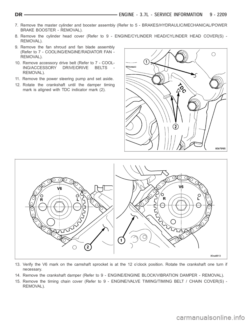
mark is aligned with TDC indicator mark (2).
13. Verify the V6 mark on the camshaft sprocket is at the 12 o’clock position. Rotate the crankshaft one turn if
necessary.
14. Remove the crankshaft damper (Refer to 9 - ENGINE/ENGINE BLOCK/VIBRATION DAMPER - REMOVAL).
15. Remove the timing chain cover (Refer to 9 - ENGINE/VALVE TIMING/TIMINGBELT / CHAIN COVER(S) -
REMOVAL).
Page 1521 of 5267
2. Position the new cylinder head gasket on the locat-
ing dowels.
CAUTION: When installing cylinder head, use care
not damage the tensioner arm or the guide arm.
3. Position the cylinder head onto the cylinder block.
Make sure the cylinder head seats fully over the
locating dowels.
NOTE: The four smaller cylinder head mounting
bolts require sealant to be added to them before
installing. Failure to do so may cause leaks.
4. Lubricate the cylinder head bolt threads with clean
engine oil and install the eight M11 bolts.
5. Coat the four M8 cylinder head bolts withMopar
Lock and Seal Adhesivethen install the bolts.
NOTE: The cylinder head bolts are tightened using
an angle torque procedure, however, the bolts are
not a torque-to-yield design.
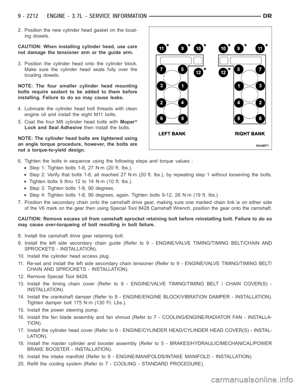
6. Tighten the bolts in sequence using the following steps and torque values:
Step 1: Tighten bolts 1-8, 27 Nꞏm (20 ft. lbs.).
Step 2: Verify that bolts 1-8, all reached 27 Nꞏm (20 ft. lbs.), by repeatingstep 1 without loosening the bolts.
Tightenbolts9thru12to14Nꞏm(10ft.lbs.).
Step 3: Tighten bolts 1-8, 90 degrees.
Step 4: Tighten bolts 1-8, 90 degrees, again. Tighten bolts 9-12, 26 Nꞏm (19ft. lbs.)
7. Position the secondary chain onto the camshaft drive gear, making sure one marked chain link is on either side
of the V6 mark on the gear then using Special Tool 8428 Camshaft Wrench, position the gear onto the camshaft.
CAUTION: Remove excess oil from camshaft sprocket retaining bolt before reinstalling bolt. Failure to do so
may cause over-torqueing of bolt resulting in bolt failure.
8. Install the camshaft drive gear retaining bolt.
9. Install the left side secondary chain guide (Refer to 9 - ENGINE/VALVE TIMING/TIMING BELT/CHAIN AND
SPROCKETS - INSTALLATION).
10. Install the cylinder head access plug.
11. Re-set and install the left side secondary chain tensioner (Refer to 9 -ENGINE/VALVE TIMING/TIMING BELT/
CHAIN AND SPROCKETS - INSTALLATION).
12. Remove Special Tool 8429.
13. Install the timing chain cover (Refer to 9 - ENGINE/VALVE TIMING/TIMING BELT / CHAIN COVER(S) -
INSTALLATION).
14. Install the crankshaft damper (Refer to 9 - ENGINE/ENGINE BLOCK/VIBRATION DAMPER - INSTALLATION).
Tighten damper bolt 175 Nꞏm (130 Ft. Lbs.).
15. Install the power steering pump.
16. Install the fan blade assembly and fan shroud (Refer to 7 - COOLING/ENGINE/RADIATOR FAN - INSTALLA-
TION).
17. Install the cylinder head cover (Refer to 9 - ENGINE/CYLINDER HEAD/CYLINDER HEAD COVER(S) - INSTAL-
LATION).
18. Install the master cylinder and booster assembly (Refer to 5 - BRAKES/HYDRAULIC/MECHANICAL/POWER
BRAKE BOOSTER - INSTALLATION).
19. Install the intake manifold (Refer to 9 - ENGINE/MANIFOLDS/INTAKE MANIFOLD - INSTALLATION).
20. Refill the cooling system (Refer to 7 - COOLING - STANDARD PROCEDURE).
Page 1617 of 5267
6. Remove power steering pump (Refer to 19 -
STEERING/PUMP - REMOVAL).
7. Remove access plug from left and right cylinder
heads for access to chain guide fasteners.
8. Remove the oil fill housing to gain access to the
right side tensioner arm fastener.
9. Remove crankshaft damper (Refer to 9 - ENGINE/
ENGINE BLOCK/VIBRATION DAMPER -
REMOVAL) and timing chain cover (Refer to 9 -
ENGINE/VALVE TIMING/TIMING BELT / CHAIN
COVER(S) - REMOVAL).
10. Collapse and pin primary chain tensioner.
CAUTION: Plate behind left secondary chain ten-
sioner could fall into oil pan. Therefore, cover pan
opening.
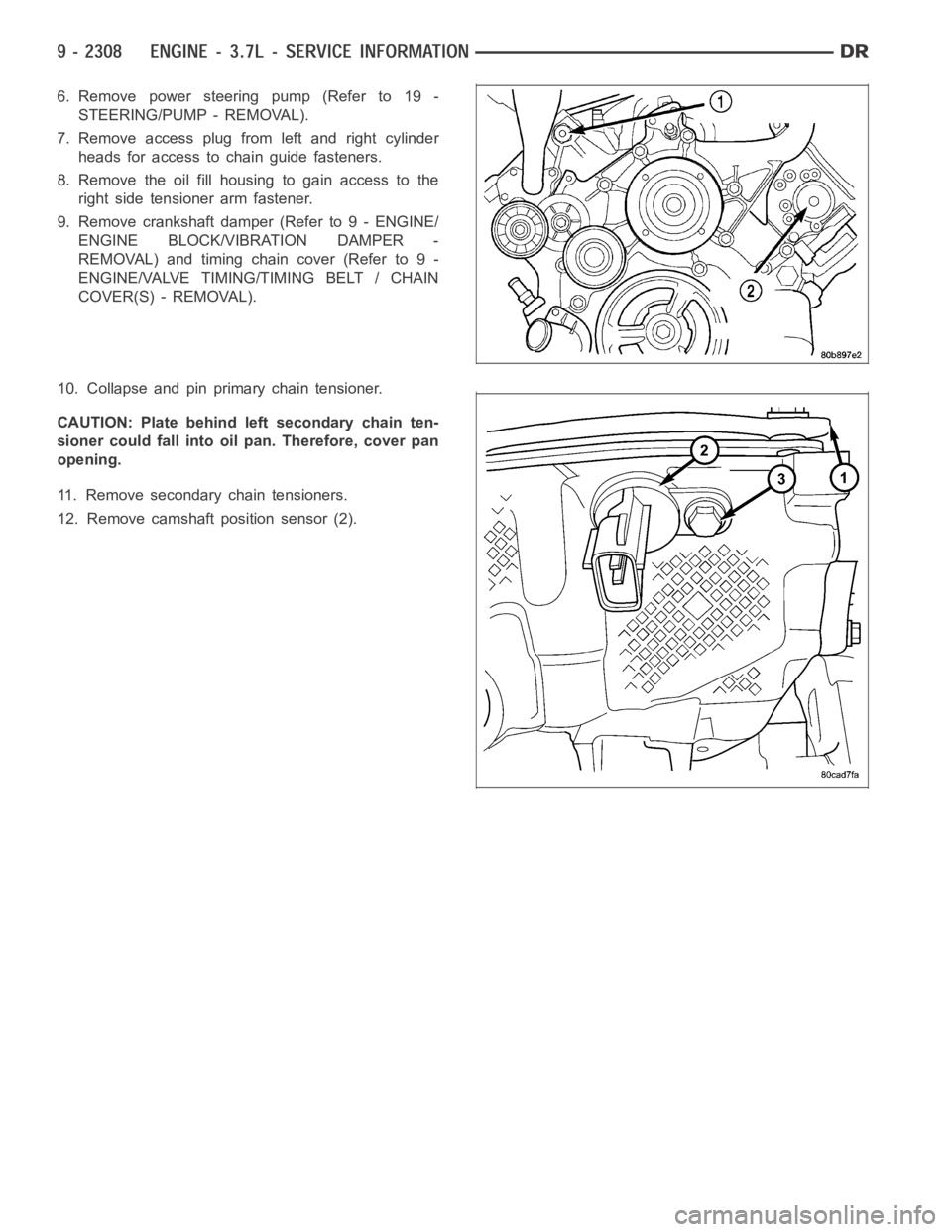
11. Remove secondary chain tensioners.
12. Remove camshaft position sensor (2).