2006 DODGE RAM SRT-10 check oil
[x] Cancel search: check oilPage 39 of 5267

3.(K342) ASD CONTROL OUTPUT CIRCUIT SHORTED TO GROUND
Turn the ignition off
Disconnect the C10 TIPM harness connector.
Measure resistance between ground and (K342) ASD Control Output
circuit at the C10 TIPM harness connector.
Istheresistancebelow100ohms?
Ye s>>
Go To 4
No>>
Go To 7
4.(K342) ASD CONTROL OUTPUT CIRCUIT SHORTED TO GROUND AT THE FUEL INJECTORS
While checking for a short to ground at C10 TIPM harness connector,
disconnect the Fuel Injector harness connectors one at a time.
Does the resistance change to above 100 ohms when any of
the Fuel Injector harness connectors are disconnected?
Ye s>>
Replace the Fuel Injector that causes the resistance to
increase above 100 ohms when disconnected.
Perform the POWERTRAIN VERIFICATION TEST. (Refer to
9 - ENGINE - STANDARD PROCEDURE)
No>>
Go To 5
5.(K342) ASD CONTROL OUTPUT CIRCUIT SHORTED TO GROUND AT THE IGNITION COILS
While checking for a short to ground at C10 TIPM harness connector,
disconnect the Ignition Coil harness connectors one at a time.
Does the resistance change to above 100 ohms when any of
the Ignition Coil harness connectors are disconnected?
Ye s>>
Replace the Coil that causes the resistance to increase
above 100 ohms when disconnected.
Perform the POWERTRAIN VERIFICATION TEST. (Refer to
9 - ENGINE - STANDARD PROCEDURE)
No>>
Go To 6
Page 43 of 5267

3.(K342) ASD CONTROL OUTPUT CIRCUIT SHORTED TO VOLTAGE
Turn the ignition off
Disconnect the C10 TIPM harness connector.
Measure the voltage on the (K342) ASD Control Output circuit at the
C10 TIPM harness connector.
Is the voltage above 10 volts?
Ye s>>
Go To 4
No>>
Go To 7
4.(K342) ASD CONTROL OUTPUT CIRCUIT SHORTED TO VOLTAGE AT THE FUEL INJECTORS
While checking for a short to voltage at C10 TIPM harness connector,
disconnect the Fuel Injector harness connectors one at a time.
Does the voltage change to below 10 volts when any of the
Fuel Injector harness connectors are disconnected?
Ye s>>
Replace the Fuel Injector that causes the voltage to
decrease below 10 volts when disconnected.
Perform the POWERTRAIN VERIFICATION TEST. (Refer to
9 - ENGINE - STANDARD PROCEDURE)
No>>
Go To 5
5.(K342) ASD CONTROL OUTPUT CIRCUIT SHORTED TO VOLTAGE AT THE IGNITION COILS
While checking for a short to voltage at C10 TIPM harness connector,
disconnect the Ignition Coil harness connectors one at a time.
Does the voltage change to below 10 volts when any of the
Ignition Coil harness connectors are disconnected?
Ye s>>
Replace the Coil that causes the voltage to decrease below
10 volts when disconnected.
Perform the POWERTRAIN VERIFICATION TEST. (Refer to
9 - ENGINE - STANDARD PROCEDURE)
No>>
Go To 6
Page 52 of 5267
6.PCM Turn the ignition off.
Disconnect C3 NGC harness connector.
CAUTION: Do not probe the PCM harness connectors. Probing the PCM harness connectors will damage
the PCM terminals resulting in poor terminal to pin connection. Install Miller Special Tool #8815 and #8815-1
to perform diagnosis.
With a voltmeter, use Negative lead of the voltmeter along with terminal probe tool #6801, probe the (K342) ASD
Control Output circuit at the appropriate terminals of special tool #8815.
With the Positive lead of the voltmeter along with terminal probe tool #6801, back probe the (K342) ASD Control
Output circuit at the C10 TIPM harness connector.
Start the engine and allow it to idle.
WARNING: When the engine is operating, do not stand in direct line with the fan. Do not put your hands
near the pulleys, belts, or fan. Do notwear loose clothing. Failure to follow these instructions can result in
personal injury or death.
Measure the voltage of the (K342) ASD Control Output circuit.
Is the voltage above 0.001 of a volt (1.0mV) for any of the Ignition Coil ASD Control Output circuits?
Ye s>>
Repair the excessive resistance in the (K342) ASD Control Output circuit tothePCM.
Perform the POWERTRAIN VERIFICATION TEST. (Refer to 9 - ENGINE - STANDARD PROCEDURE)
No>>
Replace and program the Powertrain Control Module in accordance with Service Information.
Perform the POWERTRAIN VERIFICATION TEST. (Refer to 9 - ENGINE - STANDARD PROCEDURE)
7.TOTALLY INTEGRATED POWER MODULE
NOTE: Before continuing, check the TIPM harness connector terminals for corrosion, damage, or terminal
push out. Repair as necessary.
Using the schematics as a guide, inspect the wire harness and connectors.
Pay particular attention to allPower and voltage circuits.
Were any problems found?
Ye s>>
Repair as necessary.
Perform the POWERTRAIN VERIFICATION TEST. (Refer to 9 - ENGINE - STANDARD PROCEDURE)
No>>
Replace the Totally Integrated Power Module per Service Information.
Perform the POWERTRAIN VERIFICATION TEST. (Refer to 9 - ENGINE - STANDARD PROCEDURE)
Page 101 of 5267
6.PCM
NOTE: Before continuing, check the PCM harness connector terminals for corrosion, damage, or terminal
push out. Repair as necessary.
Using the schematics as a guide, inspect the wire harness and connectors. Pay particular attention to all Power and
Ground circuits.
Were there any problems found?
Ye s>>
Repair as necessary.
Perform the POWERTRAIN VERIFICATION TEST. (Refer to 9 - ENGINE - STANDARD PROCEDURE)
No>>
Replace and program the Powertrain Control Module per Service Information.
Perform the POWERTRAIN VERIFICATION TEST. (Refer to 9 - ENGINE - STANDARD PROCEDURE)
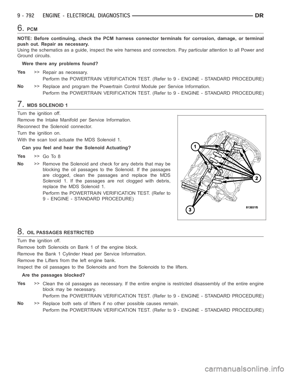
7.MDS SOLENOID 1
Turn the ignition off.
Remove the Intake Manifold per Service Information.
Reconnect the Solenoid connector.
Turn the ignition on.
With the scan tool actuate the MDS Solenoid 1.
Can you feel and hear the Solenoid Actuating?
Ye s>>
Go To 8
No>>
Remove the Solenoid and check for any debris that may be
blocking the oil passages to the Solenoid. If the passages
are clogged, clean the passages and replace the MDS
Solenoid 1. If the passages are not clogged with debris,
replace the MDS Solenoid 1.
Perform the POWERTRAIN VERIFICATION TEST. (Refer to
9 - ENGINE - STANDARD PROCEDURE)
8.OIL PASSAGES RESTRICTED
Turn the ignition off.
Remove both Solenoids on Bank 1 of the engine block.
Remove the Bank 1 Cylinder Head per Service Information.
Remove the Lifters from the left engine bank.
Inspect the oil passages to the Solenoids and from the Solenoids to the lifters.
Are the passages blocked?
Ye s>>
Clean the oil passages as necessary. If the entire engine is restricted disassembly of the entire engine
block may be necessary.
Perform the POWERTRAIN VERIFICATION TEST. (Refer to 9 - ENGINE - STANDARD PROCEDURE)
No>>
Replace both sets of lifters if no other possible causes remain.
Perform the POWERTRAIN VERIFICATION TEST. (Refer to 9 - ENGINE - STANDARD PROCEDURE)
Page 106 of 5267
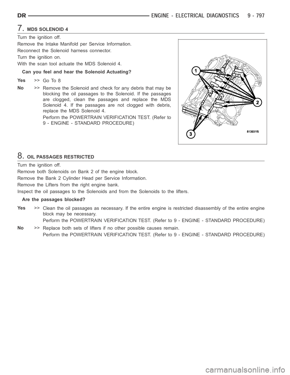
7.MDS SOLENOID 4
Turn the ignition off.
Remove the Intake Manifold per Service Information.
Reconnect the Solenoid harness connector.
Turn the ignition on.
With the scan tool actuate the MDS Solenoid 4.
Can you feel and hear the Solenoid Actuating?
Ye s>>
Go To 8
No>>
Remove the Solenoid and check for any debris that may be
blocking the oil passages to the Solenoid. If the passages
are clogged, clean the passages and replace the MDS
Solenoid 4. If the passages are not clogged with debris,
replace the MDS Solenoid 4.
Perform the POWERTRAIN VERIFICATION TEST. (Refer to
9 - ENGINE - STANDARD PROCEDURE)
8.OIL PASSAGES RESTRICTED
Turn the ignition off.
Remove both Solenoids on Bank 2 of the engine block.
Remove the Bank 2 Cylinder Head per Service Information.
Remove the Lifters from the right engine bank.
Inspect the oil passages to the Solenoids and from the Solenoids to the lifters.
Are the passages blocked?
Ye s>>
Clean the oil passages as necessary. If the entire engine is restricted disassembly of the entire engine
block may be necessary.
Perform the POWERTRAIN VERIFICATION TEST. (Refer to 9 - ENGINE - STANDARD PROCEDURE)
No>>
Replace both sets of lifters if no other possible causes remain.
Perform the POWERTRAIN VERIFICATION TEST. (Refer to 9 - ENGINE - STANDARD PROCEDURE)
Page 111 of 5267
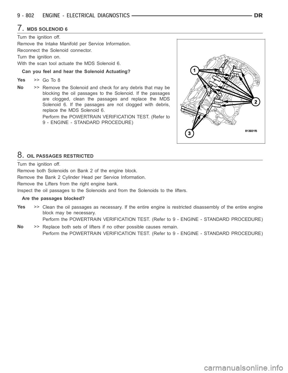
7.MDS SOLENOID 6
Turn the ignition off.
Remove the Intake Manifold per Service Information.
Reconnect the Solenoid connector.
Turn the ignition on.
With the scan tool actuate the MDS Solenoid 6.
Can you feel and hear the Solenoid Actuating?
Ye s>>
Go To 8
No>>
Remove the Solenoid and check for any debris that may be
blocking the oil passages to the Solenoid. If the passages
are clogged, clean the passages and replace the MDS
Solenoid 6. If the passages are not clogged with debris,
replace the MDS Solenoid 6.
Perform the POWERTRAIN VERIFICATION TEST. (Refer to
9 - ENGINE - STANDARD PROCEDURE)
8.OIL PASSAGES RESTRICTED
Turn the ignition off.
Remove both Solenoids on Bank 2 of the engine block.
Remove the Bank 2 Cylinder Head per Service Information.
Remove the Lifters from the right engine bank.
Inspect the oil passages to the Solenoids and from the Solenoids to the lifters.
Are the passages blocked?
Ye s>>
Clean the oil passages as necessary. If the entire engine is restricted disassembly of the entire engine
block may be necessary.
Perform the POWERTRAIN VERIFICATION TEST. (Refer to 9 - ENGINE - STANDARD PROCEDURE)
No>>
Replace both sets of lifters if no other possible causes remain.
Perform the POWERTRAIN VERIFICATION TEST. (Refer to 9 - ENGINE - STANDARD PROCEDURE)
Page 116 of 5267
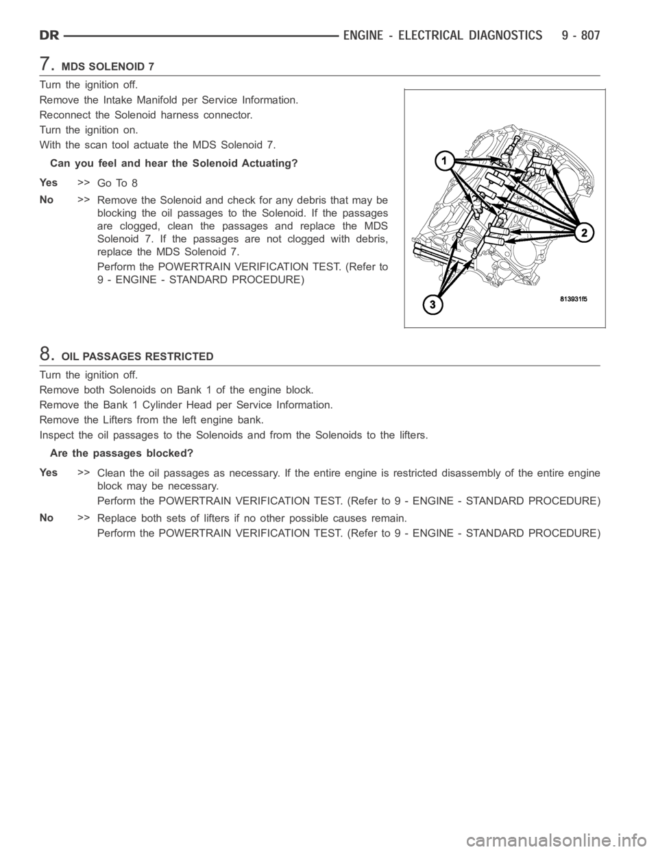
7.MDS SOLENOID 7
Turn the ignition off.
Remove the Intake Manifold per Service Information.
Reconnect the Solenoid harness connector.
Turn the ignition on.
With the scan tool actuate the MDS Solenoid 7.
Can you feel and hear the Solenoid Actuating?
Ye s>>
Go To 8
No>>
Remove the Solenoid and check for any debris that may be
blocking the oil passages to the Solenoid. If the passages
are clogged, clean the passages and replace the MDS
Solenoid 7. If the passages are not clogged with debris,
replace the MDS Solenoid 7.
Perform the POWERTRAIN VERIFICATION TEST. (Refer to
9 - ENGINE - STANDARD PROCEDURE)
8.OIL PASSAGES RESTRICTED
Turn the ignition off.
Remove both Solenoids on Bank 1 of the engine block.
Remove the Bank 1 Cylinder Head per Service Information.
Remove the Lifters from the left engine bank.
Inspect the oil passages to the Solenoids and from the Solenoids to the lifters.
Are the passages blocked?
Ye s>>
Clean the oil passages as necessary. If the entire engine is restricted disassembly of the entire engine
block may be necessary.
Perform the POWERTRAIN VERIFICATION TEST. (Refer to 9 - ENGINE - STANDARD PROCEDURE)
No>>
Replace both sets of lifters if no other possible causes remain.
Perform the POWERTRAIN VERIFICATION TEST. (Refer to 9 - ENGINE - STANDARD PROCEDURE)
Page 123 of 5267

P1521–INCORRECT ENGINE OIL TYPE
When Monitored:
Engine Running.
Set Condition:
Using the oil pressure, oil temperature and other vital engine inputs the PCM can determine the engine oil
viscosity. Incorrect viscosity will effect the operation of the MDS by delaying cylinder activation.
Possible Causes
INCORRECT ENGINE OIL TYPE
ENGINE OIL CONTAMINATION
ENGINE OIL
Always perform the Pre-Diagnostic Troubleshooting procedure before proceeding. (Refer to 9 - ENGINE -
DIAGNOSIS AND TESTING).
Diagnostic Test
1.ACTIVE DTC
NOTE: Review the customers oil change history. Make sure the customers is using the correct engine oil
viscosity. If the incorrect oil is being used, change the oil, using the correct engine oil viscosity.
Ignition on, engine off.
With the scan tool, read DTCs.
Is the DTC active at this time?
Ye s>>
Go to 2
No>>
Te s t C o m p l e t e .
2.ENGINE OIL
NOTE: If any engine oil pressure or oil temperature DTCs set along with P1521, repair them before continu-
ing with the P1521 diagnostics.
The following conditions must be checked.
OEM recommended oil viscosity is being used.
Customer is following the oil change schedule.
Check the engine oil for contamination. (i.e., fuel and/or engine coolant)
Internal engine condition that may effect oil pressure.
Were any of the above condition found?
Ye s>>
Repair as necessary.
Perform the POWERTRAIN VERIFICATION TEST. (Refer to 9 - ENGINE - STANDARD PROCEDURE)
No>>
Change the engine oil using the correct oil viscosity.
Perform the POWERTRAIN VERIFICATION TEST. (Refer to 9 - ENGINE - STANDARD PROCEDURE)