2006 DODGE RAM SRT-10 service indicator
[x] Cancel search: service indicatorPage 452 of 5267
23. If thelift foot setsare continually used, a speed control overshoot/undershoot condition will develop.
24. To
unlearnthe overshoot/undershoot condition, the vehicle operator has to press and release the set button
while maintaining the desired set speedusing the accelerator pedal (not decelerating or accelerating).
25. Then turn the cruise control switch to the OFF position (or press the CANCEL button if equipped) after waiting
10 seconds.
26. This procedure must be performed approximately 10-15 times to completely unlearn the overshoot/undershoot
condition.
Did the Speed Control pass the above test?
Ye s>>
Repair is complete.
No>>
Check for any related Technical Service Bulletins and/or refer to the appropriate Diagnostic Procedure.
3.POWERTRAIN VERIFICATION TEST 2
1. If this vehicle is equipped with an Electronic Throttle Control system,and the APP Sensors, PCM, or Throttle
Body Assembly has been replaced use a scan tool to perform the ETC RELEARN function.
NOTE: 2. After completing the Powertrain Verification Test the Transmission Verification Test must be per-
formed.
NOTE: 3. If the PCM has been replaced and the correct VIN and mileage have notbeen programmed, a DTC
will set in the ABS Module, Airbag Module and the SKIM/SKREEM.
NOTE: 4. If the vehicle is equipped with a Sentry Key Remote Entry, Secret Key data must be updated. Refer
to the Service Information for the PCM, SKIM/SKREEM and the Transponder (ignition key) for programming
information. Using the scan tool, program the Secret Key information intothe PCM using the PCM replaced
function under the WCM menu.
5. Inspect the vehicle to make sure that all components related to the repair are properly installed and connected.
6. With the scan tool, clear DTCs.
7. Perform generator output test. Refer to the appropriate service information as necessary.
8. Start the engine and set engine speed to 2000 RPM for at least thirty seconds.
9. Cycle the ignition key off and on.
10. With the scan tool, read the DTCs.
Are any DTCs or symptoms remaining?
Ye s>>
Check for any Technical Service Bulletins and/or refer to the appropriateDiagnostic Procedure.
No>>
Repair is complete.
4.POWERTRAIN VERIFICATION TEST 3
1. Install the Miller Tool #8404 Evaporative Emission Leak Detector (EELD) according to the instructions in the pre-
vious DTC table.
2. Set the smoke/air control switch to AIR.
3. Insert the tester’s AIR supply tip (clear hose) into the appropriate calibration orifice on the tester’s control panel
(based on DTC leak size).
4. Press the remote smoke/air start button.
5. Position the red flag on the air flow meter so it is aligned with the indicator ball.
6. When the calibration is complete, release the remote button. The EELD flow meter is now calibrated in liters per
minute to the size of leak indicated by the DTC set in the PCM.
7. Install the service port adapter #8404-14 on the vehicle’s service port.
8. Connect the Air supply hose from the EELD to the vehicle.
9. Press the remote button to activate AIR flow.
NOTE: 10. Larger volume fuel tanks, lower fuel levels or if the vehicle is equipped with a Flow Management
Valve may indicate high flow and will require 4 to 5 minutes to fill.
11. Compare the flow meter indicator ball reading to the red flag.
12. ABOVE the red flag indicates a leak present.
13. BELOW the red flag indicates a sealed system.
Page 453 of 5267
NOTE: If this vehicle is equipped with an Electronic Throttle Control system, and the APP Sensors, PCM, or
Throttle Body Assembly have been replaced, use the scan tool to perform theETC RELEARN function.
14. If the indicator ball shows a leak present, perform the smoke test indicated in the previous test and identify the
leak and repair. Perform this verification test when the repair is complete.
Didtheindicatorballindicatethealeakispresent?
Ye s>>
Repeat the DTC test to identify the leak and repair.
No>>
Repair is complete.
5.POWERTRAIN VERIFICATION TEST 4
NOTE: 1. After completing the Powertrain Verification Test the Transmission Verification Test must be per-
formed.
NOTE: 2. If the PCM has been replaced and the correct VIN and mileage have notbeen programmed, a DTC
will set in the ABS Module, Airbag Module and the SKIM/SKREEM.
NOTE: 3. If the vehicle is equipped with a Sentry Key Remote Entry, Secret Key data must be updated. Refer
to the Service Information for the PCM, SKIM/SKREEM and the Transponder (ignition key) for programming
information. Using the scan tool, program the Secret Key information intothe PCM using the PCM replaced
function under the WCM menu.
NOTE: 4. If this vehicle is equipped with an Electronic Throttle Control system, and the APP Sensors, PCM,
or Throttle Body Assembly have been replaced, use the scan tool to perform the ETC RELEARN function.
NOTE: 5. When replacing an O2 Sensor, the PCM RAM memory must be cleared, either by disconnecting the
PCM C1 connector or momentarily disconnecting the Battery negative terminal.
6. The NGC learns the characteristics of each O2 heater element and these old values should be cleared when
installing a new O2 sensor. The customermay experience driveability issues if this is not performed.
7. Inspect the vehicle to make sure that all engine components are properlyinstalled and connected. Reassemble
and reconnect components as necessary.
8. Connect the scan tool to the data link connector.
9. Make sure the fuel tank has at least a quarter tank of fuel. Turn off all accessories.
10. If the Catalyst was replaced, with the scan tool go to the MiscellaneousMenu Option
Catalyst Replacedand
press enter.
11. If a Comprehensive Component DTC was repaired, perform steps 12 - 14. Ifa Major OBDII Monitor DTC was
repaired skip those steps and continue verification.
12. After the ignition has been off for at least 10 seconds, restart the vehicle and run 2 minutes.
13. With the scan tool, monitor the appropriate pre-test enabling conditions until all conditions have been met. Once
the conditions have been met, switch screen to the appropriate OBDII monitor, (Audible beeps when the monitor is
running).
14. If the repaired OBDII trouble code has reset or was seen in the monitor while on the road test, the repair is not
complete. Check for any related technical service bulletins or flash updates and return to Engine Electrical Diag-
nostic List.
15. If the conditions cannot be duplicated, erase all DTCs with the Scan tool.
16. If another DTC has set, return to the Engine Electrical Diagnostic Listand follow the path specified for that DTC.
Did the OBDII Monitor run successfully and has the Good Trip Counter changed to one or more?
Ye s>>
Repair is complete.
No>>
Check for any related Technical Service Bulletins and/or refer to the appropriate Diagnostic Procedure.
Page 468 of 5267

When Monitored:
While Engine is running.
Set Condition:
When the engine speed detected by the Engine Position Sensor (cam) and the Engine Speed Sensor (crank)
differ by a specified RPM amount.
Possible Causes
DAMAGE TO THE ESS OR EPS
MECHANICAL MISALIGNMENT OF THE ESS OR EPS
MECHANICAL MISALIGNMENT OF THE CAMSHAFT AND CRANKSHAFT GEARS
INTERMITTENT CONDITION
Diagnostic Test
1.DAMAGE TO THE ESS OR EPS
Visually inspect the condition of the tone wheel, ESS, and EPS for damage.
Are any of the components damaged?
Ye s>>
Repair or replace any damaged component.
Perform POWERTRAIN VERIFICATION TEST VER - 1 (DIESEL). (Refer to 9 - ENGINE- DIAGNOSIS
AND TESTING)
No>>
Go To 2
2.MECHANICAL MISALIGNMENT OF THE ESS OR EPS
Verify the speed indicator ring is properly positioned relative to the locating pin in the front face of the crankshaft.
Is the speed indicator ring properly installed?
Ye s>>
Go To 3
No>>
Repair the speed ring indicator ring installation.
Perform POWERTRAIN VERIFICATION TEST VER - 1 (DIESEL). (Refer to 9 - ENGINE- DIAGNOSIS
AND TESTING)
3.MECHANICAL MISALIGNMENT OF THE CAMSHAFT AND CRANKSHAFT GEARS
Check the mechanical alignment of the camshaft gear to the crankshaft gear. Refer to service manual for assis-
tance.
Are the gear teeth in proper alignment?
Ye s>>
Refer to the INTERMITTENT CONDITION Symptom (Diagnostic Procedure). (Refer to 9 - ENGINE -
DIAGNOSIS AND TESTING)
No>>
Repair the gear alignment.
Perform POWERTRAIN VERIFICATION TEST VER - 1 (DIESEL). (Refer to 9 - ENGINE- DIAGNOSIS
AND TESTING)
Page 1273 of 5267
3.VISUAL AND PHYSICAL INSPECTION
Perform a visual and physical inspection of the entire Evaporative Emission system.
Check for the follow conditions:
- Holes or cracks
- Loose seal points
- Evidence of damaged components
- Incorrect routing of hoses and tubes
- Fuel Cap gasket seal
Were any of the above conditions found?
Ye s>>
Repair as necessary.
Perform the POWERTRAIN VERIFICATION TEST. (Refer to 9 - ENGINE - STANDARD PROCEDURE)
No>>
Go To 4
4.VERIFY EVAPORATIVE EMISSION LEAK
To continue testing you will need Miller Tool #8404A Evaporative EmissionLeak Detector (EELD).
WARNING: Keep lit cigarettes, sparks, flames, and other ignition sourcesaway from the test area to prevent
the ignition of explosive gases. Keep the test area well ventilated.
NOTE: The fuel tank should have between 20% and 80% of fuel tank capacity to properly test the Evap
system.
Connect the red power lead of the EELD to the battery positive terminal and the black ground lead to battery neg-
ative terminal.
Block the vent hose of the canister if using the service port.
Connect shop air to the EELD.
Set the smoke/air control switch to AIR.
Insert the tester’s AIR supply tip (clear hose) into the appropriate calibration orifice on the tester’s control panel
(based on DTC leak size).
Press the remote smoke/air start button.
Position the red flag on the air flow meter so it is aligned with the indicatorball.
When the calibration is complete, release the remote button. The EELD flowmeter is now calibrated in liters per
minute to the size leak indicated by the DTC set in the PCM.
Install the service port adapter #8404-14 on the vehicle’s service port and block the vent hose of the EVAP Canister
(if equipped) or install the #8404-ADP service adaptor into the filter line.
Connect the Air supply hose from the EELD to the service port (if equipped) or to the #8404-ADP adapter.
Press the remote button to activate AIR flow.
NOTE: Larger volume fuel tanks, lower fuel levels or if the vehicle is equipped with a Flow Management
Valve may indicate high flow and will require 4 to 5 minutes to fill.
Compare the flow meter indicator ball reading to the red flag.
ABOVE the red flag indicates a leak present.
BELOW the red flag indicates a sealed system.
Is the indicator ball above the red flag?
Ye s>>
Go To 5
No>>
Refer to the Freeze Frame data recorded in Step 1. If the data indicates thatthe vehicle was in motion
when the DTC was set, verify that all hoses are properly connected. Test Complete.
Page 1274 of 5267
5.EVAPORATIVE EMISSION LEAK DETECTION
NOTE: A thorough visual inspection of the Evap system hoses, tubes, and connections may save time in
your diagnosis. Look for any physical damage or signs of wetness at connections. The strong smell of fuel
vapors may also aid diagnosis.
To continue testing, you will need Miller Tool #8404A Evaporative Emissions Leak Detector (EELD).
Remove the Air supply hose from the service port (if equipped) or from the #8404-ADP adapter.
Connect the SMOKE supply tip (black hose) to the service port (if equipped)or to the #8404-ADP adapter.
Set the smoke/air control switch to SMOKE.
NOTE: The flow meter indicator ball will not move in the smoke mode.
Press the remote smoke/air start button.
NOTE: Make sure that smoke has filled the EVAP system by continuing to presstheremotesmoke/airstart
button, remove the vehicle fuel cap, and wait for the smoke to exit. Once smoke is indicated reinstall the
fuel cap.
NOTE: For optimal performance, introduce smoke into the system for an additional 60 seconds; continue
introducing smoke at 15 second intervals, as necessary.
While still holding the remote smoke/air start button, use the white light(#8404-CLL) to follow the EVAP system
path, and look for the source of the leak indicated by exiting smoke.
If a leak is concealed from view (i.e., top of fuel tank), release the remotesmoke/air start button, and use the ultra-
violet (UV) black light #8404-UVL and the yellow goggles 8404-20 to look for residual traces of dye that is left
behind by the smoke.
The exiting smoke deposits a residual fluid that is either bright green or bright yellow in color when viewed with a
UV light.
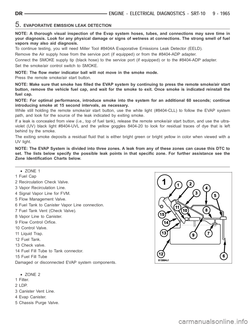
NOTE: The EVAP System is divided into three zones. A leak from any of these zonescancausethisDTCto
set. The lists below specify the possible leak points in that specific zone. For further assistance see the
Zone Identification Charts below.
ZONE 1
1FuelCap
2 Recirculation Check Valve.
3 Vapor Recirculation Line.
4 Signal Vapor Line for FVM.
5 Flow Management Valve.
6 Fuel Tank to Canister Vapor Line connection.
7 Fuel Tank Vent (Check Valve).
8 Vapor Line to Canister.
9 Flow Control Orfice.
10 Control Valve.
11 Liquid Trap.
12 Fuel Tank.
13 Check valve.
14 Fuel Fill Tube to Tank connector.
15 Fuel Fill Tube
Damaged or disconnected EVAP system components.
ZONE 2
1Filter.
2LDP.
3 Canister Vent Line.
4EvapCanister.
5 Chassis Purge Valve.
Page 1283 of 5267
3.VISUAL AND PHYSICAL INSPECTION
Perform a visual and physical inspection of the entire Evaporative Emission system.
Check for the follow conditions:
- Holes or cracks
- Loose seal points
- Evidence of damaged components
- Incorrect routing of hoses and tubes
- Fuel Cap gasket seal
Were any of the above conditions found?
Ye s>>
Repair as necessary.
Perform the POWERTRAIN VERIFICATION TEST. (Refer to 9 - ENGINE - STANDARD PROCEDURE)
No>>
Go To 4
4.VERIFY EVAPORATIVE EMISSION LEAK
To continue testing you will need Miller Tool #8404A Evaporative EmissionLeak Detector (EELD).
WARNING: Keep lit cigarettes, sparks, flames, and other ignition sourcesaway from the test area to prevent
the ignition of explosive gases. Keep the test area well ventilated.
NOTE: The fuel tank should have between 20% and 80% of fuel tank capacity to properly test the Evap
system.
Connect the red power lead of the EELD to the battery positive terminal and the black ground lead to battery neg-
ative terminal.
Block the vent hose of the canister if using the service port.
Connect shop air to the EELD.
Set the smoke/air control switch to AIR.
Insert the tester’s AIR supply tip (clear hose) into the appropriate calibration orifice on the tester’s control panel
(based on DTC leak size).
Press the remote smoke/air start button.
Position the red flag on the air flow meter so it is aligned with the indicatorball.
When the calibration is complete, release the remote button. The EELD flowmeter is now calibrated in liters per
minute to the size leak indicated by the DTC set in the PCM.
Install the service port adapter #8404-14 on the vehicle’s service port and block the vent hose of the EVAP Canister
(if equipped) or install the #8404-ADP service adaptor into the filter line.
Connect the Air supply hose from the EELD to the service port (if equipped) or to the #8404-ADP adapter.
Press the remote button to activate AIR flow.
NOTE: Larger volume fuel tanks, lower fuel levels or if the vehicle is equipped with a Flow Management
Valve may indicate high flow and will require 4 to 5 minutes to fill.
Compare the flow meter indicator ball reading to the red flag.
ABOVE the red flag indicates a leak present.
BELOW the red flag indicates a sealed system.
Is the indicator ball above the red flag?
Ye s>>
Go To 5
No>>
Refer to the INTERMITTENT CONDITION Diagnostic Procedure.
Perform the POWERTRAIN VERIFICATION TEST. (Refer to 9 - ENGINE - STANDARD PROCEDURE)
Page 1284 of 5267
5.EVAPORATIVE EMISSION LEAK DETECTION
NOTE: A thorough visual inspection of the Evap system hoses, tubes, and connections may save time in
your diagnosis. Look for any physical damage or signs of wetness at connections. The strong smell of fuel
vapors may also aid diagnosis.
To continue testing, you will need Miller Tool #8404A Evaporative Emissions Leak Detector (EELD).
Remove the Air supply hose from the service port (if equipped) or from the #8404-ADP adapter.
Connect the SMOKE supply tip (black hose) to the service port (if equipped)or to the #8404-ADP adapter.
Set the smoke/air control switch to SMOKE.
NOTE: The flow meter indicator ball will not move in the smoke mode.
Press the remote smoke/air start button.
NOTE: Make sure that smoke has filled the EVAP system by continuing to presstheremotesmoke/airstart
button, remove the vehicle fuel cap, and wait for the smoke to exit. Once smoke is indicated reinstall the
fuel cap.
NOTE: For optimal performance, introduce smoke into the system for an additional 60 seconds; continue
introducing smoke at 15 second intervals, as necessary.
While still holding the remote smoke/air start button, use the white light(#8404-CLL) to follow the EVAP system
path, and look for the source of the leak indicated by exiting smoke.
If a leak is concealed from view (i.e., top of fuel tank), release the remotesmoke/air start button, and use the ultra-
violet (UV) black light #8404-UVL and the yellow goggles 8404-20 to look for residual traces of dye that is left
behind by the smoke.
The exiting smoke deposits a residual fluid that is either bright green or bright yellow in color when viewed with a
UV light.
NOTE: Carefully inspect the vent side of the EVAP Canister. Due to the filtering system in the canister the
smoke may not be as thick. Introducing smoke into the filtered side of the canister may assist in locating
the leak.
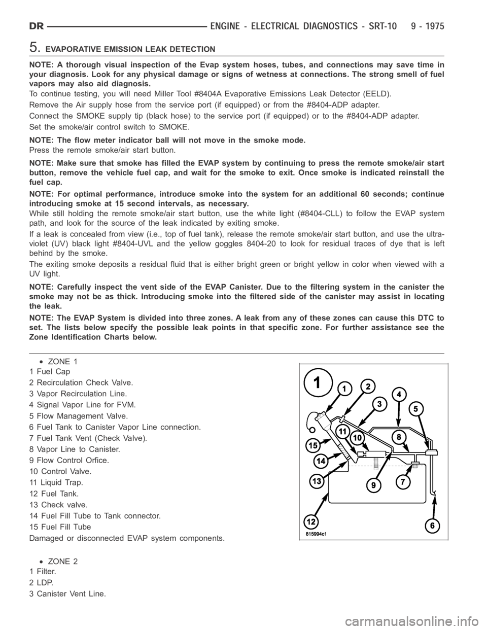
NOTE: The EVAP System is divided into three zones. A leak from any of these zonescancausethisDTCto
set. The lists below specify the possible leak points in that specific zone. For further assistance see the
Zone Identification Charts below.
ZONE 1
1FuelCap
2 Recirculation Check Valve.
3 Vapor Recirculation Line.
4 Signal Vapor Line for FVM.
5 Flow Management Valve.
6 Fuel Tank to Canister Vapor Line connection.
7 Fuel Tank Vent (Check Valve).
8 Vapor Line to Canister.
9 Flow Control Orfice.
10 Control Valve.
11 Liquid Trap.
12 Fuel Tank.
13 Check valve.
14 Fuel Fill Tube to Tank connector.
15 Fuel Fill Tube
Damaged or disconnected EVAP system components.
ZONE 2
1Filter.
2LDP.
3 Canister Vent Line.
Page 1484 of 5267
23. If thelift foot setsare continually used, a speed control overshoot/undershoot condition will develop.
24. To
unlearnthe overshoot/undershoot condition, the vehicle operator has to press and release the set button
while maintaining the desired set speedusing the accelerator pedal (not decelerating or accelerating).
25. Then turn the cruise control switch to the OFF position (or press the CANCEL button if equipped) after waiting
10 seconds.
26. This procedure must be performed approximately 10-15 times to completely unlearn the overshoot/undershoot
condition.
Did the Speed Control pass the above test?
Ye s>>
Repair is complete.
No>>
Check for any related Technical Service Bulletins and/or refer to the appropriate Diagnostic Procedure.
3.POWERTRAIN VERIFICATION TEST 2
1. If this vehicle is equipped with an Electronic Throttle Control system,and the APP Sensors, PCM, or Throttle
Body Assembly has been replaced use a scan tool to perform the ETC RELEARN function.
NOTE: 2. After completing the Powertrain Verification Test the Transmission Verification Test must be per-
formed.
NOTE: 3. If the PCM has been replaced and the correct VIN and mileage have notbeen programmed, a DTC
will set in the ABS Module, Airbag Module and the SKIM/SKREEM.
NOTE: 4. If the vehicle is equipped with a Sentry Key Remote Entry, Secret Key data must be updated. Refer
to the Service Information for the PCM, SKIM/SKREEM and the Transponder (ignition key) for programming
information. Using the scan tool, program the Secret Key information intothe PCM using the PCM replaced
function under the WCM menu.
5. Inspect the vehicle to make sure that all components related to the repair are properly installed and connected.
6. With the scan tool, clear DTCs.
7. Perform generator output test. Refer to the appropriate service information as necessary.
8. Start the engine and set engine speed to 2000 RPM for at least thirty seconds.
9. Cycle the ignition key off and on.
10. With the scan tool, read the DTCs.
Are any DTCs or symptoms remaining?
Ye s>>
Check for any Technical Service Bulletins and/or refer to the appropriateDiagnostic Procedure.
No>>
Repair is complete.
4.POWERTRAIN VERIFICATION TEST 3
1. Install the Miller Tool #8404 Evaporative Emission Leak Detector (EELD) according to the instructions in the pre-
vious DTC table.
2. Set the smoke/air control switch to AIR.
3. Insert the tester’s AIR supply tip (clear hose) into the appropriate calibration orifice on the tester’s control panel
(based on DTC leak size).
4. Press the remote smoke/air start button.
5. Position the red flag on the air flow meter so it is aligned with the indicator ball.
6. When the calibration is complete, release the remote button. The EELD flow meter is now calibrated in liters per
minute to the size of leak indicated by the DTC set in the PCM.
7. Install the service port adapter #8404-14 on the vehicle’s service port.
8. Connect the Air supply hose from the EELD to the vehicle.
9. Press the remote button to activate AIR flow.
NOTE: 10. Larger volume fuel tanks, lower fuel levels or if the vehicle is equipped with a Flow Management
Valve may indicate high flow and will require 4 to 5 minutes to fill.
11. Compare the flow meter indicator ball reading to the red flag.
12. ABOVE the red flag indicates a leak present.
13. BELOW the red flag indicates a sealed system.