Page 894 of 5267

*FUEL PUMP RETURN FLOW TEST
Possible Causes
EXCESSIVE FUEL PUMP RETURN FLOW
Diagnostic Test
1.FUEL PUMP RETURN FLOW TEST
Using the scan tool, idle the engine and measure the rail pressure and determine if the rail pressure is excessive
(above 185,00 kpa/26,831 psi), if it is, troubleshoot for excessive rail pressure first.
Remove the banjo bolt from the pressure-limiting valve on the fuel rail.
Install fuel system test fitting #9013 into the pressure-limiting valve.
Attach one end of a fuel hose to the fuel fitting and put the other end of the fuel hose into a container
Perform the tests listed below to determine if the pressure-limiting valve is leaking.
a. Operate the engine at idle and watch for fuel flow into the fuel container.
b. Operate the engine at idle and actuate the high pressure safety valve test with the scan tool. Watch for fuel flow
into the fuel container.
If fuel flows into the fuel container, replace the pressure-limiting valve. If fuel does not leak from the pressure-limiting
valve, the test is complete.
NOTE: do not drive the vehicle with any portion of this test kit installed
Operate the engine until the engine is at operating temperature.
Remove the banjo connector from the fuel drain tube at the rear of the fuel filter housing
Install fuel system test fitting #9012 in place of the banjo connector.
Install a piece of fuel line onto the test fitting and put the open end into the graduated cylinder.
Start the engine and let it idle for one minute.
Measure the amount of fuel in the graduated cylinder.
If the flow is less than 1000-ml/minute at idle, the test has successfully passed.
If the flow is greater than 1000 ml/minute at idle, replace the fuel injection pump.
Retest to confirm repair.
View Repair
Repair
Te s t C o m p l e t e .
Perform POWERTRAIN VERIFICATION TEST VER - 1 (DIESEL). (Refer to 8 - ELECTRICAL/ELEC-
TRONIC CONTROL MODULES/ENGINE CONTROL MODULE - DIAGNOSIS AND TESTING)
Page 1509 of 5267

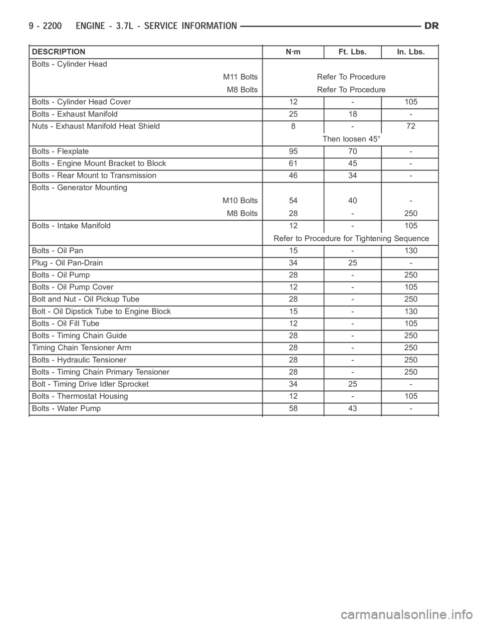
DESCRIPTION Nꞏm Ft. Lbs. In. Lbs.
Bolts - Cylinder Head
M11 Bolts Refer To Procedure
M8 Bolts Refer To Procedure
Bolts - Cylinder Head Cover 12 - 105
Bolts - Exhaust Manifold 25 18 -
Nuts - Exhaust Manifold Heat Shield 8 - 72
Then loosen 45°
Bolts - Flexplate 95 70 -
Bolts - Engine Mount Bracket to Block 61 45 -
Bolts - Rear Mount to Transmission 46 34 -
Bolts - Generator Mounting
M10 Bolts 54 40 -
M8 Bolts 28 - 250
Bolts - Intake Manifold 12 - 105
Refer to Procedure for Tightening Sequence
Bolts - Oil Pan 15 - 130
Plug - Oil Pan-Drain 34 25 -
Bolts - Oil Pump 28 - 250
Bolts - Oil Pump Cover 12 - 105
Bolt and Nut - Oil Pickup Tube 28 - 250
Bolt - Oil Dipstick Tube to Engine Block 15 - 130
Bolts - Oil Fill Tube 12 - 105
Bolts - Timing Chain Guide 28 - 250
Timing Chain Tensioner Arm 28 - 250
Bolts - Hydraulic Tensioner 28 - 250
Bolts - Timing Chain Primary Tensioner 28 - 250
Bolt - Timing Drive Idler Sprocket 34 25 -
Bolts - Thermostat Housing 12 - 105
Bolts - Water Pump 58 43 -
Page 1548 of 5267

COVER - CYLINDER HEAD
REMOVAL
1. Disconnect battery negative cable.
2. Remove air cleaner assembly, resonator assembly and air inlet hose.
3. Drain cooling system, below the level of the heater hoses (Refer to 7 - COOLING - STANDARD PROCEDURE).
4. Remove accessory drive belt (Refer to 7 - COOLING/ACCESSORY DRIVE/DRIVE BELTS - REMOVAL).
5. Remove air conditioning compressor retaining bolts and move compressortotheleft.
6. Remove heater hoses.
7. Disconnect injector and ignition coil connectors.
8. Disconnect and remove positive crankcase ventilation (PCV) hose.
9. Remove oil fill tube.
10. Un-clip injector and ignition coil harness and move away from cylinderhead cover.
11. Remove right rear breather tube and filter assembly.
12. Remove cylinder head cover retaining bolts.
13. Remove cylinder head cover.
INSTALLATION
CAUTION: Do not use harsh cleaners to clean the cylinder head covers. Severedamagetocoversmay
occur.
NOTE: The gasket may be used again, provided no cuts, tears, or deformationhas occurred.
1. Clean cylinder head cover and both sealing surfaces. Inspect and replace gasket as necessary.
2. Tighten cylinder head cover bolts and double ended studs to 12 Nꞏm (105 in.lbs).
3. Install right rear breather tube and filter assembly.
4. Connect injector, ignition coil electrical connectors and harness retaining clips.
5. Install the oil fill tube.
6. Install PCV hose.
7. Install heater hoses.
8. Install air conditioning compressor retaining bolts.
9. Install accessory drive belt (Refer to 7 - COOLING/ACCESSORY DRIVE/DRIVE BELTS - INSTALLATION).
10. Fill Cooling system (Refer to 7 - COOLING - STANDARD PROCEDURE).
11. Install air cleaner assembly, resonator assembly and air inlet hose.
12. Connect battery negative cable.
Page 1562 of 5267
SEAL-CRANKSHAFT OIL-FRONT
REMOVAL
1. Disconnect negative cable from battery.
2. Remove accessory drive belt (Refer to 7 - COOL-
ING/ACCESSORY DRIVE/DRIVE BELTS -
REMOVAL).
3. Remove A/C compressor mouning fasteners and
set aside.
4. Drain cooling system (Refer to 7 - COOLING -
STANDARD PROCEDURE).
5. Remove upper radiator hose.
6. Disconnect electrical connector for fan mounted
inside radiator shroud.
7. Remove radiator shroud attaching fasteners.
NOTE: Transmission cooler line snaps into shroud
lower right hand corner.
8. Remove radiator cooling fan and shroud (Refer to
7 - COOLING/ENGINE/RADIATOR FAN -
REMOVAL).
9. Remove crankshaft damper bolt.
10. Remove damper using Special Tools 8513 Insert
and 1026 Three Jaw Puller (2).
11. Using Special Tool 8511 (1), remove crankshaft
front seal.
Page 1577 of 5267
DAMPER-CRANKSHAFT
REMOVAL
1. Disconnect negative cable from battery.
2. Remove accessory drive belt (Refer to 7 - COOL-
ING/ACCESSORY DRIVE/DRIVE BELTS -
REMOVAL).
3. Drain cooling system (Refer to 7 - COOLING -
STANDARD PROCEDURE).
4. Remove radiator upper hose.
5. Remove upper fan shroud.
6. Using Special Tools 6958 Spanner with Adapter
Pins 8346 (1), loosen fan and viscous assembly
from water pump.
7. Remove fan and viscous assembly.
8. Disconnect electrical connector for fan mounted
inside radiator shroud.
NOTE: Transmission cooler line snaps into shroud
lower right hand corner.
9. Remove crankshaft damper bolt.
10. Remove damper using Special Tools 8513 Insert
and 1026 Three Jaw Puller (2).
Page 1580 of 5267

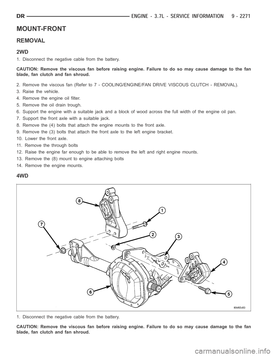
MOUNT-FRONT
REMOVAL
2WD
1. Disconnect the negative cable from the battery.
CAUTION: Remove the viscous fan before raising engine. Failure to do so maycause damage to the fan
blade, fan clutch and fan shroud.
2. Remove the viscous fan (Refer to 7 - COOLING/ENGINE/FAN DRIVE VISCOUS CLUTCH - REMOVAL).
3. Raise the vehicle.
4. Remove the engine oil filter.
5. Remove the oil drain trough.
6. Support the engine with a suitable jack and a block of wood across the fullwidth of the engine oil pan.
7. Support the front axle with a suitable jack.
8. Remove the (4) bolts that attach the engine mounts to the front axle.
9. Remove the (3) bolts that attach the front axle to the left engine bracket.
10. Lower the front axle.
11. Remove the through bolts
12. Raise the engine far enough to be able to remove the left and right enginemounts.
13. Remove the (8) mount to engine attaching bolts
14. Remove the engine mounts.
4WD
1. Disconnect the negative cable from the battery.
CAUTION: Remove the viscous fan before raising engine. Failure to do so maycause damage to the fan
blade, fan clutch and fan shroud.
Page 1581 of 5267
2. Remove the viscous fan (Refer to 7 - COOLING/ENGINE/FAN DRIVE VISCOUS CLUTCH - REMOVAL).
3. Raise the vehicle.
4. Removetheskidplate.
5. Remove the front crossmember.
6. Remove the engine oil filter.
7. Remove the oil drain trough.
8. Support the engine with a suitable jack and a block of wood across the fullwidth of the engine oil pan.
9. Support the front axle with a suitable jack.
10. Remove the 4 bolts that attach the engine mounts to the front axle.
11. Remove the 3 bolts that attach the front axle to the left engine bracket.
12. Lower the front axle.
13. Remove the 6 through bolts
14. Raise the engine far enough to be able to remove the left (4) and right (8)engine mounts.
15. Remove the mounts.
Page 1582 of 5267
16. Remove the engine mount brackets and (2).
INSTALLATION
2WD
NOTE: For mount to engine block and left engine bracket to front axle bolts,apply MoparLock and Seal
Adhesive, Medium Strength Threadlocker.
1. Install the right and left side engine mounts to the engine block with (8)bolts. Torque bolts to 54 Nꞏm (40 ft. lbs.).
2. Insert the (2) through bolts into the right and left side engine mounts and loose assemble the two nuts onto the
through bolts.
3. Lower the engine until the through bolts rest onto the slots in the frame brackets.
4. Tighten the through bolt nuts to 94 Nꞏm (70 ft. lbs.).
5. Install the oil drain trough.
6. Install the engine oil filter.
7. Lower the vehicle.
8. Install the viscous fan (Refer to 7 - COOLING/ENGINE/FAN DRIVE VISCOUS CLUTCH - REMOVAL).
9. Reconnect the negative battery cable.