Page 2127 of 5267
ALTERNATIVE METHOD
1. With the weight of the crankshaft being supported
by a jack under the counterweight adjacent to the
bearing being checked.
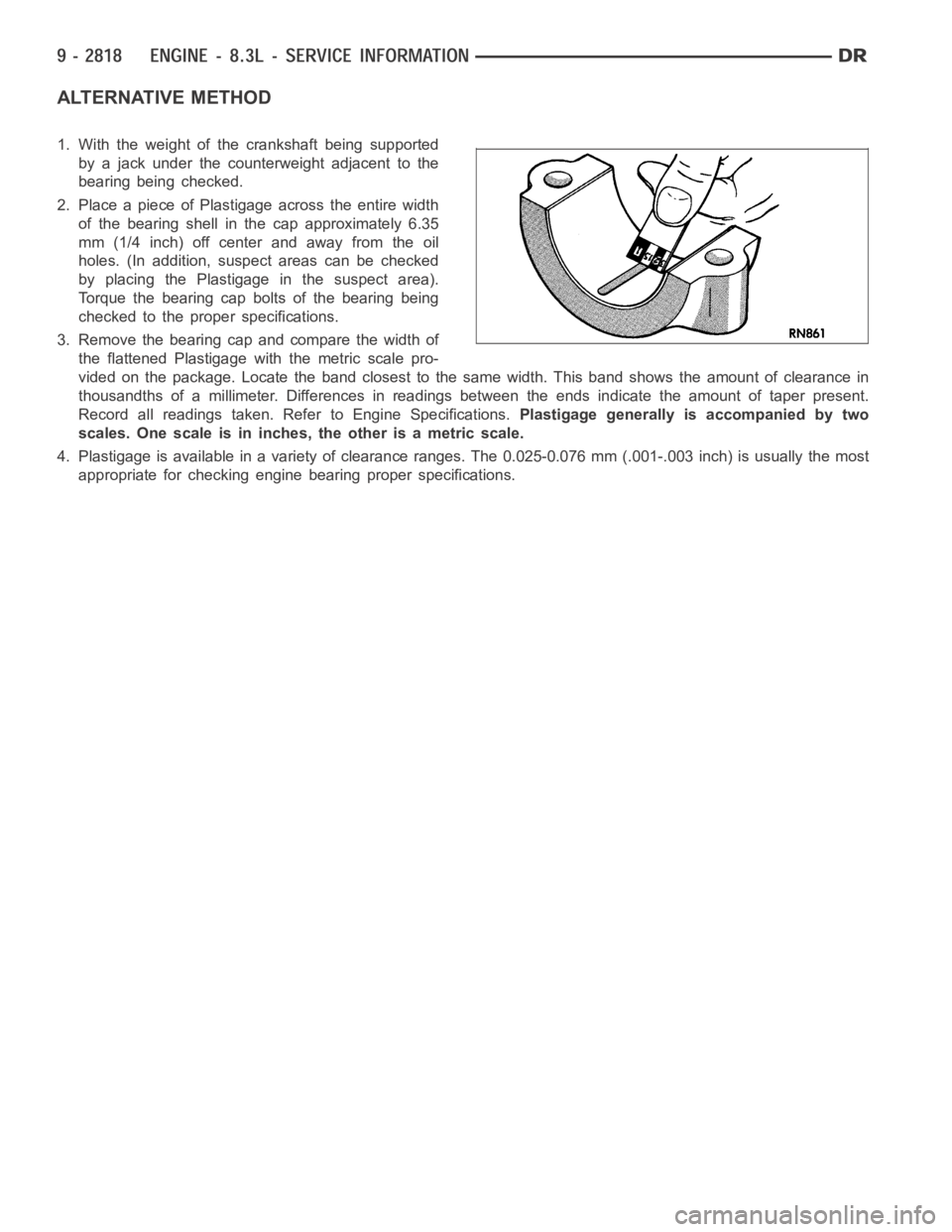
2. Place a piece of Plastigage across the entire width
of the bearing shell in the cap approximately 6.35
mm (1/4 inch) off center and away from the oil
holes. (In addition, suspect areas can be checked
by placing the Plastigage in the suspect area).
Torque the bearing cap bolts of the bearing being
checked to the proper specifications.
3. Remove the bearing cap and compare the width of
the flattened Plastigage with the metric scale pro-
vided on the package. Locate the band closest to the same width. This band shows the amount of clearance in
thousandths of a millimeter. Differences in readings between the ends indicate the amount of taper present.
Record all readings taken. Refer to Engine Specifications.Plastigage generally is accompanied by two
scales. One scale is in inches, the other is a metric scale.
4. Plastigage is available in a variety of clearance ranges. The 0.025-0.076 mm (.001-.003 inch) is usually the most
appropriate for checking engine bearing proper specifications.
Page 2940 of 5267
35. Remove the front carrier/rear annulus (2) and #6
needle bearing (1).
36. Remove the rear sun gear (2) and #7 needle
bearing (1).
NOTE: The number seven needle bearing (1) has
three antireversal tabs and is common with the
number five and number two position. The orien-
tation should allow the bearing to seat flat against
the rear sun gear. A small amount of petrolatum
can be used to hold the bearing to the rear sun
gear.
Page 2961 of 5267
34.Measure 2/4 clutch clearance:Set up dial indi-
cator (1) as shown. Press down clutch pack with
finger and zero dial indicator. Record measure-
ment in four (4) places and take average reading.
The 2/4 clutch pack clearance is 0.76 to 2.64
mm (0.030 to 0.104 inch).If not within specifica-
tions, the clutch is not assembled properly or is
excessively worn.There is no adjustment for
the 2/4 clutch clearance.
35. Install the #7 needle bearing (1) to the rear sun
gear (2).The number 7 needle bearing has
three antireversal tabs and is common with
the number 5 and number 2 position. The ori-
entation should allow the bearing to seat flat
against the rear sun gear. A small amount of
petrolatum can be used to hold the bearing to
the rear sun gear.
36. Install rear sun gear (2) and #7 needle bearing
(1).
Page 3940 of 5267
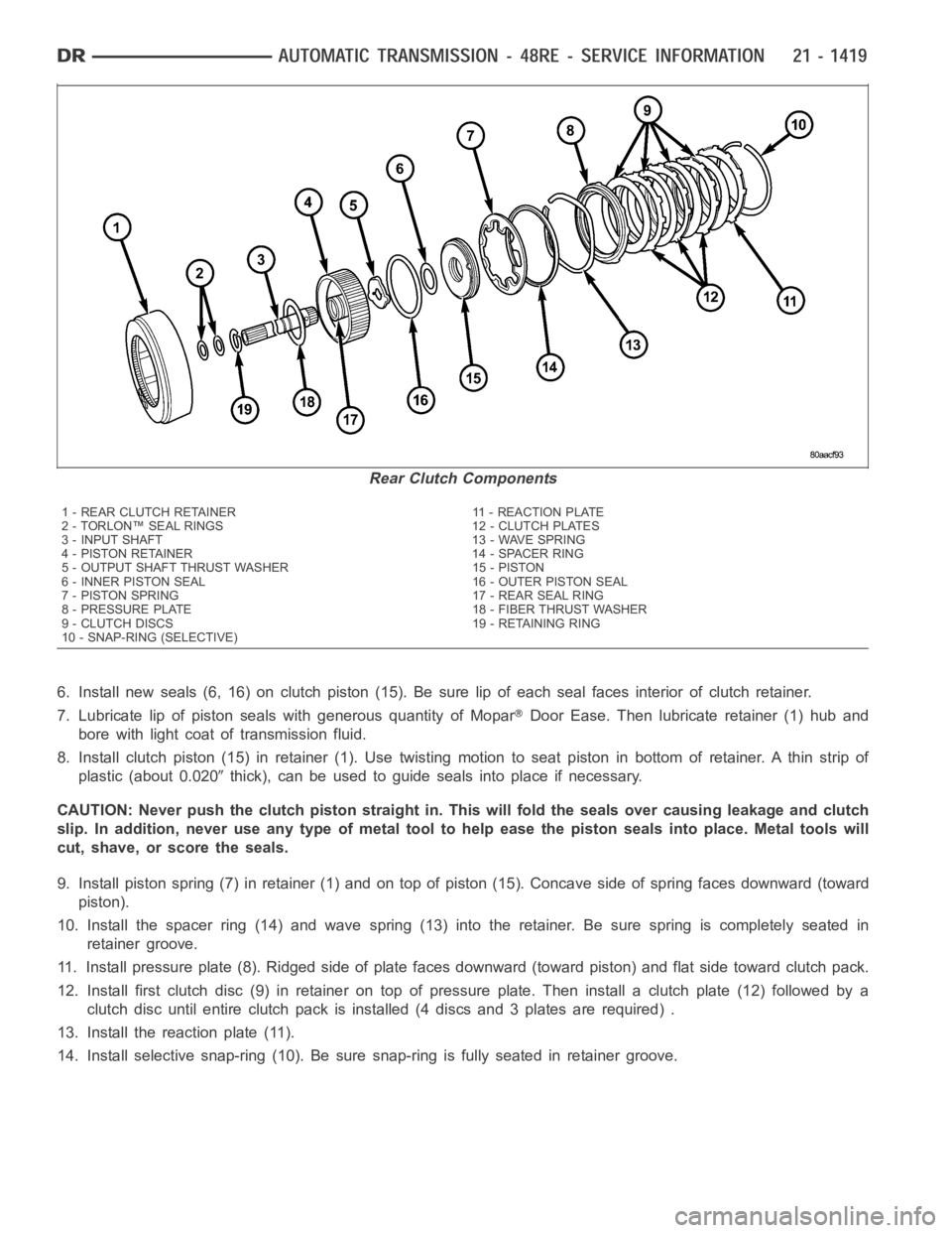
6. Install new seals (6, 16) on clutch piston (15). Be sure lip of each seal faces interior of clutch retainer.
7. Lubricate lip of piston seals with generous quantity of Mopar
Door Ease. Then lubricate retainer (1) hub and
bore with light coat of transmission fluid.
8. Install clutch piston (15) in retainer (1). Use twisting motion to seat piston in bottom of retainer. A thin strip of
plastic (about 0.020
thick), can be used to guide seals into place if necessary.
CAUTION: Never push the clutch piston straight in. This will fold the sealsover causing leakage and clutch
slip. In addition, never use any type of metal tool to help ease the piston seals into place. Metal tools will
cut, shave, or score the seals.
9. Install piston spring (7) in retainer (1) and on top of piston (15). Concave side of spring faces downward (toward
piston).
10. Install the spacer ring (14) and wave spring (13) into the retainer. Be sure spring is completely seated in
retainer groove.
11. Install pressure plate (8). Ridged side of plate faces downward (toward piston) and flat side toward clutch pack.
12. Install first clutch disc (9) in retainer on top of pressure plate. Theninstall a clutch plate (12) followed by a
clutch disc until entire clutch pack is installed (4 discs and 3 plates are required) .
13. Install the reaction plate (11).
14. Install selective snap-ring (10). Be sure snap-ring is fully seated inretainer groove.
Rear Clutch Components
1 - REAR CLUTCH RETAINER 11 - REACTION PLATE
2 - TORLON™ SEAL RINGS 12 - CLUTCH PLATES
3 - INPUT SHAFT 13 - WAVE SPRING
4 - PISTON RETAINER 14 - SPACER RING
5 - OUTPUT SHAFT THRUST WASHER 15 - PISTON
6 - INNER PISTON SEAL 16 - OUTER PISTON SEAL
7 - PISTON SPRING 17 - REAR SEAL RING
8 - PRESSURE PLATE 18 - FIBER THRUST WASHER
9 - CLUTCH DISCS 19 - RETAINING RING
10 - SNAP-RING (SELECTIVE)
Page 4314 of 5267
TIRES/WHEELS
TABLE OF CONTENTS
page page
TIRES/WHEELS
DIAGNOSIS AND TESTING
TIRE AND WHEEL RUNOUT .................. 2
STANDARD PROCEDURE
MATCH MOUNTING .......................... 4
TIRE AND WHEEL BALANCE ................. 5
TIRE ROTATION ............................. 6
SPECIFICATIONS
TORQUE .................................... 7
TIRES
DESCRIPTION
TIRES ....................................... 8
SPARE / TEMPORARY TIRE .................. 8
RADIAL – PLY TIRES ......................... 8
TIRE PRESSURE FOR HIGH SPEEDS......... 9
REPLACEMENT TIRES ....................... 9
TIRE INFLATION PRESSURES ................ 9
DIAGNOSIS AND TESTING
PRESSURE GAUGES ....................... 10
TIRE NOISE OR VIBRATION ................. 10
TREAD WEAR INDICATORS ................. 10
TIRE WEAR PATTERNS ..................... 11
TIRE/VEHICLE LEAD ........................ 12
STANDARD PROCEDURE
TIRE REPAIR AREA ......................... 13
CLEANING
TIRES ..................................... 13SPECIFICATIONS
TIRE REVOLUTIONS PER MILE .............. 13
WHEELS
DESCRIPTION
DESCRIPTION .............................. 15
WHEEL DESIGN ............................ 16
DIAGNOSIS AND TESTING
WHEEL INSPECTION....................... 16
STANDARD PROCEDURE
WHEEL REPLACEMENT ..................... 16
DUAL REAR WHEEL INSTALLATION .......... 18
STUDS
REMOVAL .................................... 20
INSTALLATION ............................... 20
WHEEL COVER
REMOVAL .................................... 22
INSTALLATION
REAR ...................................... 22
FRONT .................................... 22
SPARE TIRE
DESCRIPTION
SPARE / TEMPORARY TIRE ................. 23
FULL SIZE, SPARE WHEEL WITH
MATCHING TIRE............................ 23
Page 4316 of 5267
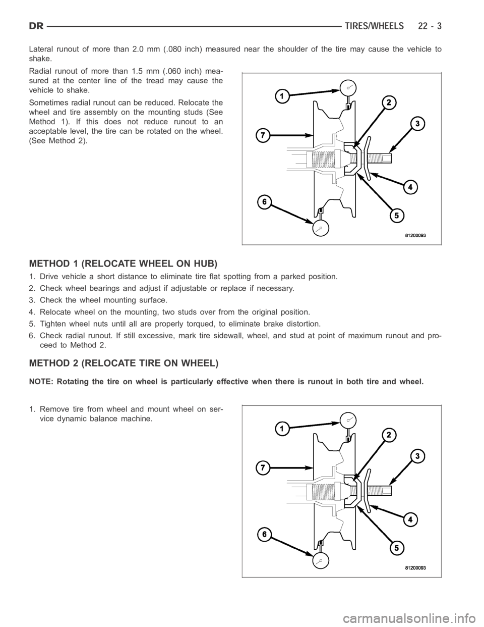
Lateral runout of more than 2.0 mm (.080 inch) measured near the shoulder ofthetiremaycausethevehicleto
shake.
Radial runout of more than 1.5 mm (.060 inch) mea-
sured at the center line of the tread may cause the
vehicle to shake.
Sometimes radial runout can be reduced. Relocate the
wheel and tire assembly on the mounting studs (See
Method 1). If this does not reduce runout to an
acceptable level, the tire can be rotated on the wheel.
(See Method 2).
METHOD 1 (RELOCATE WHEEL ON HUB)
1. Drive vehicle a short distance to eliminate tire flat spotting from a parked position.
2. Check wheel bearings and adjust if adjustable or replace if necessary.
3. Check the wheel mounting surface.
4. Relocate wheel on the mounting, two studs over from the original position.
5. Tighten wheel nuts until all are properly torqued, to eliminate brake distortion.
6. Check radial runout. If still excessive, mark tire sidewall, wheel, andstud at point of maximum runout and pro-
ceed to Method 2.
METHOD 2 (RELOCATE TIRE ON WHEEL)
NOTE: Rotating the tire on wheel is particularly effective when there is runout in both tire and wheel.
1. Remove tire from wheel and mount wheel on ser-
vice dynamic balance machine.
Page 4320 of 5267
CAUTION: 3500 Dual rear tires have a new tire
rotation pattern. This is to accommodate the out-
lined white letter (OWL) tires. When replacing a
flat, the spare tire may have to be remounted on
the rim or installed at a different location to main-
tain the correct placement of the outlined white
letter (OWL) tires.
The recommended method of tire rotation for dual rear
wheel is. Other methods can be used, but may not
provide the same tire longevity benefits.
SPECIFICATIONS
TORQUE
DESCRIPTION Nꞏm Ft. Lbs. In. Lbs.
1500 Series
Lug Nut 9/16 X 18 with
60° Cone
LD176 130 —
2500 Series
Lug Nut 9/16 X 18 with
60° Cone
HD SRW190 140 —
3500 Series
Lug Nut 9/16 X 18 with
Flat Washer
HD DRW197 145 —
Page 4322 of 5267
Radial-ply tires have the same load-carrying capacity as other types of tires of the same size. They also use the
same recommended inflation pressures.
The use of oversized tires, either in the front or rear of the vehicle, can cause vehicle drive train failure. This could
also cause inaccurate wheel speed signals when the vehicle is equipped with Anti-Lock Brakes.
The use of tires from different manufactures on the same vehicle is NOT recommended. The proper tire pressure
should be maintained on all four tires.
TIRE PRESSURE FOR HIGH SPEEDS
For proper tire pressure specification refer to the Owners Manual.
REPLACEMENT TIRES
The original equipment tires provide a proper balance of many characteristics such as:
Ride
Noise
Handling
Durability
Tread life
Traction
Rolling resistance
Speed capability
It is recommended that tires equivalent to the original equipment tires beused when replacement is needed.
Failure to use equivalent replacement tires may adversely affect the safety and handling of the vehicle.
The use of oversize tires may cause interference with vehicle components.Under extremes of suspension and
steering travel, interference with vehicle components may cause tire damage.
WARNING: Failure to equip the vehicle with tires having adequate speed capability can result in sudden tire
failure.
TIRE INFLATION PRESSURES
WARNING: Over or under inflated tires can affect
vehicle handling and tread wear. This may cause
the tire to fail suddenly, resulting in loss of vehicle
control.
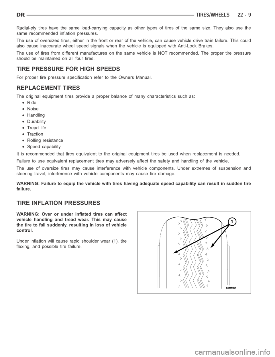
Under inflation will cause rapid shoulder wear (1), tire
flexing, and possible tire failure.