2006 DODGE RAM SRT-10 run flat
[x] Cancel search: run flatPage 1508 of 5267
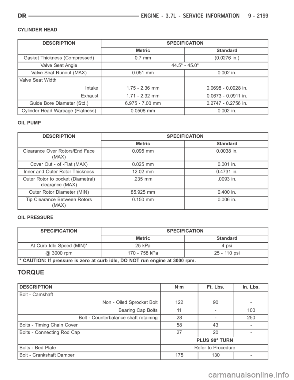
CYLINDER HEAD
DESCRIPTION SPECIFICATION
Metric Standard
Gasket Thickness (Compressed) 0.7 mm (0.0276 in.)
Valve Seat Angle 44.5° - 45.0°
Valve Seat Runout (MAX) 0.051 mm 0.002 in.
Va l v e S e a t W i d t h
Intake 1.75 - 2.36 mm 0.0698 - 0.0928 in.
Exhaust 1.71 - 2.32 mm 0.0673 - 0.0911 in.
Guide Bore Diameter (Std.) 6.975 - 7.00 mm 0.2747 - 0.2756 in.
Cylinder Head Warpage (Flatness) 0.0508 mm 0.002 in.
OIL PUMP
DESCRIPTION SPECIFICATION
Metric Standard
Clearance Over Rotors/End Face
(MAX)0.095 mm 0.0038 in.
Cover Out - of -Flat (MAX) 0.025 mm 0.001 in.
Inner and Outer Rotor Thickness 12.02 mm 0.4731 in.
Outer Rotor to pocket (Diametral)
clearance (MAX).235 mm .0093 in.
Outer Rotor Diameter (MIN) 85.925 mm 0.400 in.
Tip Clearance Between Rotors
(MAX)0.150 mm 0.006 in.
OIL PRESSURE
SPECIFICATION SPECIFICATION
Metric Standard
At Curb Idle Speed (MIN)* 25 kPa 4 psi
@ 3000 rpm 170 - 758 kPa 25 - 110 psi
* CAUTION: If pressure is zero at curb idle, DO NOT run engine at 3000 rpm.
TORQUE
DESCRIPTION Nꞏm Ft. Lbs. In. Lbs.
Bolt - Camshaft
Non - Oiled Sprocket Bolt 122 90 -
Bearing Cap Bolts 11 - 100
Bolt - Counterbalance shaft retaining 28 - 250
Bolts - Timing Chain Cover 58 43 -
Bolts - Connecting Rod Cap 27 20 -
PLUS 90° TURN
Bolts - Bed Plate Refer to Procedure
Bolt - Crankshaft Damper 175 130 -
Page 1644 of 5267
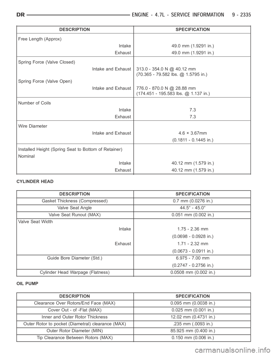
DESCRIPTION SPECIFICATION
Free Length (Approx)
Intake 49.0 mm (1.9291 in.)
Exhaust 49.0 mm (1.9291 in.)
Spring Force (Valve Closed)
Intake and Exhaust 313.0 - 354.0 N @ 40.12 mm
(70.365 - 79.582 lbs. @ 1.5795 in.)
Spring Force (Valve Open)
Intake and Exhaust 776.0 - 870.0 N @ 28.88 mm
(174.451 - 195.583 lbs. @ 1.137 in.)
Number of Coils
Intake 7.3
Exhaust 7.3
Wire Diameter
Intake and Exhaust 4.6 × 3.67mm
(0.1811 - 0.1445 in.)
Installed Height (Spring Seat to Bottom of Retainer)
Nominal
Intake 40.12 mm (1.579 in.)
Exhaust 40.12 mm (1.579 in.)
CYLINDER HEAD
DESCRIPTION SPECIFICATION
Gasket Thickness (Compressed) 0.7 mm (0.0276 in.)
Valve Seat Angle 44.5° - 45.0°
Valve Seat Runout (MAX) 0.051 mm (0.002 in.)
Va l v e S e a t W i d t h
Intake 1.75 - 2.36 mm
(0.0698 - 0.0928 in.)
Exhaust 1.71 - 2.32 mm
(0.0673 - 0.0911 in.)
Guide Bore Diameter (Std.) 6.975 - 7.00 mm
(0.2747 - 0.2756 in.)
Cylinder Head Warpage (Flatness) 0.0508 mm (0.002 in.)
OIL PUMP
DESCRIPTION SPECIFICATION
Clearance Over Rotors/End Face (MAX) 0.095 mm (0.0038 in.)
Cover Out - of -Flat (MAX) 0.025 mm (0.001 in.)
Inner and Outer Rotor Thickness 12.02 mm (0.4731 in.)
Outer Rotor to pocket (Diametral) clearance (MAX) .235 mm (.0093 in.)
Outer Rotor Diameter (MIN) 85.925 mm (0.400 in.)
Tip Clearance Between Rotors (MAX) 0.150 mm (0.006 in.)
Page 1964 of 5267
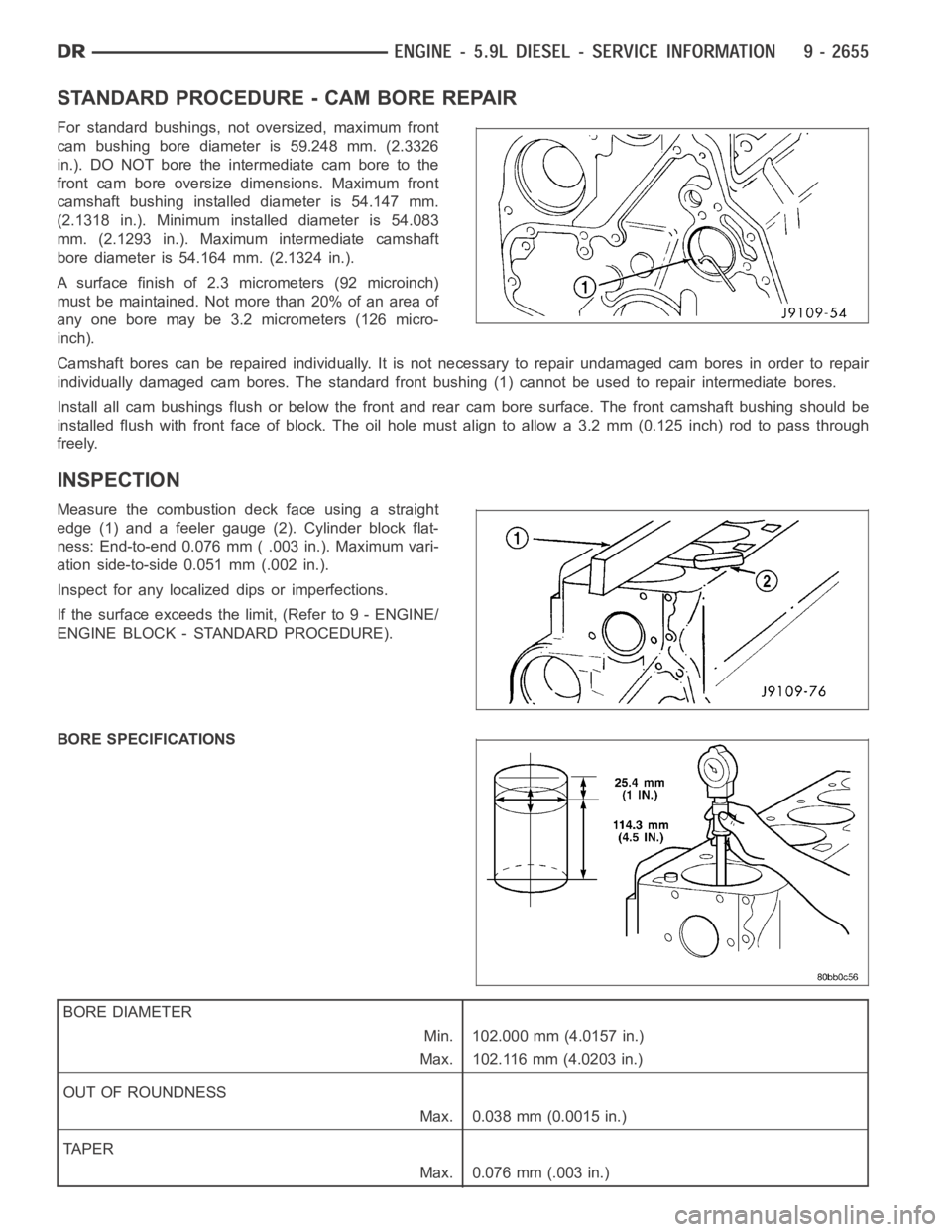
STANDARD PROCEDURE - CAM BORE REPAIR
For standard bushings, not oversized, maximum front
cam bushing bore diameter is 59.248 mm. (2.3326
in.). DO NOT bore the intermediate cam bore to the
front cam bore oversize dimensions. Maximum front
camshaft bushing installed diameter is 54.147 mm.
(2.1318 in.). Minimum installed diameter is 54.083
mm. (2.1293 in.). Maximum intermediate camshaft
bore diameter is 54.164 mm. (2.1324 in.).
A surface finish of 2.3 micrometers (92 microinch)
must be maintained. Not more than 20% of an area of
any one bore may be 3.2 micrometers (126 micro-
inch).
Camshaft bores can be repaired individually. It is not necessary to repairundamaged cam bores in order to repair
individually damaged cam bores. The standard front bushing (1) cannot be used to repair intermediate bores.
Install all cam bushings flush or below the front and rear cam bore surface.The front camshaft bushing should be
installed flush with front face of block. The oil hole must align to allow a 3.2 mm (0.125 inch) rod to pass through
freely.
INSPECTION
Measure the combustion deck face using a straight
edge (1) and a feeler gauge (2). Cylinder block flat-
ness: End-to-end 0.076 mm ( .003 in.). Maximum vari-
ation side-to-side 0.051 mm (.002 in.).
Inspect for any localized dips or imperfections.
If the surface exceeds the limit, (Refer to 9 - ENGINE/
ENGINE BLOCK - STANDARD PROCEDURE).
BORE SPECIFICATIONS
BORE DIAMETER
Min. 102.000 mm (4.0157 in.)
Max. 102.116 mm (4.0203 in.)
OUT OF ROUNDNESS
Max. 0.038 mm (0.0015 in.)
TA P E R
Max. 0.076 mm (.003 in.)
Page 3323 of 5267
6.CHECK TO SEE IF DTC P1736 IS CURRENT
With the scan tool, perform the 2nd Prime Gear Clutch Test. Follow the instructions on the scan tool.
Increase the throttle angle, TPS Degree, to 30° for no more than a few seconds.
CAUTION: Do not overheat the transmission.
NOTE: If the 4C clutch is faulty, the overrunning clutch will hold and the slip test will pass. The 2nd Prime
Gear Clutch Test will not detect a faulty 4C clutch. However, it will detectafaultyUDclutch.
Did the clutch test pass, did the Input Speed remain at zero?
Ye s>>
Go To 7
No>>
Go To 9
7.CHECK FOR INTERMITTENT OPERATION
Check the Shifter adjustment per the Service Information.
Intermittent gear ratio DTCs can be set by problems in the Input and Output Speed Sensor circuits and/or Speed
Sensor Ground circuit.
Check the Speed Sensor wiring and connectors for good connection, then performawiggletestusingtheTrans-
mission Simulator, Miller tool #8333.
Were there any problems found?
Ye s>>
Repair as necessary.
Perform 45RFE/545RFE TRANSMISSION VERIFICATION TEST - VER 1. (Refer to 21- TRANSMIS-
SION/TRANSAXLE/AUTOMATIC - 45RFE/545RFE - STANDARD PROCEDURE)
No>>
Go To 8
8.CHECK FOR SLIPPAGE
With the scan tool, erase Transmission DTCs.
Road test the vehicle.
During the road test, operate in 4th gear, and perform kickdown shifts from4th to 2nd (prime) gears.
Is there an obvious slippage noticed in 4th or 2nd prime gears, or runaway onthe 4-2 shift?
Ye s>>
Go To 11
No>>
Go To 14
9.UD CLUTCH HYDRAULIC CIRCUIT
Remove Transmission Oil Pan and check for excessive debris.
Remove the Valve Body and air check the UD clutch hydraulic circuit (in the case) per the Service Information.
NOTE: The UD clutch passage contains a small bleed orifice, a small amount of air leakage is normal.
Were there any problems found, excessive debris and/or excessive air leakage in the UD clutch hydrau-
lic circuit?
Ye s>>
Repair as necessary. Check the UD clutch piston seals and the dribbler assembly, reaction shaft sup-
port seal rings, and the flatness of the pump valve body and pump housing faces. Check main regulator
valve for sticking in the bore.
Perform 45RFE/545RFE TRANSMISSION VERIFICATION TEST - VER 1. (Refer to 21- TRANSMIS-
SION/TRANSAXLE/AUTOMATIC - 45RFE/545RFE - STANDARD PROCEDURE)
No>>
Go To 10
Page 3384 of 5267
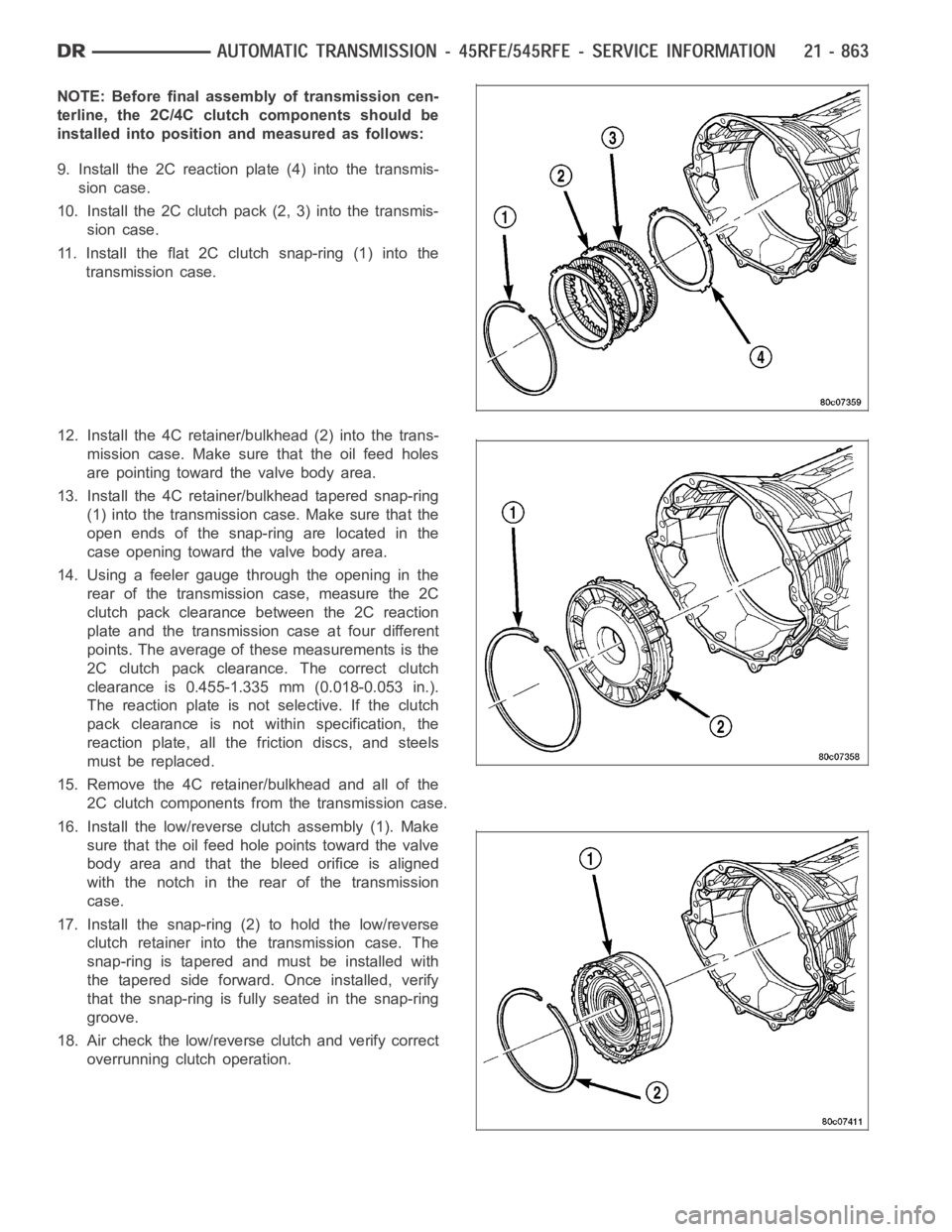
NOTE: Before final assembly of transmission cen-
terline, the 2C/4C clutch components should be
installed into position and measured as follows:
9. Install the 2C reaction plate (4) into the transmis-
sion case.
10. Install the 2C clutch pack (2, 3) into the transmis-
sion case.
11. Install the flat 2C clutchsnap-ring(1)intothe
transmission case.
12. Install the 4C retainer/bulkhead (2) into the trans-
mission case. Make sure that the oil feed holes
are pointing toward the valve body area.
13. Install the 4C retainer/bulkhead tapered snap-ring
(1) into the transmission case. Make sure that the
open ends of the snap-ring are located in the
case opening toward the valve body area.
14. Using a feeler gauge through the opening in the
rear of the transmission case, measure the 2C
clutch pack clearance between the 2C reaction
plate and the transmission case at four different
points. The average of these measurements is the
2C clutch pack clearance. The correct clutch
clearance is 0.455-1.335 mm (0.018-0.053 in.).
The reaction plate is not selective. If the clutch
pack clearance is not within specification, the
reaction plate, all the friction discs, and steels
must be replaced.
15. Remove the 4C retainer/bulkhead and all of the
2C clutch components from the transmission case.
16. Install the low/reverse clutch assembly (1). Make
sure that the oil feed hole points toward the valve
body area and that the bleed orifice is aligned
with the notch in the rear of the transmission
case.
17. Install the snap-ring (2) to hold the low/reverse
clutch retainer into the transmission case. The
snap-ring is tapered and must be installed with
the tapered side forward. Once installed, verify
that the snap-ring is fully seated in the snap-ring
groove.
18. Air check the low/reverse clutch and verify correct
overrunning clutch operation.
Page 3457 of 5267
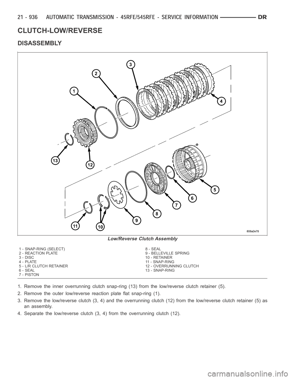
CLUTCH-LOW/REVERSE
DISASSEMBLY
1. Remove the inner overrunning clutch snap-ring (13) from the low/reverse clutch retainer (5).
2. Remove the outer low/reverse reaction plate flat snap-ring (1).
3. Remove the low/reverse clutch (3, 4) and the overrunning clutch (12) from the low/reverse clutch retainer (5) as
an assembly.
4. Separate the low/reverse clutch (3, 4) from the overrunning clutch (12).
Low/Reverse Clutch Assembly
1 - SNAP-RING (SELECT) 8 - SEAL
2 - REACTION PLATE 9 - BELLEVILLE SPRING
3 - DISC 10 - RETAINER
4 - PLATE 11 - SNAP-RING
5 - L/R CLUTCH RETAINER 12 - OVERRUNNING CLUTCH
6 - SEAL 13 - SNAP-RING
7-PISTON
Page 3460 of 5267
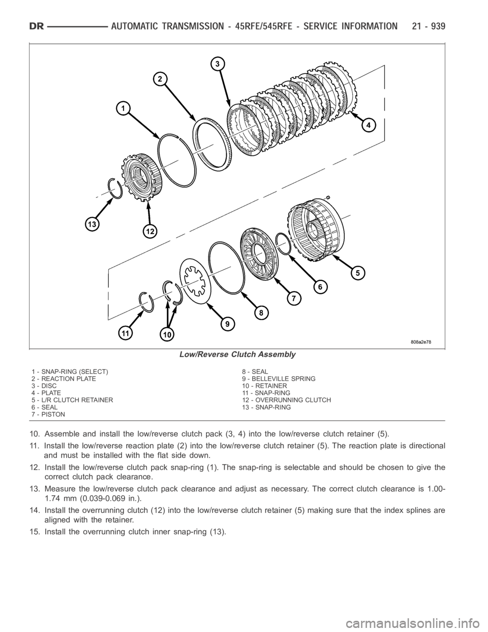
10. Assemble and install the low/reverse clutch pack (3, 4) into the low/reverse clutch retainer (5).
11. Install the low/reverse reaction plate (2) into the low/reverse clutch retainer (5). The reaction plate is directional
and must be installed with the flat side down.
12. Install the low/reverse clutch pack snap-ring (1). The snap-ring is selectable and should be chosen to give the
correct clutch pack clearance.
13. Measure the low/reverse clutch pack clearance and adjust as necessary. The correct clutch clearance is 1.00-
1.74 mm (0.039-0.069 in.).
14. Install the overrunning clutch (12) into the low/reverse clutch retainer (5) making sure that the index splines are
aligned with the retainer.
15. Install the overrunning clutch inner snap-ring (13).
Low/Reverse Clutch Assembly
1 - SNAP-RING (SELECT) 8 - SEAL
2 - REACTION PLATE 9 - BELLEVILLE SPRING
3 - DISC 10 - RETAINER
4 - PLATE 11 - SNAP-RING
5 - L/R CLUTCH RETAINER 12 - OVERRUNNING CLUTCH
6 - SEAL 13 - SNAP-RING
7-PISTON
Page 4314 of 5267
TIRES/WHEELS
TABLE OF CONTENTS
page page
TIRES/WHEELS
DIAGNOSIS AND TESTING
TIRE AND WHEEL RUNOUT .................. 2
STANDARD PROCEDURE
MATCH MOUNTING .......................... 4
TIRE AND WHEEL BALANCE ................. 5
TIRE ROTATION ............................. 6
SPECIFICATIONS
TORQUE .................................... 7
TIRES
DESCRIPTION
TIRES ....................................... 8
SPARE / TEMPORARY TIRE .................. 8
RADIAL – PLY TIRES ......................... 8
TIRE PRESSURE FOR HIGH SPEEDS......... 9
REPLACEMENT TIRES ....................... 9
TIRE INFLATION PRESSURES ................ 9
DIAGNOSIS AND TESTING
PRESSURE GAUGES ....................... 10
TIRE NOISE OR VIBRATION ................. 10
TREAD WEAR INDICATORS ................. 10
TIRE WEAR PATTERNS ..................... 11
TIRE/VEHICLE LEAD ........................ 12
STANDARD PROCEDURE
TIRE REPAIR AREA ......................... 13
CLEANING
TIRES ..................................... 13SPECIFICATIONS
TIRE REVOLUTIONS PER MILE .............. 13
WHEELS
DESCRIPTION
DESCRIPTION .............................. 15
WHEEL DESIGN ............................ 16
DIAGNOSIS AND TESTING
WHEEL INSPECTION....................... 16
STANDARD PROCEDURE
WHEEL REPLACEMENT ..................... 16
DUAL REAR WHEEL INSTALLATION .......... 18
STUDS
REMOVAL .................................... 20
INSTALLATION ............................... 20
WHEEL COVER
REMOVAL .................................... 22
INSTALLATION
REAR ...................................... 22
FRONT .................................... 22
SPARE TIRE
DESCRIPTION
SPARE / TEMPORARY TIRE ................. 23
FULL SIZE, SPARE WHEEL WITH
MATCHING TIRE............................ 23