2006 DODGE RAM SRT-10 cooling
[x] Cancel search: coolingPage 309 of 5267

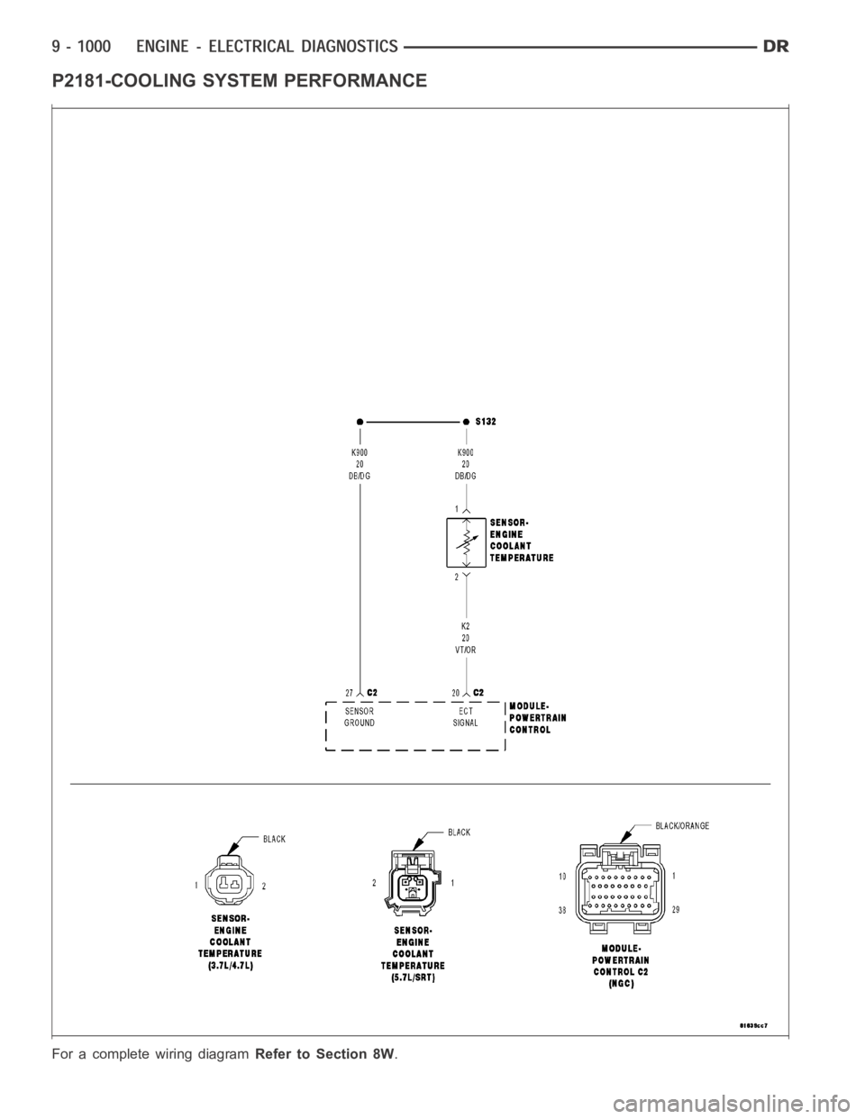
P2181-COOLING SYSTEM PERFORMANCE
For a complete wiring diagramRefer to Section 8W.
Page 310 of 5267

When Monitored:
Ignition on, Engine running, and no ECT DTCs present.
Set Condition:
PCM recognizes that the ECT has failed its self coherence test. The coolanttemp should only change at a
certain rate, if this rate is too slow or too fast this fault will set. Two trip fault. Three good trips to clear MIL.
ETC light will illuminate on first trip failure.
Possible Causes
LOW COOLANT LEVEL
(K2) ECT SIGNAL CIRCUIT SHORTED TO BATTERY VOLTAGE
(K2) ECT SIGNAL CIRCUIT OPEN
(K900) SENSOR GROUND CIRCUIT OPEN
(K2) ECT SIGNAL CIRCUIT SHORTED TO GROUND
(K2) ECT SIGNAL CIRCUIT SHORTED TO THE (K900) SENSOR GROUND
THERMOSTAT
ECT SENSOR
PCM
Always perform the Pre-Diagnostic Troubleshooting procedure before proceeding. (Refer to 9 - ENGINE -
DIAGNOSIS AND TESTING).
Diagnostic Test
1.ACTIVE DTC
Ignition on, engine not running.
NOTE: If this code sets during extreme ambient temperatures, improper installation of a block heater could
be the cause of this DTC.
With a scan tool, read DTCs.
Diagnose all other ECT and Cooling System codes before continuing.
Is the DTC active at this time?
Ye s>>
Go To 2
No>>
Refer to the INTERMITTENT CONDITION Diagnostic Procedure.
Perform the POWERTRAIN VERIFICATION TEST. (Refer to 9 - ENGINE - STANDARD PROCEDURE)
2.LOW COOLANT LEVEL
NOTE: If a Engine Coolant Temperature (ECT) DTC is set along with this code,diagnose the ECT DTC first.
NOTE: Inspect the ECT terminals and related PCM terminals. Ensure the terminals are free from corrosion
and damage.
NOTE: The best way to diagnose this DTC is to allow the vehicle to sit overnight outside in order to have
a totally cold soaked engine.
NOTE: Extremely cold outside ambient temperatures may have caused this DTCtoset.
NOTE: Need to make sure that no Cooling System DTCs are set or changes that would make the warm up
much slower or much faster: broken water pump can set this, addition of aftermarket auxiliary cooler can
set this DTC.
WARNING: Never open the cooling system when the engine is hot. The system isunder pressure. Failure to
follow these instructions can result in personal injury or death. Allow the engine to cool before opening the
cooling system.
Page 520 of 5267

P0128-THERMOSTAT RATIONALITY
For a complete wiring diagramRefer to Section 8W.
When Monitored:
While the engine is running.
Set Condition:
The coolant temperature does not rise by a calibrated amount over a calibratedamountoftime.
Possible Causes
COOLING FAN
COOLANT TEMPERATURE SENSOR
THERMOSTAT
Always perform the Pre-Diagnostic Troubleshooting procedure before proceeding. (Refer to 9 - ENGINE -
DIAGNOSIS AND TESTING)
Diagnostic Test
1.COOLING FAN
NOTE: refer to the no trouble code test*Fan Operation Testto ensure the fan is operating properly.
Is the cooling fan operating properly?
Ye s>>
Go To 2
No>>
Repair the cooling fan.
Perform POWERTRAIN VERIFICATION TEST VER - 2 (DIESEL). (Refer to 8 - ELECTRICAL/ELEC-
TRONIC CONTROL MODULES/ENGINE CONTROL MODULE - DIAGNOSIS AND TESTING)
2.COOLANT TEMPERATURE SENSOR
Operate the engine for 10 minutes while monitoring the coolant temperaturewiththescantool.
Did the coolant temperature change over time while the engine was running?
Ye s>>
Go To 3
No>>
Replace the coolant temperature sensor.
Perform POWERTRAIN VERIFICATION TEST VER - 2 (DIESEL). (Refer to 8 - ELECTRICAL/ELEC-
TRONIC CONTROL MODULES/ENGINE CONTROL MODULE - DIAGNOSIS AND TESTING)
3.THERMOSTAT
NOTE: refer to the no trouble code test*Thermostat Testto ensure the thermostat is operating properly.
is the thermostat operating properly?
Ye s>>
Te s t C o m p l e t e .
No>>
Replace the thermostat.
Perform POWERTRAIN VERIFICATION TEST VER - 2 (DIESEL). (Refer to 8 - ELECTRICAL/ELEC-
TRONIC CONTROL MODULES/ENGINE CONTROL MODULE - DIAGNOSIS AND TESTING)
Page 563 of 5267

For a complete wiring diagramRefer to Section 8W.
When Monitored:
While the engine is running. .
Set Condition:
The engine coolant temperature is above a calibrated value for a calibratedamountoftime.
Possible Causes
ECT SENSOR
OTHER DTC’S
MECHANICAL FAILURE
Always perform the Pre-Diagnostic Troubleshooting procedure before proceeding. (Refer to 9 - ENGINE -
DIAGNOSIS AND TESTING)
Diagnostic Test
1.OTHER DTC’S
With the scan tool, read DTCs.
Are other Cooling system DTC’s present?
Ye s>>
Trouble shoot the other DTC’s first.
Perform POWERTRAIN VERIFICATION TEST VER - 1 (DIESEL). (Refer to 8 - ELECTRICAL/ELEC-
TRONIC CONTROL MODULES/ENGINE CONTROL MODULE - DIAGNOSIS AND TESTING)
No>>
Go To 2
2.ECT SENSOR
Allow the engine to reach normal operating temperature.
Use a temperature probe and measure the engine temperature near the ECT Sensor.
With the scan tool, read the Engine Temperature.
Compare the temperature probe reading with the scan tool reading.
Are the readings within 10° of each other?
Ye s>>
Repair the cause of mechanical failure.
Perform POWERTRAIN VERIFICATION TEST VER - 1 (DIESEL). (Refer to 8 - ELECTRICAL/ELEC-
TRONIC CONTROL MODULES/ENGINE CONTROL MODULE - DIAGNOSIS AND TESTING)
No>>
Replace the coolant temp sensor.
Perform POWERTRAIN VERIFICATION TEST VER - 1 (DIESEL). (Refer to 8 - ELECTRICAL/ELEC-
TRONIC CONTROL MODULES/ENGINE CONTROL MODULE - DIAGNOSIS AND TESTING)
Page 885 of 5267

3.INJECTION SYSTEM
Perform “*INJECTOR RETURN FLOW TEST”. If okay continue.
Check for correct injectors and injector shims.
Visuslly inspect injector wire nuts and pass through connectors for damageorcorrosion.
Is vehicle repaired?
Ye s>>
Repair complete.
Perform POWERTRAIN VERIFICATION TEST VER - 1 (DIESEL). (Refer to 8 - ELECTRICAL/ELEC-
TRONIC CONTROL MODULES/ENGINE CONTROL MODULE - DIAGNOSIS AND TESTING)
No>>
Go To 4
4.FUEL RETURN
Check for kinked or restricted fuel return lines.
Check fuel tank venting.
Is vehicle repaired?
Ye s>>
Repair complete.
Perform POWERTRAIN VERIFICATION TEST VER - 1 (DIESEL). (Refer to 8 - ELECTRICAL/ELEC-
TRONIC CONTROL MODULES/ENGINE CONTROL MODULE - DIAGNOSIS AND TESTING)
No>>
Go To 5
5.INTAKE SYSTEM
Check for inlet restriction, inspect air filter for excessive dirt/debris. Verify air intake lines are not kinked or restricted.
Check for air system leaks. Perform “*INTAKE AIR SYSTEM PRESSURE TEST - DIESEL”.
Inspect Turbocharger for wheel clearance and proper wastegate operation.
Is vehicle repaired?
Ye s>>
Repair complete.
Perform POWERTRAIN VERIFICATION TEST VER - 1 (DIESEL). (Refer to 8 - ELECTRICAL/ELEC-
TRONIC CONTROL MODULES/ENGINE CONTROL MODULE - DIAGNOSIS AND TESTING)
No>>
Go To 6
6.OTHER VEHICLE SYSTEMS
Verify proper operation of the Transmission Clutch.
Verify proper operation of the Transmission.
Verify proper operation of the Vehicle brakes (check for dragging).
Verify proper operation of the Cooling fan operation cycle time.
Verify proper operation of the Engine driven accessories.
Verify proper operation of the Accelerator pedal (restricted or out of calibration).
Is vehicle repaired?
Ye s>>
Repair complete.
Perform POWERTRAIN VERIFICATION TEST VER - 1 (DIESEL). (Refer to 8 - ELECTRICAL/ELEC-
TRONIC CONTROL MODULES/ENGINE CONTROL MODULE - DIAGNOSIS AND TESTING)
No>>
Go To 7
Page 889 of 5267

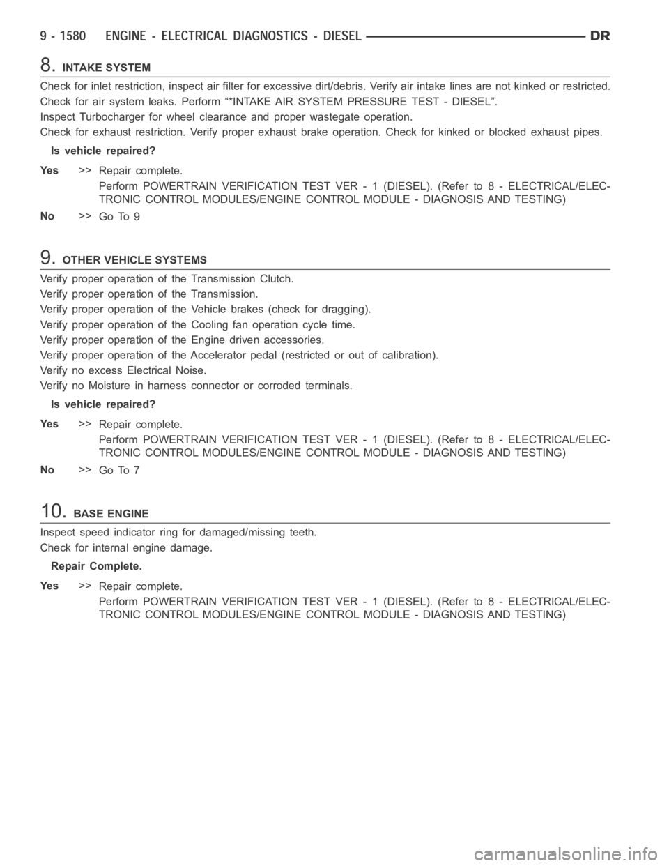
8.INTAKE SYSTEM
Check for inlet restriction, inspect air filter for excessive dirt/debris. Verify air intake lines are not kinked or restricted.
Check for air system leaks. Perform “*INTAKE AIR SYSTEM PRESSURE TEST - DIESEL”.
Inspect Turbocharger for wheel clearance and proper wastegate operation.
Check for exhaust restriction. Verify proper exhaust brake operation. Check for kinked or blocked exhaust pipes.
Is vehicle repaired?
Ye s>>
Repair complete.
Perform POWERTRAIN VERIFICATION TEST VER - 1 (DIESEL). (Refer to 8 - ELECTRICAL/ELEC-
TRONIC CONTROL MODULES/ENGINE CONTROL MODULE - DIAGNOSIS AND TESTING)
No>>
Go To 9
9.OTHER VEHICLE SYSTEMS
Verify proper operation of the Transmission Clutch.
Verify proper operation of the Transmission.
Verify proper operation of the Vehicle brakes (check for dragging).
Verify proper operation of the Cooling fan operation cycle time.
Verify proper operation of the Engine driven accessories.
Verify proper operation of the Accelerator pedal (restricted or out of calibration).
Verify no excess Electrical Noise.
Verify no Moisture in harness connector or corroded terminals.
Is vehicle repaired?
Ye s>>
Repair complete.
Perform POWERTRAIN VERIFICATION TEST VER - 1 (DIESEL). (Refer to 8 - ELECTRICAL/ELEC-
TRONIC CONTROL MODULES/ENGINE CONTROL MODULE - DIAGNOSIS AND TESTING)
No>>
Go To 7
10.BASE ENGINE
Inspect speed indicator ring for damaged/missing teeth.
Check for internal engine damage.
Repair Complete.
Ye s>>
Repair complete.
Perform POWERTRAIN VERIFICATION TEST VER - 1 (DIESEL). (Refer to 8 - ELECTRICAL/ELEC-
TRONIC CONTROL MODULES/ENGINE CONTROL MODULE - DIAGNOSIS AND TESTING)
Page 987 of 5267

Theory of Operation
The engine coolant temperature sensor is a negative temperature coefficient thermistor-type sensor whose resis-
tance varies inversely with temperature. At cold temperatures the sensorresistance is high so the voltage is high.
As the coolant temperature increases the resistance decreases and the voltage becomes low. The INSUFFICIENT
COOLANT TEMP FOR CLOSED-LOOP FUEL CONTROL determines if the engine coolant temperature will reach
theclosedloopfuelingcontroltemperaturelimitinaregulatedtimeafterstart.
When Monitored:
With battery voltage greater than 10.4 volts and after engine is started.
Set Condition:
The engine temperature does not go above -10°C (15°F). Failure time depends on start-up coolant tempera-
ture and ambient temperature. (i.e. 2 minutes for a start temp of -10°C (15°F) or up to 10 minutes for a vehicle
with a start-up temp of -28°C (5°F). Two Trip Fault. Three good trips to turnoff the MIL.
Possible Causes
LOW COOLANT LEVEL
THERMOSTAT
ECT SENSOR
Always perform the Pre-Diagnostic Troubleshooting procedure before proceeding. (Refer to 9 - ENGINE -
DIAGNOSIS AND TESTING).
Diagnostic Test
1.CHECKING COOLANT LEVEL AND CONDITION
Ignition on, engine not running.
With a scan tool, read DTCs.
NOTE: If an Engine Coolant Temperature (ECT) DTC is set along with this code, diagnose the ECT DTC first.
NOTE: Inspect the ECT terminals and related PCM terminals. Make sure the terminals are free from corro-
sion and damage.
NOTE: The best way to diagnose this DTC is to allow the vehicle to sit overnight outside in order to have
a totally cold soaked engine.
NOTE: Extremely cold outside ambient temperatures may have caused this DTCtoset.
WARNING: Never open the cooling system when the engine is hot. The system isunder pressure. Extreme
burns or scalding may result. Failure to follow these instructions can result in personal injury or death.
Allow the engine to cool before opening the cooling system.
Inspect the coolant system for proper level and condition.
Is the coolant level and condition OK?
Ye s>>
Go To 2
No>>
Inspect the vehicle for a coolant leak, make the appropriate repairs, and add the correct amount of
coolant.
Perform the POWERTRAIN VERIFICATION TEST. (Refer to 9 - ENGINE - STANDARD PROCEDURE)
Page 1387 of 5267

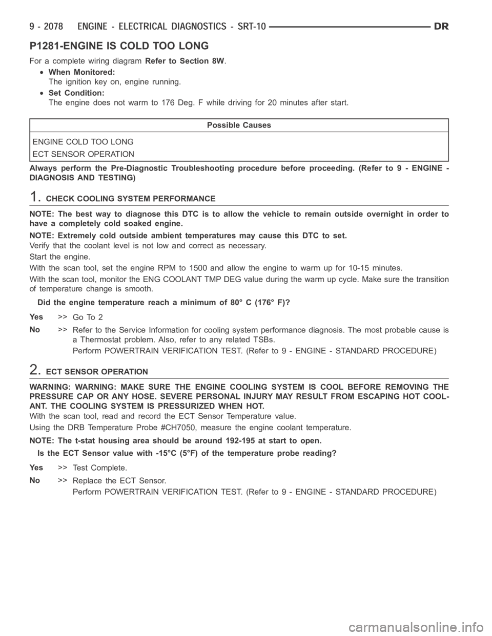
P1281-ENGINE IS COLD TOO LONG
For a complete wiring diagramRefer to Section 8W.
When Monitored:
The ignition key on, engine running.
Set Condition:
The engine does not warm to 176 Deg. F while driving for 20 minutes after start.
Possible Causes
ENGINE COLD TOO LONG
ECT SENSOR OPERATION
Always perform the Pre-Diagnostic Troubleshooting procedure before proceeding. (Refer to 9 - ENGINE -
DIAGNOSIS AND TESTING)
1.CHECK COOLING SYSTEM PERFORMANCE
NOTE: The best way to diagnose this DTC is to allow the vehicle to remain outside overnight in order to
have a completely cold soaked engine.
NOTE: Extremely cold outside ambient temperatures may cause this DTC to set.
Verify that the coolant level is not low and correct as necessary.
Start the engine.
With the scan tool, set the engine RPM to 1500 and allow the engine to warm up for 10-15 minutes.
With the scan tool, monitor the ENG COOLANT TMP DEG value during the warm up cycle. Make sure the transition
of temperature change is smooth.
Did the engine temperature reach a minimum of 80° C (176° F)?
Ye s>>
Go To 2
No>>
Refer to the Service Information for cooling system performance diagnosis. The most probable cause is
a Thermostat problem. Also, refer to any related TSBs.
Perform POWERTRAIN VERIFICATION TEST. (Refer to 9 - ENGINE - STANDARD PROCEDURE)
2.ECT SENSOR OPERATION
WARNING: WARNING: MAKE SURE THE ENGINE COOLING SYSTEM IS COOL BEFORE REMOVING THE
PRESSURE CAP OR ANY HOSE. SEVERE PERSONAL INJURY MAY RESULT FROM ESCAPING HOT COOL-
ANT. THE COOLING SYSTEM IS PRESSURIZED WHEN HOT.
With the scan tool, read and record the ECT Sensor Temperature value.
Using the DRB Temperature Probe #CH7050, measure the engine coolant temperature.
NOTE: The t-stat housing area should be around 192-195 at start to open.
Is the ECT Sensor value with -15°C (5°F) of the temperature probe reading?
Ye s>>
Te s t C o m p l e t e .
No>>
Replace the ECT Sensor.
Perform POWERTRAIN VERIFICATION TEST. (Refer to 9 - ENGINE - STANDARD PROCEDURE)