2006 DODGE RAM SRT-10 tow bar
[x] Cancel search: tow barPage 1765 of 5267

CONDITION POSSIBLE CAUSES CORRECTION
EXCESSIVE OIL CONSUMPTION
OR SPARK PLUGS OIL FOULED1. CCV System malfunction 1. (Refer to 25 - EMISSIONS
CONTROL/EVAPORATIVE
EMISSIONS - DESCRIPTION) for
correct operation
2. Defective valve stem seal(s) 2. Repair or replace seal(s)
3. Worn or broken piston rings 3. Hone cylinder bores. Install new
rings
4. Scuffed pistons/cylinder walls 4. Hone cylinder bores and replace
pistons as required
5. Carbon in oil control ring groove 5. Remove rings and de-carbon
piston
6. Worn valve guides 6. Inspect/replace valve guides as
necessary
7. Piston rings fitted too tightly in
grooves7. Remove rings and check ring end
gap and side clearance. Replace if
necessary
STANDARD PROCEDURE
STANDARD PROCEDURE - REPAIR DAMAGED OR WORN THREADS
CAUTION: Be sure that the tapped holes maintain the original center line.
Damaged or worn threads can be repaired. Essentially, this repair consistsof:
Drilling out worn or damaged threads.
Tapping the hole with a special Heli-Coil Tap, or equivalent.
Installing an insert into the tapped hole to bring the hole back to its original thread size.
STANDARD PROCEDURE—HYDROSTATIC LOCK
CAUTION: DO NOT use the starter motor to rotate the crankshaft. Severe damage could occur.
When an engine is suspected of hydrostatic lock (regardless of what causedthe problem), follow the steps below.
1. Perform the Fuel Pressure Release Procedure (Refer to 14 - FUEL SYSTEM/FUEL DELIVERY - STANDARD
PROCEDURE).
2. Disconnect the negative cable(s) from the battery.
3. Inspect air cleaner, induction system, and intake manifold to ensure system is dry and clear of foreign material.
4. Place a shop towel around the spark plugs to catch any fluid that may possibly be under pressure in the cylinder
head. Remove the spark plugs.
5. With all spark plugs removed, rotate the crankshaft using a breaker bar and socket.
6. Identify the fluid in the cylinders (coolant, fuel, oil, etc.).
7. Be sure all fluid has been removed from the cylinders.
8. Repair engine or components as necessary to prevent this problem from occurring again.
9. Squirt a small amount of engine oil into the cylinders to lubricate the walls. This will prevent damage on restart.
10. Install new spark plugs. Tighten the spark plugs to 41 Nꞏm (30 ft. lbs.) torque.
11. Drain engine oil. Remove and discard the oil filter.
12. Install the drain plug. Tighten the plug to 34 Nꞏm (25 ft. lbs.) torque.
13. Install a new oil filter.
14. Fill engine crankcase with the specified amount and grade of oil. (Refer to LUBRICATION & MAINTENANCE -
SPECIFICATIONS).
Page 1914 of 5267

3. Place a shop towel around the fuel injectors to catch any fluid that may possibly be under pressure in the cyl-
inder head. Remove the fuel injectors (Refer to 14 - FUEL SYSTEM/FUEL INJECTION/FUEL INJECTOR -
REMOVAL).
4. With all injectors removed, rotatethe crankshaft using the crankshaftbarring tool (PN 7471–B).
5. Identify the fluid in the cylinders (coolant, fuel, oil, etc.).
6. Be sure all fluid has been removed from the cylinders.
7. Repair engine or components as necessary to prevent this problem from occurring again.
8. Squirt a small amount of engine oil into the cylinders to lubricate the walls. This will prevent damage on restart.
9. Install fuel injectors (Refer to 14 - FUEL SYSTEM/FUEL INJECTION/FUEL INJECTOR - INSTALLATION).
10. Drain engine oil. Remove and discard the oil filter (Refer to 9 - ENGINE/LUBRICATION/OIL FILTER -
REMOVAL).
11. Installthedrainplug.Tightentheplugto50Nꞏm(37ft.lbs.)torque.
12. Install a new oil filter (Refer to 9 - ENGINE/LUBRICATION/OIL FILTER - INSTALLATION).
13. Fill engine crankcase with the specified amount and grade of oil (Referto LUBRICATION & MAINTENANCE/
FLUID TYPES - SPECIFICATIONS).
14. Connect the negative cable(s) to the battery.
15. Start the engine and check for any leaks.
REMOVAL - ENGINE
1. Disconnect both battery negative cables.
2. Disconnect engine grid heater harness at grid
heater relays.
3. Disconnect electrical connections from rear of alter-
nator.
4. Recover A/C refrigerant. (Refer to 24 - HEATING &
AIR CONDITIONING/PLUMBING - STANDARD
PROCEDURE).
5. Raise vehicle on a hoist.
6. Drain engine coolant (Refer to 7 - COOLING -
STANDARD PROCEDURE).
7. Remove engine oil drain plug and drain engine oil.
8. Reinstall drain plug. Tighten to 50 Nꞏm (37 ft. lbs.)
torque.
9. Lower the vehicle.
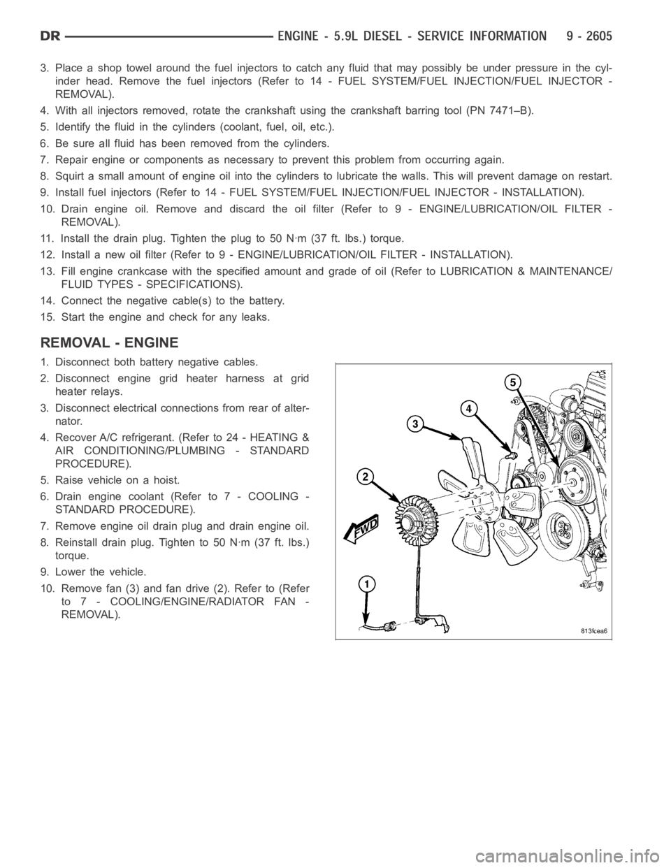
10. Remove fan (3) and fan drive (2). Refer to (Refer
to 7 - COOLING/ENGINE/RADIATOR FAN -
REMOVAL).
Page 1989 of 5267

INSPECTION - CONNECTING ROD
Inspect the connecting rod for damage and wear. The
I-Beam section of the connecting rod cannot have
dents or other damage. Damage to this part can
cause stress risers which will progress to breakage.
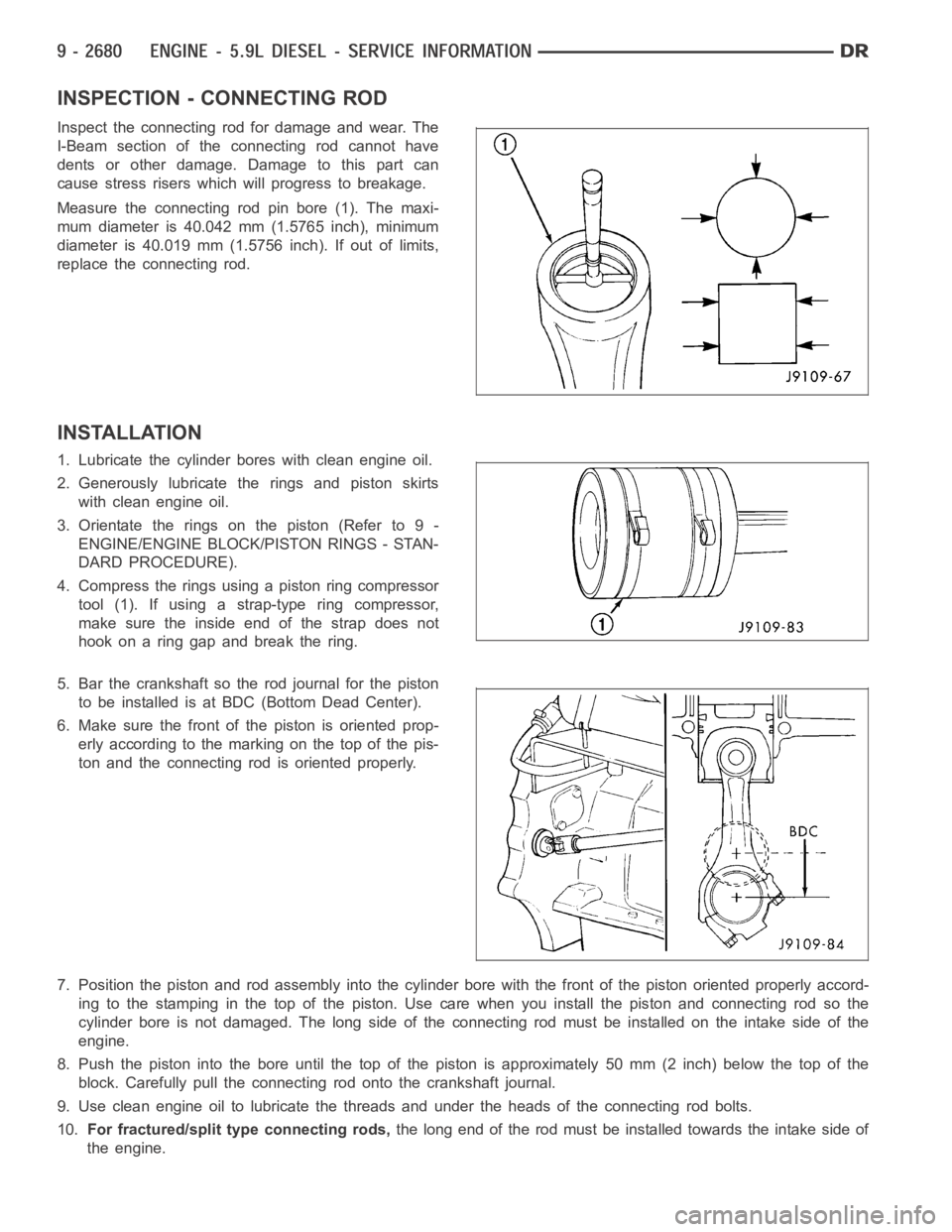
Measure the connecting rod pin bore (1). The maxi-
mum diameter is 40.042 mm (1.5765 inch), minimum
diameter is 40.019 mm (1.5756 inch). If out of limits,
replace the connecting rod.
INSTALLATION
1. Lubricate the cylinder bores with clean engine oil.
2. Generously lubricate the rings and piston skirts
with clean engine oil.
3. Orientate the rings on the piston (Refer to 9 -
ENGINE/ENGINE BLOCK/PISTON RINGS - STAN-
DARD PROCEDURE).
4. Compress the rings using a piston ring compressor
tool(1).Ifusingastrap-typeringcompressor,
make sure the inside end of the strap does not
hook on a ring gap and break the ring.
5. Bar the crankshaft so the rod journal for the piston
to be installed is at BDC(Bottom Dead Center).
6. Make sure the front of the piston is oriented prop-
erly according to the marking on the top of the pis-
ton and the connecting rod is oriented properly.
7. Position the piston and rod assemblyinto the cylinder bore with the front of the piston oriented properly accord-
ing to the stamping in the top of the piston. Use care when you install the piston and connecting rod so the
cylinder bore is not damaged. The long side of the connecting rod must be installed on the intake side of the
engine.
8. Push the piston into the bore until the top of the piston is approximately50 mm (2 inch) below the top of the
block. Carefully pull the connecting rod onto the crankshaft journal.
9. Use clean engine oil to lubricate the threads and under the heads of the connecting rod bolts.
10.For fractured/split type connecting rods,thelongendoftherodmustbeinstalledtowardstheintakesideof
the engine.
Page 2032 of 5267

material also will prevent corrosion. MoparGasket Sealant is available in a 13 oz. aerosol can or 4 oz./16 oz. can
w/applicator.
FORM-IN-PLACE GASKET AND SEALER APPLICATION
MoparGasket Maker material should be applied sparingly 1 mm (0.040 in.) diameter or less of sealant to one
gasket surface. Be certain the material surrounds each mounting hole. Excess material can easily be wiped off.
Components should be torqued in place within 15 minutes. The use of a locating dowel is recommended during
assembly to prevent smearing material off the location.
Mopar
Engine RTV GEN II or ATF RTV gasket material should be applied in a continuous bead approximately 3
mm (0.120 in.) in diameter. All mounting holes must be circled. For corner sealing,a3.17mmor6.35mm(1/8in.
or 1/4 in.) drop is placed in the center of the gasket contact area. Uncured sealant may be removed with a shop
towel. Components should be torqued in place while the sealant is still wettothetouch(within10minutes).The
usage of a locating dowel is recommended during assembly to prevent smearing material off the location.
Mopar
Gasket Sealant in an aerosol can should be applied using a thin, even coat sprayed completely over both
surfaces to be joined, and both sides of a gasket. Then proceed with assembly. Material in a can w/applicator can
be brushed on evenly over the sealing surfaces. Material in an aerosol can shouldbeusedonengineswithmulti-
layer steel gaskets.
ENGINE GASKET SURFACE PREPARATION
To ensure engine gasket sealing, proper surface prep-
aration must be performed, especially with the use of
aluminum engine components and multi-layer steel
cylinder head gaskets.
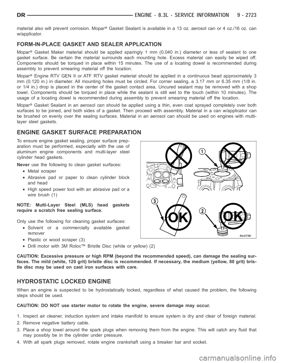
Neveruse the following to clean gasket surfaces:
Metal scraper
Abrasive pad or paper to clean cylinder block
and head
High speed power tool with an abrasive pad or a
wire brush (1)
NOTE: Multi-Layer Steel (MLS) head gaskets
require a scratch free sealing surface.
Only use the following for cleaning gasket surfaces:
Solvent or a commercially available gasket
remover
Plastic or wood scraper (3)
Drill motor with 3M Roloc™ Bristle Disc (white or yellow) (2)
CAUTION: Excessive pressure or high RPM (beyond the recommended speed), can damage the sealing sur-
faces. The mild (white, 120 grit) bristle disc is recommended. If necessary, the medium (yellow, 80 grit) bris-
tle disc may be used on cast iron surfaces with care.
HYDROSTATIC LOCKED ENGINE
When an engine is suspected to be hydrostatically locked, regardless of what caused the problem, the following
steps should be used.
CAUTION: DO NOT use starter motor to rotate the engine, severe damage may occur.
1. Inspect air cleaner, induction system and intake manifold to ensure system is dry and clear of foreign material.
2. Remove negative battery cable.
3. Place a shop towel around the spark plugs when removing them from the engine. This will catch any fluid that
may possibly be in the cylinder under pressure.
4. With all spark plugs removed, rotate engine crankshaft using a breaker bar and socket.