2006 DODGE RAM SRT-10 radiator
[x] Cancel search: radiatorPage 510 of 5267
When Monitored:
While the engine is running.
Set Condition:
The ECM does not read a change in value from the sensor over time.
Possible Causes
LOW COOLANT LEVEL
COOLANT TEMPERATURE SENSOR
THERMOSTAT
INTERMITTENT CONDITION
Always perform the Pre-Diagnostic Troubleshooting procedure before proceeding. (Refer to 9 - ENGINE -
DIAGNOSIS AND TESTING)
Diagnostic Test
1.LOW COOLANT LEVEL
With the engine cold, verify the level of coolant in the radiator.
Is the radiator full of coolant?
Ye s>>
Go To 2
No>>
Fill the radiator with coolant- refer to the owners manual for assistance.
Perform POWERTRAIN VERIFICATION TEST VER - 1 (DIESEL). (Refer to 8 - ELECTRICAL/ELEC-
TRONIC CONTROL MODULES/ENGINE CONTROL MODULE - DIAGNOSIS AND TESTING)
2.COOLANT TEMPERATURE SENSOR
Remove the temperature sensor and reconnect the wiring to the sensor.
Turn the ignition on.
Monitor scan tool, while heating the sensor with an external heat source (DO NOT USE OPEN FLAME).
Does the reading from the sensor increase at least 5 degrees F. on the scan tool?
Ye s>>
Go To 3
No>>
Replace the coolant temp sensor.
Perform POWERTRAIN VERIFICATION TEST VER - 1 (DIESEL). (Refer to 8 - ELECTRICAL/ELEC-
TRONIC CONTROL MODULES/ENGINE CONTROL MODULE - DIAGNOSIS AND TESTING)
3.THERMOSTAT
NOTE: refer to the no trouble code test*Thermostat Testto ensure the thermostat is operating properly.
Is the thermostat operating properly?
Ye s>>
Refer to the INTERMITTENT CONDITION Symptom (Diagnostic Procedure). (Refer to 9 - ENGINE -
DIAGNOSIS AND TESTING)
Perform POWERTRAIN VERIFICATION TEST VER - 1 (DIESEL). (Refer to 8 - ELECTRICAL/ELEC-
TRONIC CONTROL MODULES/ENGINE CONTROL MODULE - DIAGNOSIS AND TESTING)
No>>
Replace the Thermostat.
Perform POWERTRAIN VERIFICATION TEST VER - 1 (DIESEL). (Refer to 8 - ELECTRICAL/ELEC-
TRONIC CONTROL MODULES/ENGINE CONTROL MODULE - DIAGNOSIS AND TESTING)
Page 912 of 5267

P0355-IGNITION COIL #5 PRIMARY
CIRCUIT................................. 1948
P0420-1/1 CATALYTIC CONVERTER
EFFICIENCY............................. 1952
P0432-2/1 CATALYTIC CONVERTER
EFFICIENCY............................. 1955
P0441-EVAP PURGE FLOW MONITOR . . . . . 1958
P0442-EVAP LEAK MONITOR MEDIUM
(0.040) LEAK DETECTED.................. 1962
P0443-EVAP PURGE SOLENOID CIRCUIT . . 1968
P0455-EVAP LEAK MONITOR LARGE LEAK
DETECTED............................... 1972
P0460-FUEL LEVEL SENDING UNIT NO
CHANGE OVER MILES.................... 1978
P0462-FUEL LEVEL SENDING UNIT VOLTS
TOO LOW................................ 1979
P0463-FUEL LEVEL SENSOR 1 CIRCUIT
HIGH.................................... 1982
P0500-NO VEHICLE SPEED SIGNAL ....... 1986
P0505-IDLE AIR CONTROL MOTOR
CIRCUITS................................ 1989
P0513-INVALID SKREEM KEY ............. 1994
P0522-OIL PRESSURE CIRCUIT LOW ...... 1996
P0523-OIL PRESSURE CIRCUIT HIGH ..... 2000
P0601-PCM INTERNAL CONTROLLER
FAILURE................................. 2003
P0622-GENERATOR FIELD NOT
SWITCHING PROPERLY.................. 2004
P0645-A/C CLUTCH RELAY CIRCUIT . . ..... 2008
P0801-REVERSE GEAR LOCKOUT CIRCUIT
OPEN OR SHORTED...................... 2012
P1195-O2 SENSOR 1/1 SLOW DURING
CATALYST MONITOR..................... 2016
P1196-O2 SENSOR 2/1 SLOW DURING
CATALYST MONITOR..................... 2019
P126B-ASD CONTROL CIRCUIT 2 LOW .... 2022
P126C-ASD CONTROL CIRCUIT 2 HIGH .... 2026
P126D-ASD CONTROL CIRCUIT 2 OPEN . . . 2030
P126E-ASD CONTROL CIRCUIT
OVERCURRENT.......................... 2034
P1272-A/C CLUTCH CONTROL CIRCUIT 2
LOW..................................... 2038
P1273-A/C CLUTCH CONTROL CIRCUIT 2
HIGH.................................... 2041
P1274-A/C CLUTCH CONTROL CIRCUIT 2
OPEN.................................... 2045
P1275-A/C CLUTCH CONTROL CIRCUIT 2
OVERCURRENT.......................... 2049
P1277-STARTER CONTROL CIRCUIT 2 LOW
(TIPM)................................... 2052
P1278-STARTER CONTROL CIRCUIT 2
HIGH (TIPM).............................. 2055
P1279-STARTER CONTROL CIRCUIT 2
OPEN (TIPM)............................. 2058
P127A-STARTER CONTROL CIRCUIT 2
OVERCURRENT.......................... 2061
P127C-FUEL PUMP CONTROL CIRCUIT 2
LOW..................................... 2064P127D-FUEL PUMP CONTROL CIRCUIT 2
HIGH.................................... 2067
P127E-FUEL PUMP CONTROL CIRCUIT 2
OPEN (TIPM)............................. 2071
P0127F-FUEL PUMP CONTROL CIRCUIT 2
OVERCURRENT (TIPM)................... 2075
P1281-ENGINE IS COLD TOO LONG ....... 2078
P1282-FUEL PUMP/SYSTEM RELAY
CONTROL CIRCUIT....................... 2079
P1294-TARGET IDLE NOT REACHED ...... 2082
P1296-NO 5-VOLTS TO MAP SENSOR ..... 2085
P1297-NO CHANGE IN MAP FROM START
TO RUN.................................. 2089
P1388-AUTO SHUTDOWN RELAY CONTROL
CIRCUIT................................. 2094
P1389-NO ASD RELAY OUTPUT VOLTAGE
AT P C M.................................. 2097
P1391-INTERMITTENT LOSS OF CMP OR
CKP
..................................... 2100
P1398-MIS-FIRE ADAPTIVE NUMERATOR
AT L I M I T................................. 2104
P1486-EVAP LEAK MONITOR PINCHED
HOSE FOUND............................ 2106
P1492-AMBIENT/BATTERY TEMPERATURE
SENSOR VOLTAGE TOO HIGH............. 2110
P1493-AMBIENT/BATTERY TEMPERATURE
SENSOR VOLTAGE TOO LOW............. 2114
P1494-LEAK DETECTION PUMP SWITCH
OR MECHANICAL FAULT.................. 2117
P1495-LEAK DETECTION PUMP SOLENOID
CIRCUIT................................. 2121
P1499-HYDRAULIC FAN SOLENOID
CIRCUIT................................. 2126
P1594-CHARGING SYSTEM VOLTAGE TOO
HIGH.................................... 2130
P1598-A/C PRESSURE SENSOR VOLTAGE
TOO HIGH............................... 2133
P1599-A/C PRESSURE SENSOR VOLTAGE
TOO LOW................................ 2137
P1682-CHARGING SYSTEM VOLTAGE TOO
LOW..................................... 2141
P1687-NO CLUSTER BUS MESSAGE ...... 2146
P1695-BUS MESSAGE FROM BODY
CONTROL MODULE...................... 2148
P1696-PCM FAILURE EEPROM WRITE
DENIED.................................. 2151
*BRAKE SWITCH SENSE STATUS DOES
NOT CHANGE ON THE SCAN TOOL....... 2153
*CANNOT SHIFT INTO REVERSE .......... 2157
*CHECKING A/C SYSTEM OPERATION
WITH NO DTCS.......................... 2159
*CHECKING CHARGING SYSTEM
OPERATION WITH NO DTCS.............. 2163
*CHECKING RADIATOR FAN OPERATION . . 2167
*CHECKING THE PCM POWER AND
GROUNDS............................... 2169
B2277–CAN GATEWAY INTERNAL
(GATEWAY).............................. 2172
U0001–CAN C BUS CIRCUIT (GATEWAY) . . . 2172
Page 1436 of 5267
When Monitored:
Ignition on and engine running.
Set Condition:
An open or shorted condition in the Hydraulic Fan Solenoid control circuitis detected by the Powertrain Control
Module.
Possible Causes
RADIATOR FAN INOP
(K342) FUSED ASD RELAY OUTPUT CIRCUIT
(C240) COOLING FAN CONTROL CIRCUIT OPEN
(C240) COOLING FAN CONTROL CIRCUIT SHORTED TO GROUND
HYDRAULIC FAN
PCM
Always perform the Pre-Diagnostic Troubleshooting procedure before proceeding. (Refer to 9 - ENGINE -
DIAGNOSIS AND TESTING)
1.RADIATOR FAN INOP
Ignition on, engine not running.
With the scan tool, perform the Hydraulic Fan Solenoid Test found under Engine Test and Systems Test.
Does the Radiator Fan operate properly?
Ye s>>
Refer to the INTERMITTENT CONDITIONSymptom (Diagnostic Procedure).
Perform POWERTRAIN VERIFICATION TEST. (Refer to 9 - ENGINE - STANDARD PROCEDURE)
No>>
Go To 2
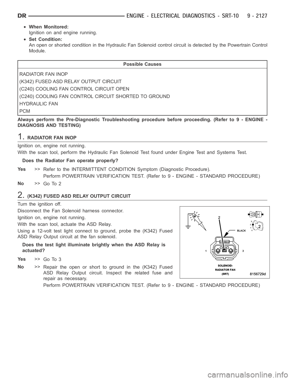
2.(K342) FUSED ASD RELAY OUTPUT CIRCUIT
Turn the ignition off.
Disconnect the Fan Solenoid harness connector.
Ignition on, engine not running.
With the scan tool, actuate the ASD Relay.
Using a 12-volt test light connect to ground, probe the (K342) Fused
ASD Relay Output circuit at the fan solenoid.
Does the test light illuminate brightly when the ASD Relay is
actuated?
Ye s>>
Go To 3
No>>
Repair the open or short to ground in the (K342) Fused
ASD Relay Output circuit. Inspect the related fuse and
repair as necessary.
Perform POWERTRAIN VERIFICATION TEST. (Refer to 9 - ENGINE - STANDARD PROCEDURE)
Page 1437 of 5267
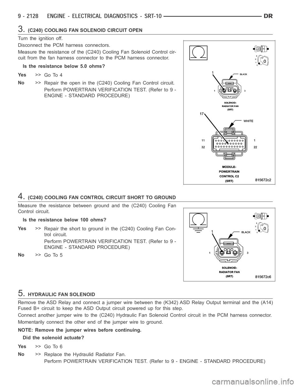
3.(C240) COOLING FAN SOLENOID CIRCUIT OPEN
Turn the ignition off.
Disconnect the PCM harness connectors.
Measure the resistance of the (C240) Cooling Fan Solenoid Control cir-
cuit from the fan harness connector to the PCM harness connector.
Is the resistance below 5.0 ohms?
Ye s>>
Go To 4
No>>
Repair the open in the (C240) Cooling Fan Control circuit.
Perform POWERTRAIN VERIFICATION TEST. (Refer to 9 -
ENGINE - STANDARD PROCEDURE)
4.(C240) COOLING FAN CONTROL CIRCUIT SHORT TO GROUND
Measure the resistance between ground and the (C240) Cooling Fan
Control circuit.
Istheresistancebelow100ohms?
Ye s>>
Repair the short to ground in the (C240) Cooling Fan Con-
trol circuit.
Perform POWERTRAIN VERIFICATION TEST. (Refer to 9 -
ENGINE - STANDARD PROCEDURE)
No>>
Go To 5
5.HYDRAULIC FAN SOLENOID
Remove the ASD Relay and connect a jumper wire between the (K342) ASD Relay Output terminal and the (A14)
Fused B+ circuit to keep the ASD Output circuit powered up for this step.
Connect another jumper wire to the (C240) Hydraulic Fan Solenoid Control circuit in the PCM harness connector.
Momentarily connect the other end of the jumper wire to ground.
NOTE: Remove the jumper wires before continuing.
Did the solenoid actuate?
Ye s>>
Go To 6
No>>
Replace the Hydraulid Radiator Fan.
Perform POWERTRAIN VERIFICATION TEST. (Refer to 9 - ENGINE - STANDARD PROCEDURE)
Page 1476 of 5267
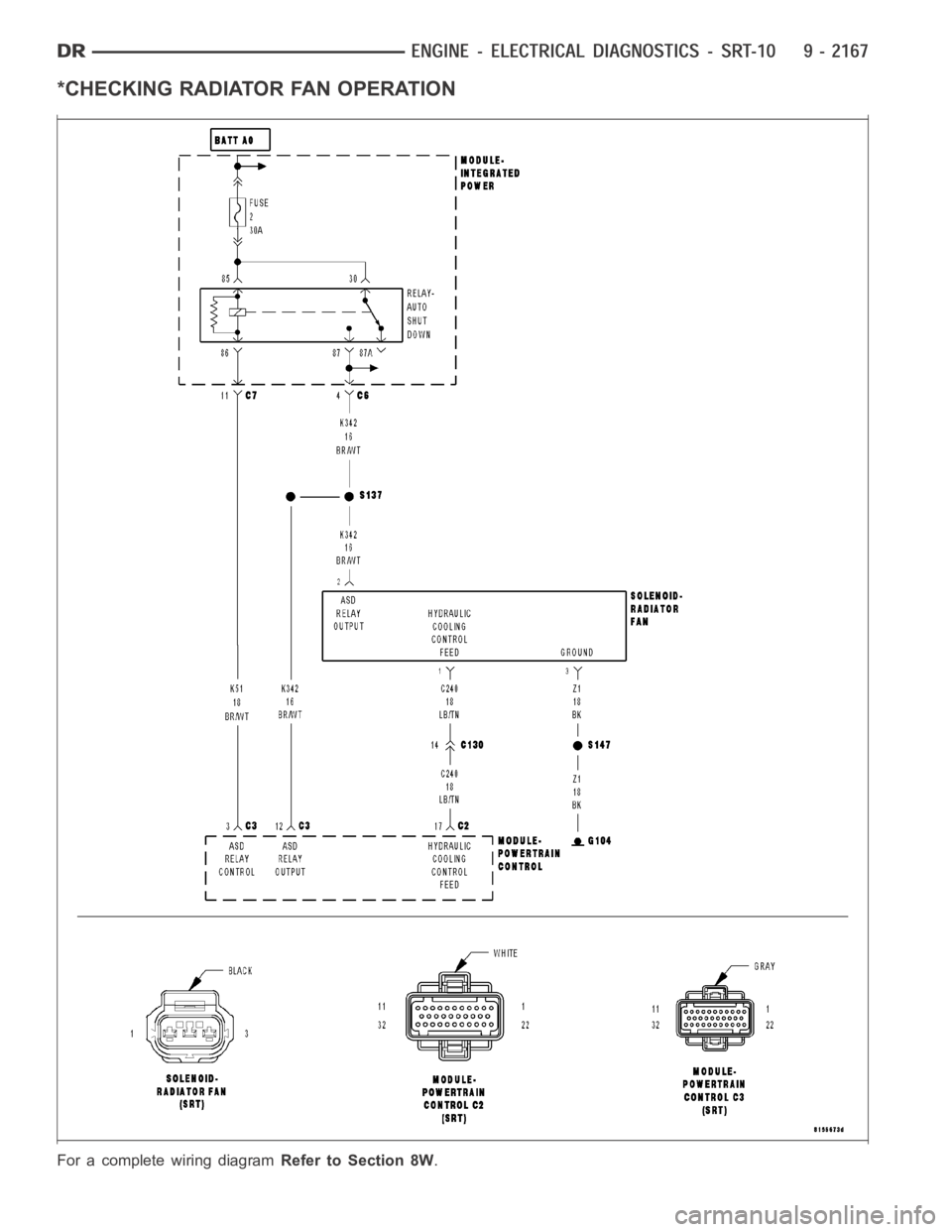
*CHECKING RADIATOR FAN OPERATION
For a complete wiring diagramRefer to Section 8W.
Page 1494 of 5267
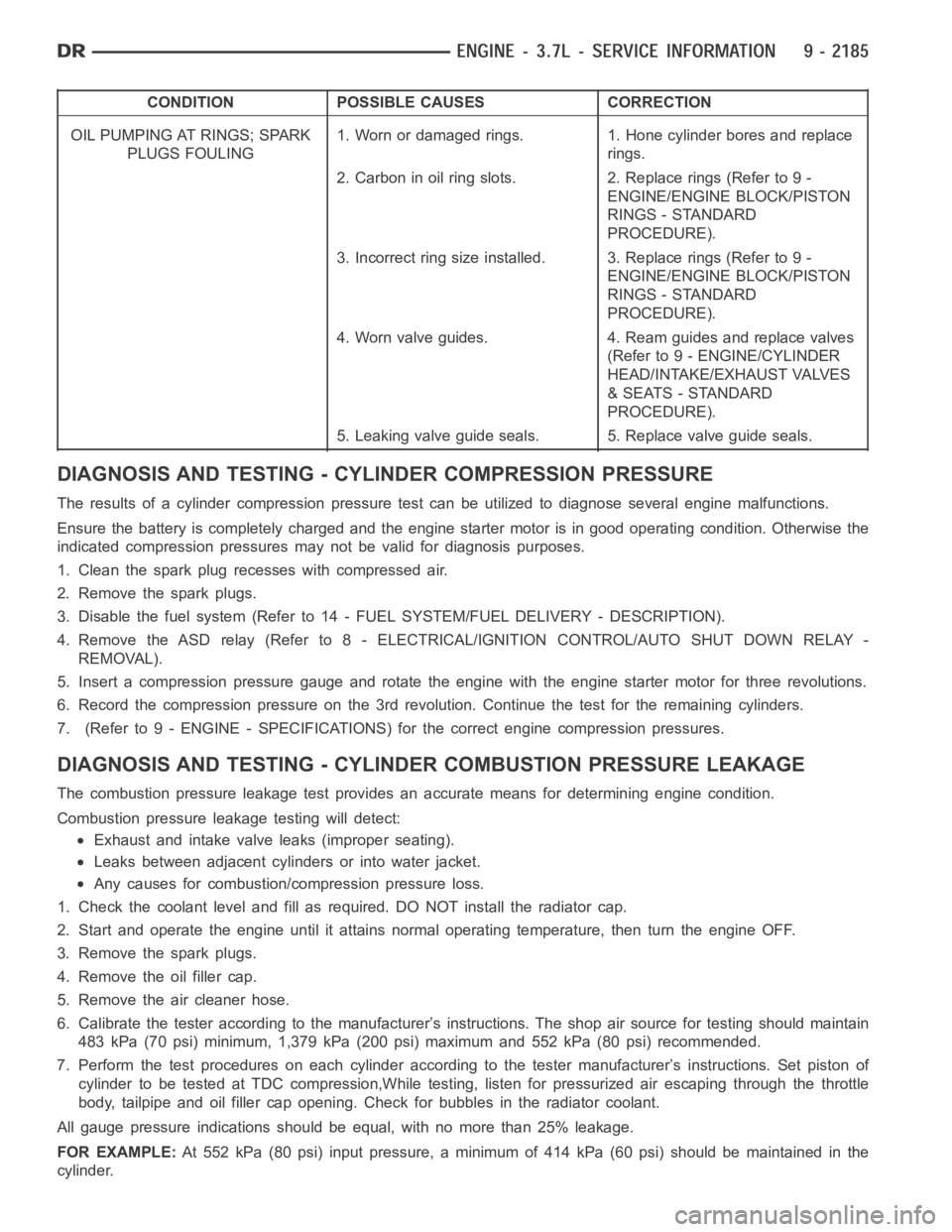
CONDITION POSSIBLE CAUSES CORRECTION
OIL PUMPING AT RINGS; SPARK
PLUGS FOULING1. Worn or damaged rings. 1. Hone cylinder bores and replace
rings.
2. Carbon in oil ring slots. 2. Replace rings (Refer to 9 -
ENGINE/ENGINE BLOCK/PISTON
RINGS - STANDARD
PROCEDURE).
3. Incorrect ring size installed. 3. Replace rings (Refer to 9 -
ENGINE/ENGINE BLOCK/PISTON
RINGS - STANDARD
PROCEDURE).
4. Worn valve guides. 4. Ream guides and replace valves
(Refer to 9 - ENGINE/CYLINDER
HEAD/INTAKE/EXHAUST VALVES
& SEATS - STANDARD
PROCEDURE).
5. Leaking valve guide seals. 5. Replace valve guide seals.
DIAGNOSIS AND TESTING - CYLINDER COMPRESSION PRESSURE
The results of a cylinder compressionpressure test can be utilized to diagnose several engine malfunctions.
Ensurethebatteryiscompletelychargedandtheenginestartermotorisingood operating condition. Otherwise the
indicated compression pressures may not be valid for diagnosis purposes.
1. Clean the spark plug recesses with compressed air.
2. Remove the spark plugs.
3. Disable the fuel system (Refer to 14 - FUEL SYSTEM/FUEL DELIVERY - DESCRIPTION).
4. Remove the ASD relay (Refer to 8 - ELECTRICAL/IGNITION CONTROL/AUTO SHUTDOWNRELAY-
REMOVAL).
5. Insert a compression pressure gauge and rotate the engine with the engine starter motor for three revolutions.
6. Record the compression pressure on the 3rd revolution. Continue the test for the remaining cylinders.
7. (Refer to 9 - ENGINE - SPECIFICATIONS) for the correct engine compression pressures.
DIAGNOSIS AND TESTING - CYLINDERCOMBUSTION PRESSURE LEAKAGE
The combustion pressure leakage test provides an accurate means for determining engine condition.
Combustion pressure leakage testing will detect:
Exhaust and intake valve leaks (improper seating).
Leaks between adjacent cylinders or into water jacket.
Any causes for combustion/compression pressure loss.
1. Check the coolant level and fill as required. DO NOT install the radiatorcap.
2. Start and operate the engine until it attains normal operating temperature, then turn the engine OFF.
3. Remove the spark plugs.
4. Remove the oil filler cap.
5. Remove the air cleaner hose.
6. Calibrate the tester according to the manufacturer’s instructions. The shop air source for testing should maintain
483 kPa (70 psi) minimum, 1,379 kPa (200 psi) maximum and 552 kPa (80 psi) recommended.
7. Perform the test procedures on each cylinder according to the tester manufacturer’s instructions. Set piston of
cylinder to be tested at TDC compression,While testing, listen for pressurized air escaping through the throttle
body, tailpipe and oil filler cap opening. Check for bubbles in the radiator coolant.
All gauge pressure indications should be equal, with no more than 25% leakage.
FOR EXAMPLE:At 552 kPa (80 psi) input pressure, a minimum of 414 kPa (60 psi) should be maintained in the
cylinder.
Page 1495 of 5267
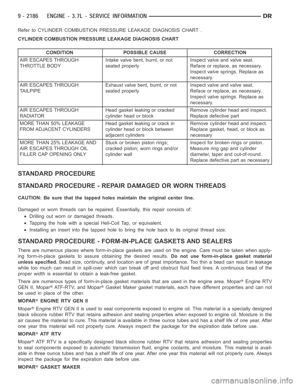
Refer to CYLINDER COMBUSTION PRESSURE LEAKAGE DIAGNOSIS CHART .
CYLINDER COMBUSTION PRESSURE LEAKAGE DIAGNOSIS CHART
CONDITION POSSIBLE CAUSE CORRECTION
AIR ESCAPES THROUGH
THROTTLE BODYIntake valve bent, burnt, or not
seated properlyInspect valve and valve seat.
Reface or replace, as necessary.
Inspect valve springs. Replace as
necessary.
AIR ESCAPES THROUGH
TAILPIPEExhaust valve bent, burnt, or not
seated properlyInspect valve and valve seat.
Reface or replace, as necessary.
Inspect valve springs. Replace as
necessary.
AIR ESCAPES THROUGH
RADIATORHead gasket leaking or cracked
cylinder head or blockRemove cylinder head and inspect.
Replace defective part
MORE THAN 50% LEAKAGE
FROM ADJACENT CYLINDERSHead gasket leaking or crack in
cylinder head or block between
adjacent cylindersRemove cylinder head and inspect.
Replace gasket, head, or block as
necessary
MORE THAN 25% LEAKAGE AND
AIR ESCAPES THROUGH OIL
FILLER CAP OPENING ONLYStuckorbrokenpistonrings;
cracked piston; worn rings and/or
cylinder wallInspect for broken rings or piston.
Measure ring gap and cylinder
diameter, taper and out-of-round.
Replace defective part as necessary
STANDARD PROCEDURE
STANDARD PROCEDURE - REPAIR DAMAGED OR WORN THREADS
CAUTION: Be sure that the tapped holes maintain the original center line.
Damaged or worn threads can be repaired. Essentially, this repair consistsof:
Drilling out worn or damaged threads.
Tapping the hole with a special Heli-Coil Tap, or equivalent.
Installing an insert into the tapped hole to bring the hole back to its original thread size.
STANDARD PROCEDURE - FORM-IN-PLACE GASKETS AND SEALERS
There are numerous places where form-in-place gaskets are used on the engine. Care must be taken when apply-
ing form-in-place gaskets to assure obtaining the desired results.Do not use form-in-place gasket material
unless specified.Bead size, continuity, and location are of great importance. Too thin a bead can result in leakage
while too much can result in spill-overwhich can break off and obstruct fluid feed lines. A continuous bead of the
proper width is essential to obtain a leak-free gasket.
There are numerous types of form-in-place gasket materials that are used in the engine area. Mopar
Engine RTV
GEN II, Mopar
ATF-RTV, and MoparGasket Maker gasket materials, each have different properties and can not
be used in place of the other.
MOPAR
ENGINE RTV GEN II
Mopar
Engine RTV GEN II is used to seal components exposed to engine oil. This material is a specially designed
black silicone rubber RTV that retains adhesion and sealing properties when exposed to engine oil. Moisture in the
air causes the material to cure. This material is available in three ounce tubes and has a shelf life of one year. After
one year this material will not properly cure. Always inspect the package for the expiration date before use.
MOPAR
AT F R T V
Mopar
ATF RTV is a specifically designed black silicone rubber RTV that retains adhesion and sealing properties
to seal components exposed to automatic transmission fluid, engine coolants, and moisture. This material is avail-
able in three ounce tubes and has a shelf life of one year. After one year thismaterial will not properly cure. Always
inspect the package for the expiration date before use.
MOPAR
GASKET MAKER
Page 1497 of 5267
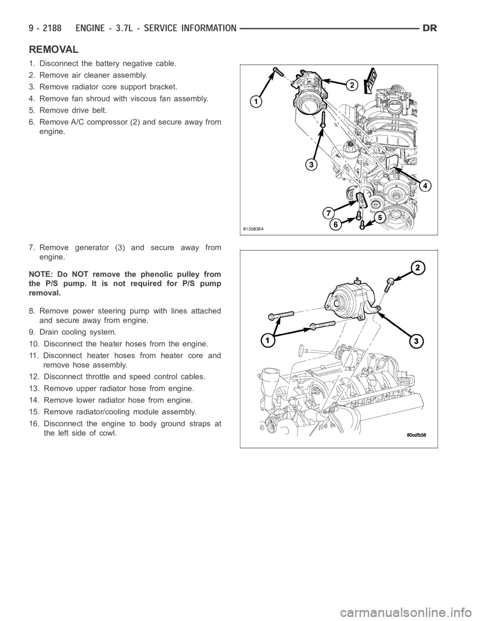
REMOVAL
1. Disconnect the battery negative cable.
2. Remove air cleaner assembly.
3. Remove radiator core support bracket.
4. Remove fan shroud with viscous fan assembly.
5. Remove drive belt.
6. Remove A/C compressor (2) and secure away from
engine.
7. Remove generator (3) and secure away from
engine.
NOTE: Do NOT remove the phenolic pulley from
the P/S pump. It is not required for P/S pump
removal.
8. Remove power steering pump with lines attached
and secure away from engine.
9. Drain cooling system.
10. Disconnect the heater hoses from the engine.
11. Disconnect heater hoses from heater core and
remove hose assembly.
12. Disconnect throttle and speed control cables.
13. Remove upper radiator hose from engine.
14. Remove lower radiator hose from engine.
15. Remove radiator/cooling module assembly.
16. Disconnect the engine to body ground straps at
theleftsideofcowl.