2006 DODGE RAM SRT-10 airbag disable
[x] Cancel search: airbag disablePage 2421 of 5267
REMOVAL
SERVICE PRECAUTIONS
NOTE: The steering column on vehicles equipped with an automatic transmission is not equipped with an
internal locking shaft with the ignition cylinder. Alternative methods of locking the steering wheel for ser-
vice will have to be used.
To service the steering wheel, switches or airbag, Refer to Electrical Restraints and follow all WARNINGS and CAU-
TIONS.
WARNING: The airbag system is a sensitive, complex electro-mechanical unit. Before attempting to diag-
nose, remove or install the airbag system components you must first disconnect and isolate the battery
negative (ground) cable. Then wait two minutes for the system capacitor todischarge. Failure to do so
could result in accidental deployment of the airbag and possible personalinjury. The fasteners, screws, and
bolts, originally used for the airbag components, have special coatings and are specifically designed for the
airbag system. They must never be replaced with any substitutes. Anytime anew fastener is needed,
replace with the correct fasteners provided in the service package or fasteners listed in the parts books.
CAUTION: Do not hammer on steering column shaft. This may cause damage to the shaft or bearing.
CAUTION: Do not attempt to remove the pivot bolts to disassemble the tilting mechanism.
The ignition key must be in the key cylinder for cylinder removal. The key cylinder must be removed first before
removing ignition switch.
1. Remove the negative (ground) cable from the battery.
2. Disable the airbag, (Refer to 8 - ELECTRICAL/RESTRAINTS/DRIVER AIRBAG- REMOVAL).
3. Remove the kneeblocker and steering column reinforcement panel.
4. Remove the lower and upper shrouds.
5. Remove key cylinder. (Refer to 19 - STEERING/COLUMN/LOCK CYLINDER HOUSING - REMOVAL).
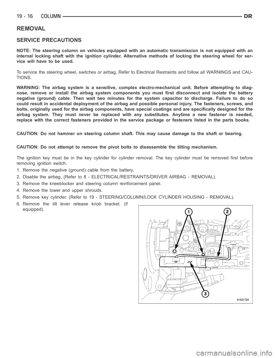
6. Remove the tilt lever release knob bracket. (if
equipped).
Page 2429 of 5267
STEERING WHEEL
REMOVAL
1. Disable and remove the driver’s side airbag. (Refer
to 8 - ELECTRICAL/RESTRAINTS/DRIVER AIR-
BAG - REMOVAL).
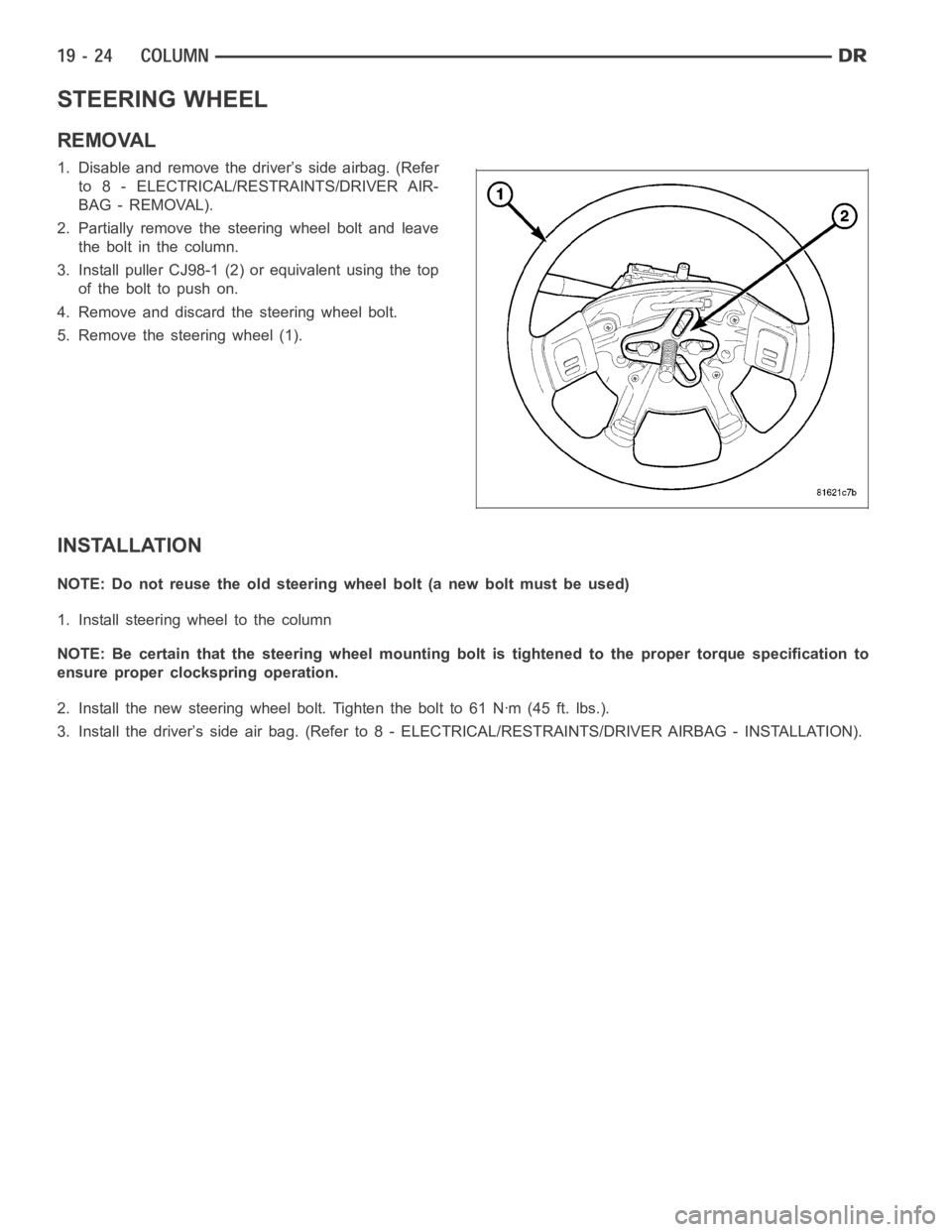
2. Partially remove the steering wheel bolt and leave
theboltinthecolumn.
3. Install puller CJ98-1 (2) or equivalent using the top
ofthebolttopushon.
4. Remove and discard the steering wheel bolt.
5. Remove the steering wheel (1).
INSTALLATION
NOTE: Do not reuse the old steering wheel bolt (a new bolt must be used)
1. Install steering wheel to the column
NOTE: Be certain that the steering wheel mounting bolt is tightened to the proper torque specification to
ensure proper clockspring operation.
2. Install the new steering wheel bolt. Tighten the bolt to 61 Nꞏm (45 ft. lbs.).
3. Install the driver’s side air bag. (Refer to 8 - ELECTRICAL/RESTRAINTS/DRIVER AIRBAG - INSTALLATION).
Page 4476 of 5267
CLUSTER BEZEL
REMOVAL
WARNING: On vehicles equipped with airbags, disable the airbag system before attempting any steering
wheel, steering column, seat belt tensioner, or instrument panel component diagnosis or service. Discon-
nect and isolate the battery negative (ground) cable, then wait two minutes for the airbag system capacitor
to discharge before performing further diagnosis or service. This is the only sure way to disable the airbag
system. Failure to take the proper precautions could result in accidentalairbag deployment and possible
personal injury or death.
1. Disconnect and isolate the negative battery cable.
2. Remove the steering column opening cover. (Refer
to 23 - BODY/INSTRUMENT PANEL/STEERING
COLUMN OPENING COVER - REMOVAL)
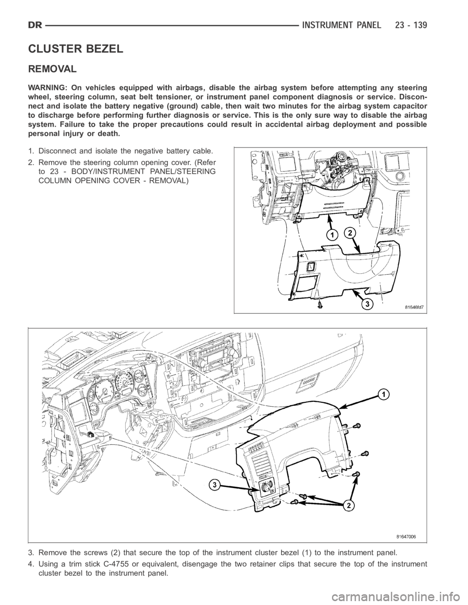
3. Remove the screws (2) that secure the top of the instrument cluster bezel(1) to the instrument panel.
4. Using a trim stick C-4755 or equivalent, disengage the two retainer clips that secure the top of the instrument
cluster bezel to the instrument panel.
Page 4484 of 5267
INSTRUMENT PANEL ASSEMBLY
REMOVAL
WARNING: On vehicles equipped with airbags, disable the airbag system before attempting any steering
wheel, steering column, seat belt tensioner, or instrument panel component diagnosis or service. Discon-
nect and isolate the battery negative (ground) cable, then wait two minutes for the airbag system capacitor
to discharge before performing further diagnosis or service. This is the only sure way to disable the airbag
system. Failure to take the proper precautions could result in accidentalairbag deployment and possible
personal injury or death.
1. Disconnect and isolate the negative battery cable.
2. Remove the left a-pillar trim (Refer to 23 - BODY/
INTERIOR/A-PILLAR TRIM/GRAB HANDLE -
REMOVAL).
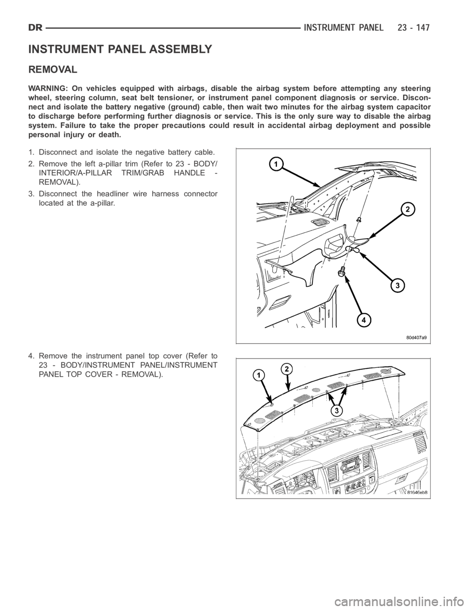
3. Disconnect the headliner wire harness connector
located at the a-pillar.
4. Remove the instrument panel top cover (Refer to
23 - BODY/INSTRUMENT PANEL/INSTRUMENT
PANEL TOP COVER - REMOVAL).
Page 4501 of 5267
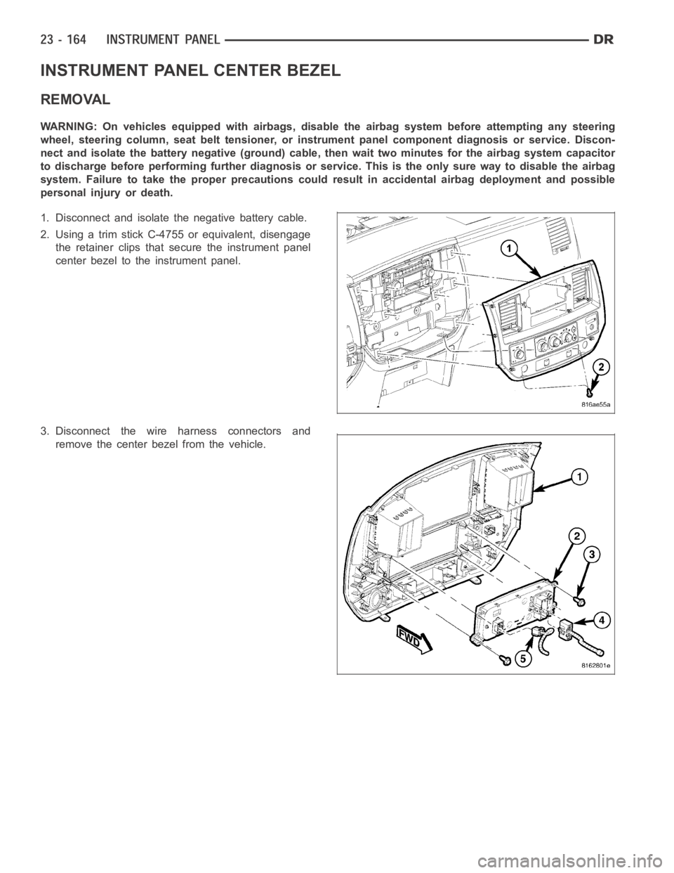
INSTRUMENT PANEL CENTER BEZEL
REMOVAL
WARNING: On vehicles equipped with airbags, disable the airbag system before attempting any steering
wheel, steering column, seat belt tensioner, or instrument panel component diagnosis or service. Discon-
nect and isolate the battery negative (ground) cable, then wait two minutes for the airbag system capacitor
to discharge before performing further diagnosis or service. This is the only sure way to disable the airbag
system. Failure to take the proper precautions could result in accidentalairbag deployment and possible
personal injury or death.
1. Disconnect and isolate the negative battery cable.
2. Using a trim stick C-4755 or equivalent, disengage
the retainer clips that secure the instrument panel
center bezel to the instrument panel.
3. Disconnect the wire harness connectors and
remove the center bezel from the vehicle.
Page 4503 of 5267
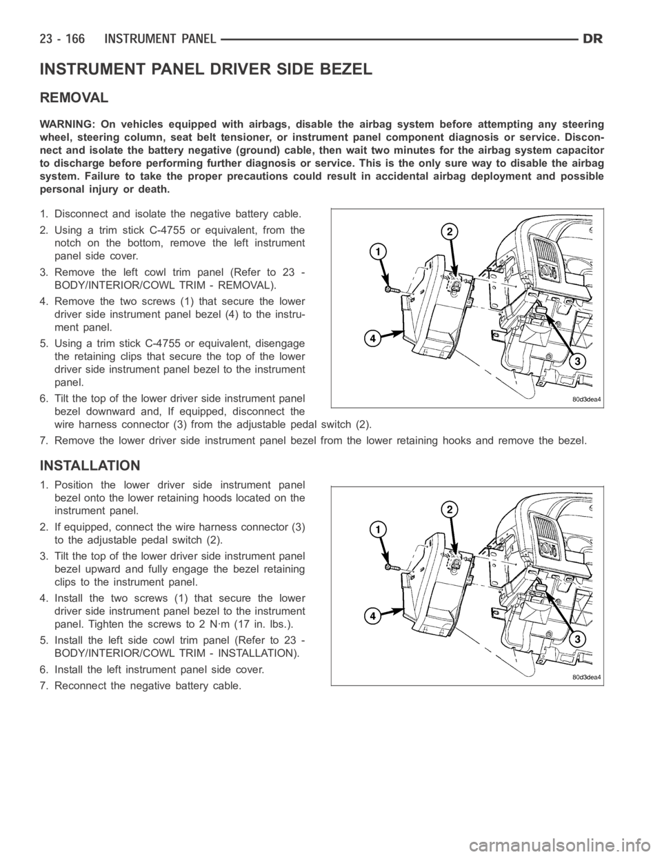
INSTRUMENT PANEL DRIVER SIDE BEZEL
REMOVAL
WARNING: On vehicles equipped with airbags, disable the airbag system before attempting any steering
wheel, steering column, seat belt tensioner, or instrument panel component diagnosis or service. Discon-
nect and isolate the battery negative (ground) cable, then wait two minutes for the airbag system capacitor
to discharge before performing further diagnosis or service. This is the only sure way to disable the airbag
system. Failure to take the proper precautions could result in accidentalairbag deployment and possible
personal injury or death.
1. Disconnect and isolate the negative battery cable.
2. Using a trim stick C-4755 or equivalent, from the
notch on the bottom, remove the left instrument
panel side cover.
3. Remove the left cowl trim panel (Refer to 23 -
BODY/INTERIOR/COWL TRIM - REMOVAL).
4. Remove the two screws (1) that secure the lower
driver side instrument panel bezel (4) to the instru-
ment panel.
5. Using a trim stick C-4755 or equivalent, disengage
the retaining clips that secure the top of the lower
driver side instrument panel bezel to the instrument
panel.
6. Tilt the top of the lower driver side instrument panel
bezel downward and, If equipped, disconnect the
wire harness connector (3) from the adjustable pedal switch (2).
7. Remove the lower driver side instrument panel bezel from the lower retaining hooks and remove the bezel.
INSTALLATION
1. Position the lower driver side instrument panel
bezel onto the lower retaining hoods located on the
instrument panel.
2. If equipped, connect the wire harness connector (3)
to the adjustable pedal switch (2).
3. Tilt the top of the lower driver side instrument panel
bezel upward and fully engage the bezel retaining
clips to the instrument panel.
4. Install the two screws (1) that secure the lower
driver side instrument panel bezel to the instrument
panel. Tighten the screws to 2 Nꞏm (17 in. lbs.).
5. Install the left side cowl trim panel (Refer to 23 -
BODY/INTERIOR/COWL TRIM - INSTALLATION).
6. Install the left instrument panel side cover.
7. Reconnect the negative battery cable.
Page 4504 of 5267
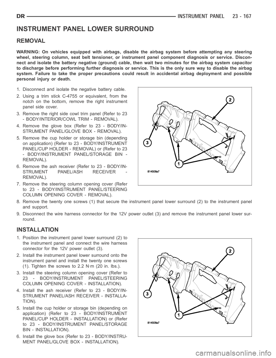
INSTRUMENT PANEL LOWER SURROUND
REMOVAL
WARNING: On vehicles equipped with airbags, disable the airbag system before attempting any steering
wheel, steering column, seat belt tensioner, or instrument panel component diagnosis or service. Discon-
nect and isolate the battery negative (ground) cable, then wait two minutes for the airbag system capacitor
to discharge before performing further diagnosis or service. This is the only sure way to disable the airbag
system. Failure to take the proper precautions could result in accidentalairbag deployment and possible
personal injury or death.
1. Disconnect and isolate the negative battery cable.
2. Using a trim stick C-4755 or equivalent, from the
notch on the bottom, remove the right instrument
panel side cover.
3. Remove the right side cowl trim panel (Refer to 23
- BODY/INTERIOR/COWL TRIM - REMOVAL).
4. Remove the glove box (Refer to 23 - BODY/IN-
STRUMENT PANEL/GLOVE BOX - REMOVAL).
5. Remove the cup holder or storage bin (depending
on application) (Refer to 23 - BODY/INSTRUMENT
PANEL/CUPHOLDER-REMOVAL)or(Referto23
- BODY/INSTRUMENT PANEL/STORAGE BIN -
REMOVAL).
6. Remove the ash receiver (Refer to 23 - BODY/IN-
STRUMENT PANEL/ASH RECEIVER -
REMOVAL).
7. Remove the steering column opening cover (Refer
to 23 - BODY/INSTRUMENT PANEL/STEERING
COLUMN OPENING COVER - REMOVAL).
8. Remove the twenty one screws (1) that secure the instrument panel lower surround (2) to the instrument panel
and support.
9. Disconnect the wire harness connector for the 12V power outlet (3) and remove the instrument panel lower sur-
round.
INSTALLATION
1. Position the instrument panel lower surround (2) to
the instrument panel and connect the wire harness
connector for the 12V power outlet (3).
2. Install the instrument panel lower surround onto the
instrument panel and install the twenty one screws
(1). Tighten the screws to 2.2 Nꞏm (20 in. lbs.).
3. Install the steering column opening cover (Refer to
23 - BODY/INSTRUMENT PANEL/STEERING
COLUMN OPENING COVER - INSTALLATION).
4. Install the ash receiver (Refer to 23 - BODY/IN-
STRUMENT PANEL/ASH RECEIVER - INSTALLA-
TION).
5. Install the cup holder or storage bin (depending on
application) (Refer to 23 - BODY/INSTRUMENT
PANEL/CUP HOLDER - INSTALLATION) or (Refer
to 23 - BODY/INSTRUMENT PANEL/STORAGE
BIN - INSTALLATION).
6. Install the glove box (Refer to 23 - BODY/INSTRU-
MENT PANEL/GLOVE BOX - INSTALLATION).
Page 4512 of 5267
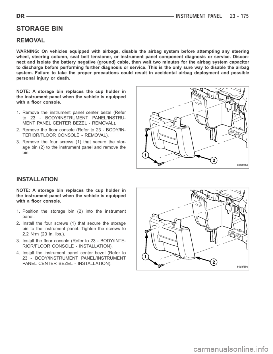
STORAGE BIN
REMOVAL
WARNING: On vehicles equipped with airbags, disable the airbag system before attempting any steering
wheel, steering column, seat belt tensioner, or instrument panel component diagnosis or service. Discon-
nect and isolate the battery negative (ground) cable, then wait two minutes for the airbag system capacitor
to discharge before performing further diagnosis or service. This is the only sure way to disable the airbag
system. Failure to take the proper precautions could result in accidentalairbag deployment and possible
personal injury or death.
NOTE: A storage bin replaces the cup holder in
the instrument panel when the vehicle is equipped
with a floor console.
1. Remove the instrument panel center bezel (Refer
to 23 - BODY/INSTRUMENT PANEL/INSTRU-
MENT PANEL CENTER BEZEL - REMOVAL).
2. Removethefloorconsole(Referto23-BODY/IN-
TERIOR/FLOOR CONSOLE - REMOVAL).
3. Remove the four screws (1) that secure the stor-
age bin (2) to the instrument panel and remove the
bin.
INSTALLATION
NOTE: A storage bin replaces the cup holder in
the instrument panel when the vehicle is equipped
with a floor console.
1. Position the storage bin (2) into the instrument
panel.
2. Install the four screws (1) that secure the storage
bin to the instrument panel. Tighten the screws to
2.2 Nꞏm (20 in. lbs.).
3. Install the floor console (Refer to 23 - BODY/INTE-
RIOR/FLOOR CONSOLE - INSTALLATION).
4. Install the instrument panel center bezel (Refer to
23 - BODY/INSTRUMENT PANEL/INSTRUMENT
PANEL CENTER BEZEL - INSTALLATION).