Page 159 of 5267
5.COMPARE SRI MILEAGE WITH ODOMETER
Compare the SRI Mileage stored with the Instrument Panel Odometer.
Is the mileage within the specified range displayed on the scan tool?
Ye s>>
Te s t C o m p l e t e .
No>>
Update the mileage and retest the SRI Memory.
Perform the POWERTRAIN VERIFICATION TEST. (Refer to 9 - ENGINE - STANDARD PROCEDURE)
Page 161 of 5267
5.COMPARE SRI MILEAGE WITH ODOMETER
Compare the SRI Mileage stored with the Instrument Panel Odometer.
Is the mileage within the specified range displayed on the scan tool?
Ye s>>
Te s t C o m p l e t e .
No>>
Update the mileage and retest the SRI Memory.
Perform the POWERTRAIN VERIFICATION TEST. (Refer to 9 - ENGINE - STANDARD PROCEDURE)
Page 727 of 5267

4.S/C SWITCH (RESUME/ACCEL)
Turn the ignition off.
Disconnect the S/C RESUME/ACCEL Switch harness connector.
NOTE: Check connectors - Clean/repair as necessary.
Ignition on, engine not running.
With the scan tool in Sensors, read the S/C Switch volts in the ECM.
Did the S/C Switch volts go above 4.0 volts?
Ye s>>
Replace the Resume/Accel Switch.
Perform POWERTRAIN VERIFICATION TEST VER - 1 (DIESEL). (Refer to 8 - ELECTRICAL/ELEC-
TRONIC CONTROL MODULES/ENGINE CONTROL MODULE - DIAGNOSIS AND TESTING)
No>>
Go To 5
5.CLOCKSPRING SHORTED TO GROUND
Turn the ignition off.
Disconnect the clockspring6-way harness connector (instrument panel
wiring side).
Turn the ignition on.
With the scan tool in Sensors, read the S/C Switch volts in the ECM.
Did the S/C Switch volts change to 5.0 volts?
Ye s>>
Replace the Clockspring.
Perform POWERTRAIN VERIFICATION TEST VER - 1
(DIESEL). (Refer to 8 - ELECTRICAL/ELECTRONIC CON-
TROL MODULES/ENGINE CONTROL MODULE - DIAG-
NOSIS AND TESTING)
No>>
Go To 6
6.S/C SWITCH SIGNAL CIRCUIT SHORTED TO GROUND
Turn the ignition off.
Disconnect the S/C ON/OFF Switch harness connector.
Disconnect the ECM harness connectors.
NOTE: Check connectors - Clean/repair as necessary.
Measure the resistance between the S/C Switch Signal circuit and
ground (B-) at S/C ON/OFF Switch harness connector.
Is the resistance below 5.0 ohms?
Ye s>>
Repair S/C Switch Signal Circuit for a short to ground.
Perform POWERTRAIN VERIFICATION TEST VER - 1
(DIESEL). (Refer to 8 - ELECTRICAL/ELECTRONIC CON-
TROL MODULES/ENGINE CONTROL MODULE - DIAG-
NOSIS AND TESTING)
No>>
Go To 7
Page 1461 of 5267
5.COMPARE SRI MILEAGE WITH ODOMETER
Compare the SRI Mileage stored with the Instrument Panel Odometer.
Is the mileage within the specified range displayed on the scan tool?
Ye s>>
Te s t C o m p l e t e .
No>>
Update the mileage and retest the SRI Memory.
Perform the POWERTRAIN VERIFICATION TEST. (Refer to 9 - ENGINE - STANDARD PROCEDURE)
Page 1593 of 5267

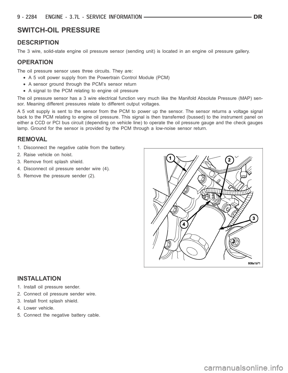
SWITCH-OIL PRESSURE
DESCRIPTION
The 3 wire, solid-state engine oil pressure sensor (sending unit) is located in an engine oil pressure gallery.
OPERATION
The oil pressure sensor uses three circuits. They are:
A 5 volt power supply from the Powertrain Control Module (PCM)
A sensor ground through the PCM’s sensor return
A signal to the PCM relating to engine oil pressure
The oil pressure sensor has a 3 wire electrical function very much like the Manifold Absolute Pressure (MAP) sen-
sor. Meaning different pressures relate to different output voltages.
A 5 volt supply is sent to the sensor from the PCM to power up the sensor. The sensor returns a voltage signal
back to the PCM relating to engine oil pressure. This signal is then transferred (bussed) to the instrument panel on
either a CCD or PCI bus circuit (depending on vehicle line) to operate the oil pressure gauge and the check gauges
lamp. Ground for the sensor is provided by the PCM through a low-noise sensor return.
REMOVAL
1. Disconnect the negative cable from the battery.
2. Raise vehicle on hoist.
3. Remove front splash shield.
4. Disconnect oil pressure sender wire (4).
5. Remove the pressure sender (2).
INSTALLATION
1. Install oil pressure sender.
2. Connect oil pressure sender wire.
3. Install front splash shield.
4. Lower vehicle.
5. Connect the negative battery cable.
Page 1727 of 5267

SWITCH - OIL PRESSURE
DESCRIPTION
DESCRIPTION
The 3 wire, solid-state engine oil pressure sensor (sending unit) is located in an engine oil pressure gallery.
DESCRIPTION
The 3–wire, electrical/mechanical engine oil pressure sensor (sending unit) is located in an engine oil pressure gal-
lery.
OPERATION
OPERATION
The oil pressure sensor uses three circuits. They are:
A 5 volt power supply from the Powertrain Control Module (PCM)
A sensor ground through the PCM’s sensor return
A signal to the PCM relating to engine oil pressure
The oil pressure sensor has a 3 wire electrical function very much like the Manifold Absolute Pressure (MAP) sen-
sor. Meaning different pressures relate to different output voltages.
A 5 volt supply is sent to the sensor from the PCM to power up the sensor. The sensor returns a voltage signal
back to the PCM relating to engine oil pressure. This signal is then transferred (bussed) to the instrument panel on
either a CCD or PCI bus circuit (depending on vehicle line) to operate the oil pressure gauge and the check gauges
lamp. Ground for the sensor is provided by the PCM through a low-noise sensor return.
OPERATION
The oil pressure sensor uses two circuits. They are:
A signal to the PCM relating to engine oil pressure
A sensor ground through the PCM’s sensor return
The oil pressure sensor returns a voltage signal back to the PCM relating toengine oil pressure. This signal is then
transferred (bussed) to the instrument panel on a CCD bus circuit to operate the oil pressure gauge and the check
gauges lamp. Ground for the sensor is provided by the PCM through a low-noise sensor return.
Page 2247 of 5267

SENSOR - FUEL LEVEL SENDING UNIT
DESCRIPTION
The fuel gauge sending unit (fuel level sensor) is attached to the side of the fuel pump module. The sending unit
consists of a float, an arm, and a variable resistor track (card).
OPERATION
The fuel pump module has 4 different circuits (wires). Two of these circuits are used for the fuel gauge sending unit
for fuel gauge operation, and for certain OBD II emission requirements. The other 2 wires are used for electric fuel
pump operation.
For Fuel Gauge Operation:A constant current source is supplied to the resistor track on the fuel gauge sending
unit. This is fed directly from the Powertrain Control Module (PCM).NOTE: For diagnostic purposes, this 12V
power source can only be verified with the circuit opened (fuel pump moduleelectrical connector
unplugged). With the connectors plugged, output voltages will vary from about 0.6 volts at FULL, to about
8.6 volts at EMPTY (about 8.6 volts at EMPTY for Jeep models, and about 7.0 volts at EMPTY for Dodge
Truck models).The resistor track is used to vary the voltage (resistance) depending on fuel tank float level. As fuel
level increases, the float and arm move up, which decreases voltage. As fuel level decreases, the float and arm
move down, which increases voltage. The varied voltage signal is returnedback to the PCM through the sensor
return circuit.
Both of the electrical circuits between the fuel gauge sending unit and thePCM are hard-wired (not multi-plexed).
After the voltage signal is sent from the resistor track, and back to the PCM, the PCM will interpret the resistance
(voltage) data and send a message across the multi-plex bus circuits to theinstrument panel cluster. Here it is
translated into the appropriate fuel gauge level reading. Refer to Instrument Panel for additional information.
For OBD II Emission Monitor Requirements:The PCM will monitor the voltage output sent from the resistor track
on the sending unit to indicate fuel level. The purpose of this feature is toprevent the OBD II system from recording/
setting false misfire and fuel systemmonitor diagnostic trouble codes. The feature is activated if the fuel level in the
tank is less than approximately 15 percent of its rated capacity. If equipped with a Leak Detection Pump (EVAP
system monitor), this feature will also be activated if the fuel level in the tank is more than approximately 85 percent
of its rated capacity.
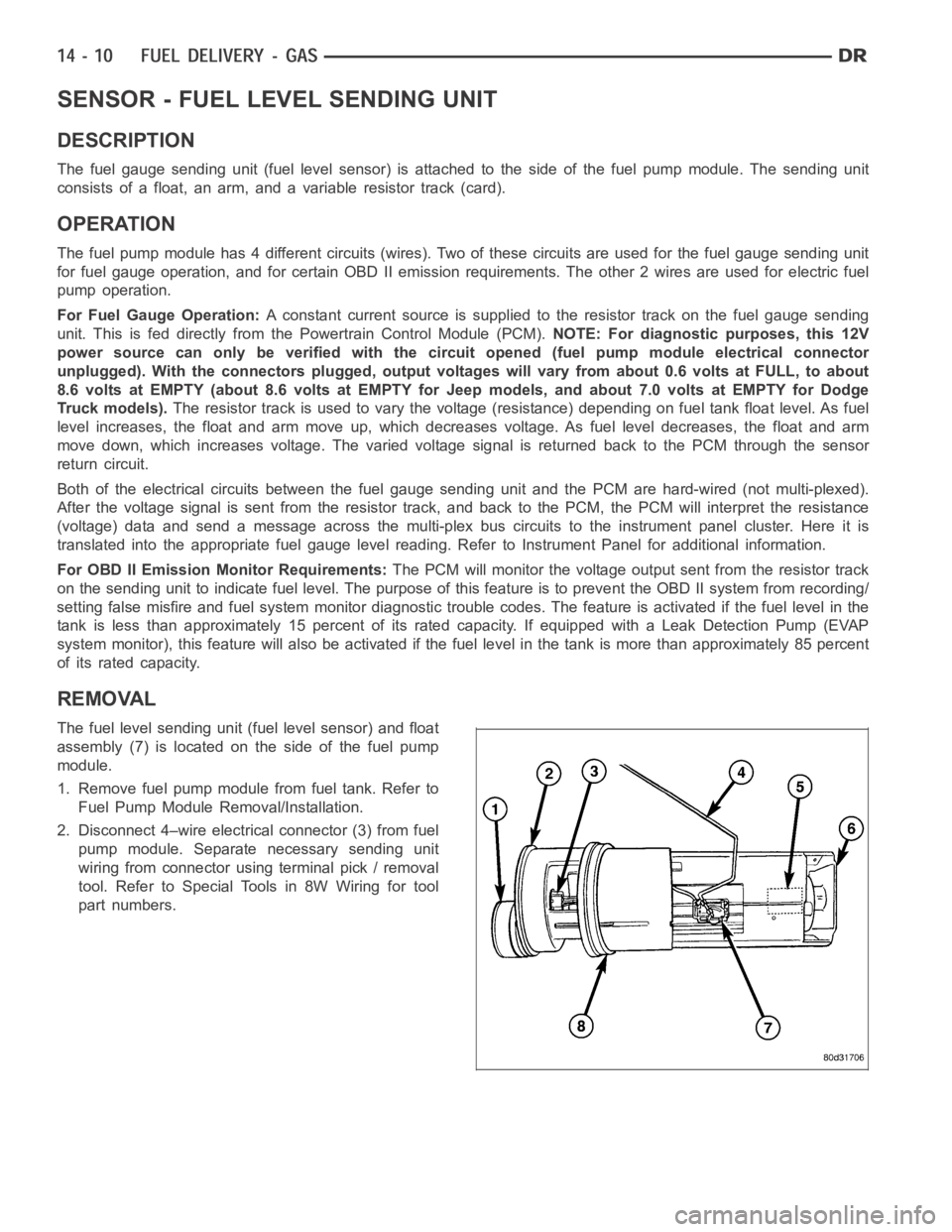
REMOVAL
The fuel level sending unit (fuel level sensor) and float
assembly (7) is located on the side of the fuel pump
module.
1. Remove fuel pump module from fuel tank. Refer to
Fuel Pump Module Removal/Installation.
2. Disconnect 4–wire electrical connector (3) from fuel
pump module. Separate necessary sending unit
wiring from connector using terminal pick / removal
tool. Refer to Special Tools in 8W Wiring for tool
part numbers.
Page 2361 of 5267

SENSOR - FUEL LEVEL SENDING UNIT
DESCRIPTION
The fuel gauge sending unit (fuel level sensor) is attached to the side of the fuel pump module. The sending unit
consists of a float, an arm, and a variable resistor track (card). The fuel transfer (lift) pump is also attached to the
fuel pump module.
OPERATION
For Fuel Gauge Operation:A constant input voltage source of about 12 volts (battery voltage) is supplied to the
resistor track on the fuel gauge sending unit. This is fed directly from theEngine Control Module (ECM).NOTE: For
diagnostic purposes, this 12V power source can only be verified with the circuit opened (fuel tank module
electrical connector unplugged). With the connectors plugged, output voltages will vary from about .6 volts
at FULL, to about 7.0 volts at EMPTY.The resistor track is used to vary the voltage (resistance) depending on fuel
tank float level. As fuel level increases, the float and arm move up, which decreases voltage. As fuel level
decreases, the float and arm move down, which increases voltage. The varied voltage signal is returned back to the
ECM through the sensor return circuit.
Both of the electrical circuits between the fuel gauge sending unit and theECM are hard-wired (not multi-plexed).
After the voltage signal is sent from the resistor track, and back to the ECM, the ECM will interpret the resistance
(voltage) data and send a message across the multi-plex bus circuits to theinstrument panel cluster. Here it is
translated into the appropriate fuel gauge level reading. Refer to Instrument Panel for additional information.
REMOVAL
REMOVAL/INSTALLATION
For diesel removal and installation procedures, refer to the gas section of Fuel System/Fuel Delivery. See Fuel
Level Sending Unit/Sensor Removal/Installation.