2006 DODGE RAM SRT-10 instrument panel
[x] Cancel search: instrument panelPage 2414 of 5267
DESCRIPTION - SRT10
The SRT-10 column has noSTARTposition on the key cylinder. The push starter button switch is mounted on the
Instrument panel center stack. All SRT-10 columns are Tilt columns, Standard cab trucks come with manual trans-
missions, Quad cab trucks come equipped with automatic transmissions.
DIAGNOSIS AND TESTING
STEERING COLUMN
If the vehicle is involved in a front end collision/the air bag has deployedthe column must be inspected. This
inspection will determine if the Column has collapsed. Inspect the columnmounting capsules visually and manually
push and pull them to check for separation or fractures. If capsules are fractured or have moved the column MUST
be replaced.
REMOVAL
WARNING: Before servicing the steering column the airbag system must be disarmed. Refer to electrical
restraint system for service procedures. Failure to do so may result in accidental deployment of the airbag
and possible personal injury.
CAUTION: All fasteners must be torqued to specification to ensure proper operation of the steering column.
1. Position the front wheelsstraight ahead.
2. Disconnect the negative (ground) cable from the battery.
3. Remove the airbag, (Refer to 8 - ELECTRICAL/RE-
STRAINTS/DRIVER AIRBAG - REMOVAL).
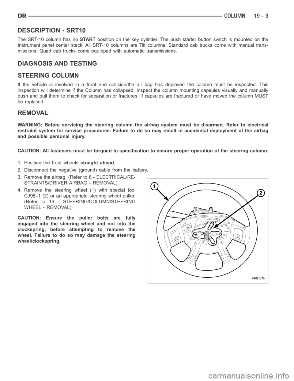
4. Remove the steering wheel (1) with special tool
CJ98–1 (2) or an appropriate steering wheel puller.
(Refer to 19 - STEERING/COLUMN/STEERING
WHEEL - REMOVAL).
CAUTION: Ensure the puller bolts are fully
engaged into the steering wheel and not into the
clockspring, before attempting to remove the
wheel. Failure to do so may damage the steering
wheel/clockspring.
Page 2430 of 5267
TILT LEVER KNOB RELEASE
REMOVAL
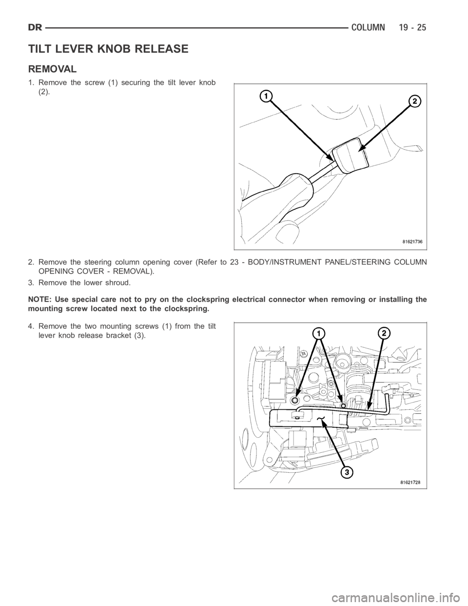
1. Remove the screw (1) securing the tilt lever knob
(2).
2. Remove the steering column opening cover (Refer to 23 - BODY/INSTRUMENTPANEL/STEERING COLUMN
OPENING COVER - REMOVAL).
3. Remove the lower shroud.
NOTE: Use special care not to pry on the clockspring electrical connector whenremovingorinstallingthe
mounting screw located next to the clockspring.
4. Remove the two mounting screws (1) from the tilt
lever knob release bracket (3).
Page 2432 of 5267
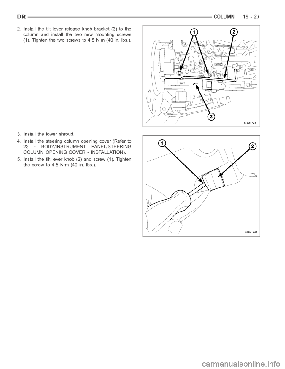
2. Install the tilt lever release knob bracket (3) to the
column and install the two new mounting screws
(1). Tighten the two screws to 4.5 Nꞏm (40 in. lbs.).
3. Install the lower shroud.
4. Install the steering column opening cover (Refer to
23 - BODY/INSTRUMENT PANEL/STEERING
COLUMN OPENING COVER - INSTALLATION).
5. Install the tilt lever knob (2) and screw (1). Tighten
thescrewto4.5Nꞏm(40in.lbs.).
Page 3968 of 5267
SENSOR-TRANSMISSION TEMPERATURE
DESCRIPTION
Transmission fluid temperature readings are supplied
to the transmission control module by the thermistor.
The temperature readings are used to control engage-
ment of the fourth gear overdrive clutch, the converter
clutch, and governor pressure. Normal resistance
value for the thermistor at room temperature is
approximately 2000 ohms.
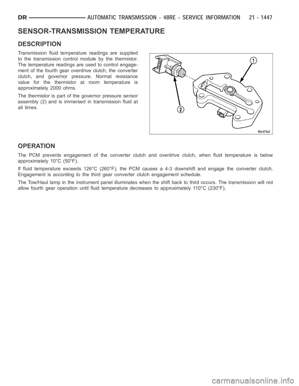
The thermistor is part of the governor pressure sensor
assembly (2) and is immersed in transmission fluid at
all times.
OPERATION
The PCM prevents engagement of the converter clutch and overdrive clutch,when fluid temperature is below
approximately 10°C (50°F).
If fluid temperature exceeds 126°C (260°F), the PCM causes a 4-3 downshiftand engage the converter clutch.
Engagement is according to the third gear converter clutch engagement schedule.
The Tow/Haul lamp in the instrument panel illuminates when the shift back to third occurs. The transmission will not
allow fourth gear operation until fluid temperature decreases to approximately 110°C (230°F).
Page 4216 of 5267
SWITCH-SELECTOR
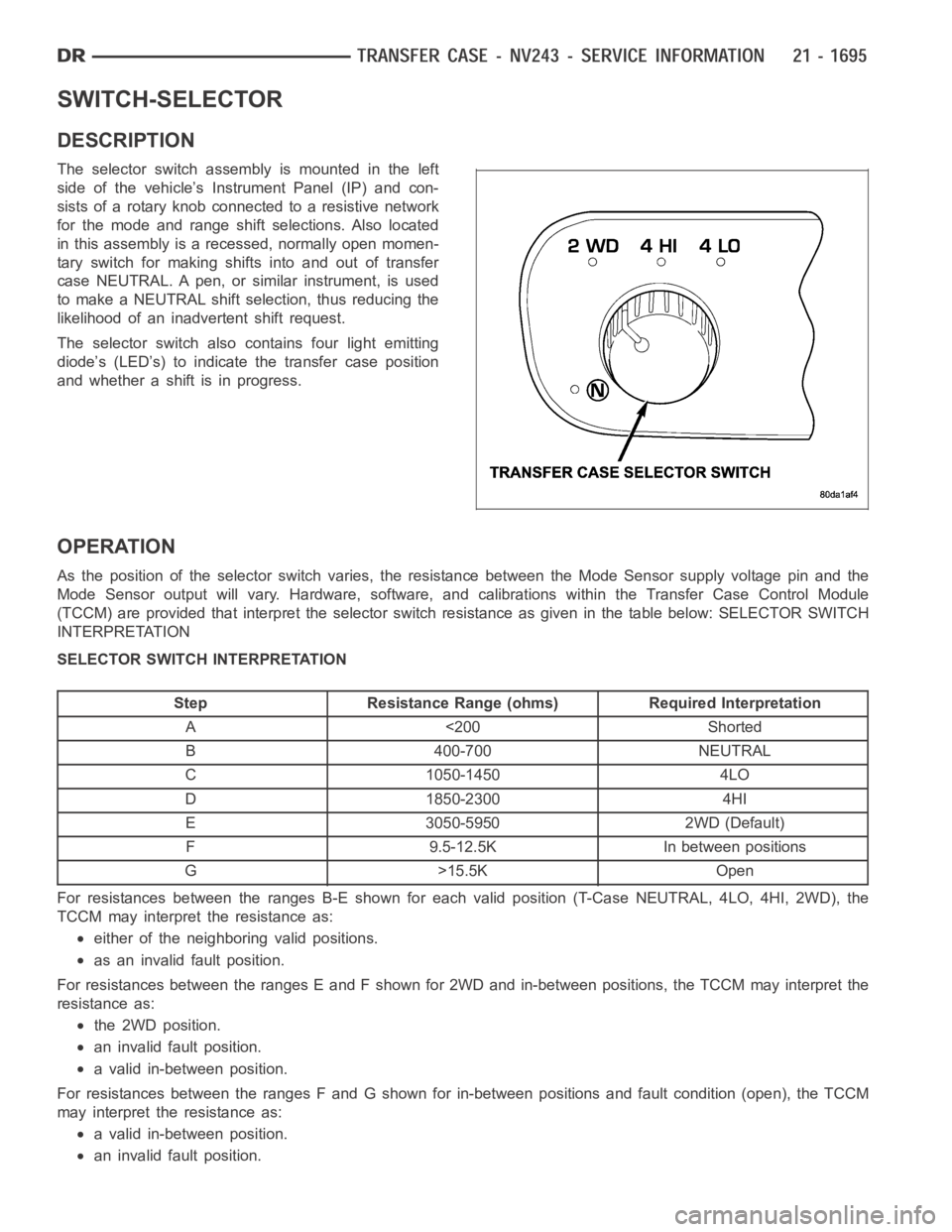
DESCRIPTION
The selector switch assembly is mounted in the left
side of the vehicle’s Instrument Panel (IP) and con-
sists of a rotary knob connected to a resistive network
for the mode and range shift selections. Also located
in this assembly is a recessed, normally open momen-
tary switch for making shifts into and out of transfer
case NEUTRAL. A pen, or similar instrument, is used
to make a NEUTRAL shift selection, thus reducing the
likelihood of an inadvertent shift request.
The selector switch also contains four light emitting
diode’s (LED’s) to indicate the transfer case position
and whether a shift is in progress.
OPERATION
As the position of the selector switchvaries, the resistance between the Mode Sensor supply voltage pin and the
Mode Sensor output will vary. Hardware, software, and calibrations within the Transfer Case Control Module
(TCCM) are provided that interpret the selector switch resistance as giveninthetablebelow:SELECTORSWITCH
INTERPRETATION
SELECTOR SWITCH INTERPRETATION
Step Resistance Range (ohms) Required Interpretation
A <200 Shorted
B 400-700 NEUTRAL
C 1050-1450 4LO
D 1850-2300 4HI
E 3050-5950 2WD (Default)
F 9.5-12.5K In between positions
G>15.5KOpen
For resistances between the ranges B-E shown for each valid position (T-Case NEUTRAL, 4LO, 4HI, 2WD), the
TCCM may interpret the resistance as:
either of the neighboring valid positions.
as an invalid fault position.
For resistances between the ranges E and F shown for 2WD and in-between positions, the TCCM may interpret the
resistance as:
the 2WD position.
an invalid fault position.
a valid in-between position.
For resistances between the ranges F and G shown for in-between positions and fault condition (open), the TCCM
may interpret the resistance as:
a valid in-between position.
an invalid fault position.
Page 4260 of 5267
SWITCH-TRANSFER CASE SELECTOR
DESCRIPTION
The selector switch assembly is mounted in the left side of the vehicle’s Instrument Panel (IP) and consists of a
rotary knob connected to a resistive network for the mode and range shift selections. Also located in this assembly
is a recessed, normally open momentary switch for making shifts into and out of transfer case NEUTRAL. A pen, or
similar instrument, is used to make a NEUTRAL shift selection, thus reducing the likelihood of an inadvertent shift
request.
The selector switch also contains light emitting diode’s (LED’s) to indicate the transfer case position and whether a
shift is in progress.
OPERATION
As the position of the selector switchvaries, the resistance between the Mode Sensor supply voltage pin and the
Mode Sensor output will vary. Hardware, software, and calibrations within the Transfer Case Control Module
(TCCM) are provided that interpret the selector switch resistance as giveninthetablebelow:SELECTORSWITCH
INTERPRETATION
SELECTOR SWITCH INTERPRETATION
Step Resistance Range (ohms) Required Interpretation
A <200 Shorted
B 400-700 NEUTRAL
C 1050-1450 4LO
D 1850-2300 4H
E 3050-5950 AWD (Default)
F 9.5-12.5K In between positions
G>15.5KOpen
For resistances between the ranges B-E shown for each valid position (T-Case NEUTRAL, 4LO, 4HI, AWD), the
TCCM may interpret the resistance as:
either of the neighboring valid positions.
as an invalid fault position.
For resistances between the ranges E and F shown for AWD and in-between positions, the TCCM may interpret the
resistance as:
the AWD position.
an invalid fault position.
a valid in-between position.
For resistances between the ranges F and G shown for in-between positions and fault condition (open), the TCCM
may interpret the resistance as:
a valid in-between position.
an invalid fault position.
For resistances between the ranges A and B shown for the fault condition (short) and , T-Case NEUTRAL, the
TCCM may interpret the resistance as:
the T-Case NEUTRAL position.
an invalid fault position.
The LED’s in the selector assembly are illuminated/flashed in the following manner to indicate a particular condition
or state.
A solidly illuminated LED indicates asuccessfully completed shift and the current operating mode of the trans-
fer case. While a shift has been requested but not yet completed, the LED forthe desired transfer case posi-
tion is flashed.
A flashing operating mode LED for the desired gear indicates that a shift tothat position has been requested,
but all of the driver controllable conditions have not been met. This is in an attempt to notify the driver that the
transmission needs to be put into NEUTRAL, the vehicle speed is too great, or some other condition outlined
Page 4310 of 5267
SWITCH-SELECTOR
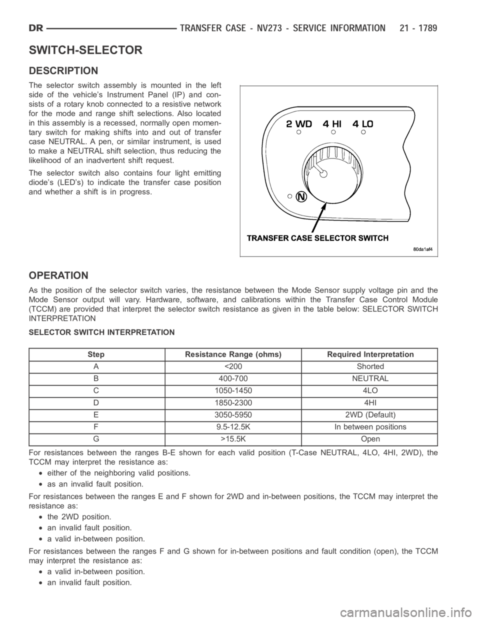
DESCRIPTION
The selector switch assembly is mounted in the left
side of the vehicle’s Instrument Panel (IP) and con-
sists of a rotary knob connected to a resistive network
for the mode and range shift selections. Also located
in this assembly is a recessed, normally open momen-
tary switch for making shifts into and out of transfer
case NEUTRAL. A pen, or similar instrument, is used
to make a NEUTRAL shift selection, thus reducing the
likelihood of an inadvertent shift request.
The selector switch also contains four light emitting
diode’s (LED’s) to indicate the transfer case position
and whether a shift is in progress.
OPERATION
As the position of the selector switchvaries, the resistance between the Mode Sensor supply voltage pin and the
Mode Sensor output will vary. Hardware, software, and calibrations within the Transfer Case Control Module
(TCCM) are provided that interpret the selector switch resistance as giveninthetablebelow:SELECTORSWITCH
INTERPRETATION
SELECTOR SWITCH INTERPRETATION
Step Resistance Range (ohms) Required Interpretation
A <200 Shorted
B 400-700 NEUTRAL
C 1050-1450 4LO
D 1850-2300 4HI
E 3050-5950 2WD (Default)
F 9.5-12.5K In between positions
G>15.5KOpen
For resistances between the ranges B-E shown for each valid position (T-Case NEUTRAL, 4LO, 4HI, 2WD), the
TCCM may interpret the resistance as:
either of the neighboring valid positions.
as an invalid fault position.
For resistances between the ranges E and F shown for 2WD and in-between positions, the TCCM may interpret the
resistance as:
the 2WD position.
an invalid fault position.
a valid in-between position.
For resistances between the ranges F and G shown for in-between positions and fault condition (open), the TCCM
may interpret the resistance as:
a valid in-between position.
an invalid fault position.
Page 4312 of 5267
MOTOR-SHIFT
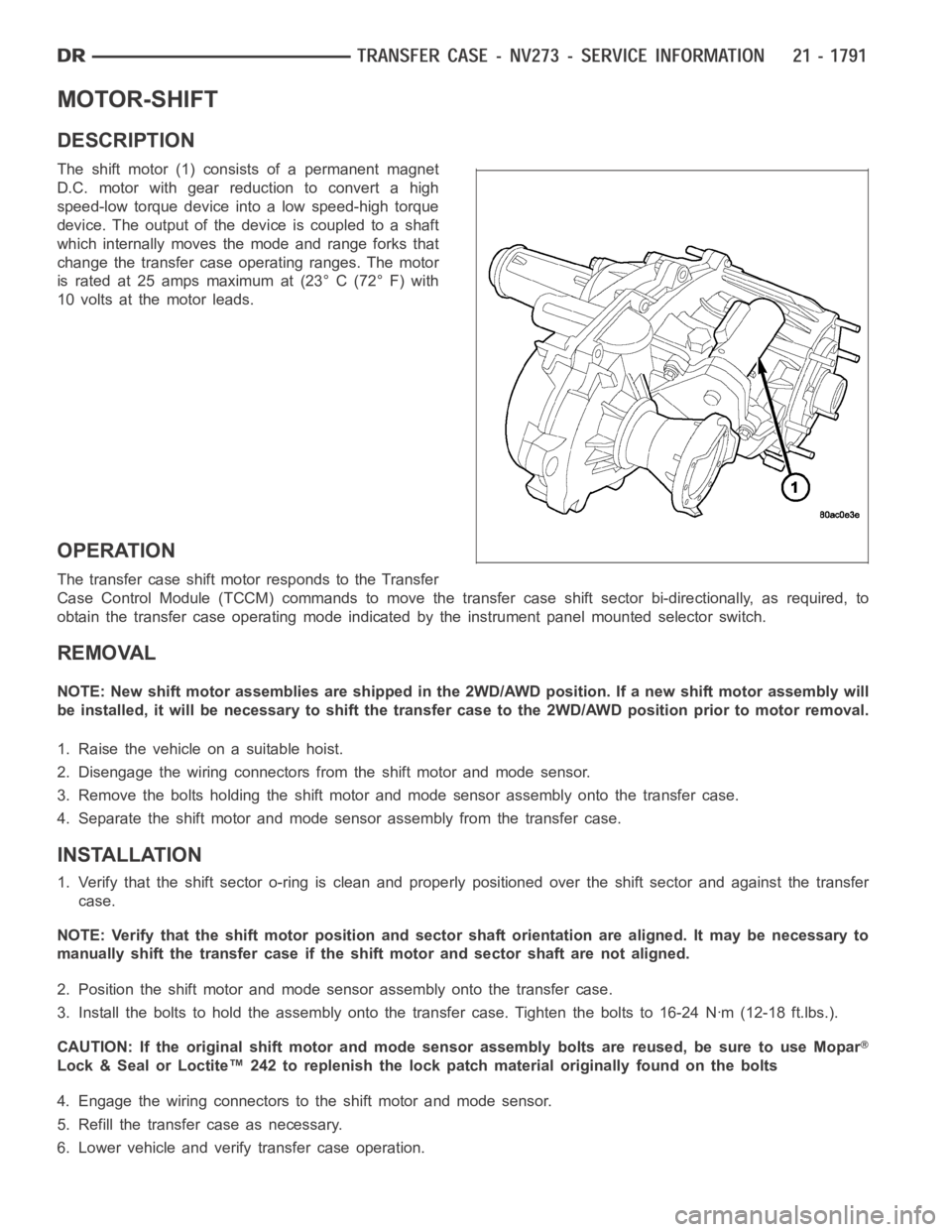
DESCRIPTION
The shift motor (1) consists of a permanent magnet
D.C. motor with gear reduction to convert a high
speed-low torque device into a low speed-high torque
device. The output of the device is coupled to a shaft
which internally moves the mode and range forks that
change the transfer case operating ranges. The motor
is rated at 25 amps maximum at (23° C (72° F) with
10 volts at the motor leads.
OPERATION
The transfer case shift motor responds to the Transfer
Case Control Module (TCCM) commands to move the transfer case shift sectorbi-directionally, as required, to
obtain the transfer case operating mode indicated by the instrument panelmounted selector switch.
REMOVAL
NOTE: New shift motor assemblies are shipped in the 2WD/AWD position. If a new shift motor assembly will
be installed, it will be necessary to shift the transfer case to the 2WD/AWDposition prior to motor removal.
1. Raise the vehicle on a suitable hoist.
2. Disengage the wiring connectors from the shift motor and mode sensor.
3. Remove the bolts holding the shift motor and mode sensor assembly onto the transfer case.
4. Separate the shift motor and mode sensor assembly from the transfer case.
INSTALLATION
1. Verify that the shift sector o-ring is clean and properly positioned over the shift sector and against the transfer
case.
NOTE: Verify that the shift motor position and sector shaft orientation are aligned. It may be necessary to
manually shift the transfer case if the shift motor and sector shaft are notaligned.
2. Position the shift motor and mode sensor assembly onto the transfer case.
3. Install the bolts to hold the assembly onto the transfer case. Tighten the bolts to 16-24 Nꞏm (12-18 ft.lbs.).
CAUTION: If the original shift motor and mode sensor assembly bolts are reused, be sure to use Mopar
Lock & Seal or Loctite™ 242 to replenish the lock patch material originallyfound on the bolts
4. Engage the wiring connectors to the shift motor and mode sensor.
5. Refill the transfer case as necessary.
6. Lower vehicle and verify transfer case operation.