2006 DODGE RAM SRT-10 open gas tank
[x] Cancel search: open gas tankPage 1417 of 5267
3.EVAP PURGE SOLENOID VACUUM LINE
Turn the ignition off.
Inspect the Purge Solenoid Vacuum line that runs from the Evap Purge Solenoid to the throttle body or intake man-
ifold.
Is the vacuum line plugged or kinked?
Ye s>>
Repair or replace the vacuum line from the solenoid to the throttle body / intake manifold.
Perform POWERTRAIN VERIFICATION TEST. (Refer to 9 - ENGINE - STANDARD PROCEDURE)
No>>
Go To 4
NOTE: Reconnect the vacuum line before continuing.
4.CHECKED FOR OTHER BLOCKED HOSES
To continue testing you will need Miller Tool #6872A (Evap System PressurePump) and #8382 (Gas Cap Tester [
]Adapter).
WARNING: The test equipment is designed to be used to pressurize the vehicles Evaporative System only.
Using the equipment in a manner for which it was not designed could be harmful.
WARNING: Keep lit cigarettes, sparks, flames, and other ignition sourcesaway from the test area to prevent
the ignition of explosive gases. Keep the test area well ventilated.
NOTE: The fuel tank should have between 20% and 80% of full to properly test the Evap System.
Attach the power source clip (red) of Miller Tool #6872A to Battery (+) and the ground clip (black) to Battery (-).
Perform the Evaporative System Pressure Pump self test that is specified on the tester cover.
Remove gas cap and install Miller Tool #8382 on the vehicle. Install gas capto Miller Tool #8382. Attach the pres-
sure supply hose from Miller Tool #6872A to the fitting on #8382.
Disconnect the vacuum supply hose at the Leak Detection Pump.
Connect and apply a continuous vacuum supply (i.e. 20”Hg) to the Leak Detection Pump. A vacuum pump such as
an A/C Recovery unit works well.
Ignition on, engine not running.
With the scan tool perform the “Leak Detect Pump Test”. Follow the scan toolinstructions and then press ENTER.
Select#3–HOLDPSI.
On Miller Tool #6872A, set the Pressure/Hold switch to Open and set the Ventswitch to Closed. Turn the pump
timer On and watch the gauge.
When the gauge pressure reaches 14”H2O, turn the Pressure/Hold Valve to Closed.
Turn the pump timer off.
Disconnect the hose at the Evap Canister that goes to the Fuel Tank.
Did the pressure drop when the hose was disconnected?
Ye s>>
Go To 5
No>>
Repair the obstruction in the Evap System between the Evap Canister and thefuel tank.
Perform POWERTRAIN VERIFICATION TEST. (Refer to 9 - ENGINE - STANDARD PROCEDURE)
5.EVAP CANISTER FUNCTION
NOTE: Connect all previously disconnected hoses.
Re-pressurize the Evap System. On Miller Tool #6872A, set the Pressure/Hold switch to Open and set the Vent
switch to Closed.
Turn the pump timer On and watch the gauge.
When the gauge pressure reaches 14” H2O, turn the Pressure/Hold Valve Closed.
Turn the pump timer off.
Page 2242 of 5267

8. Connect other end of jumper wire to positive side of battery.
9. Connect one end of a second jumper wire to remaining injector terminal.
CAUTION: Powering an injector for more than a few seconds will permanentlydamage the injector.
10. Momentarily touch other end of jumper wire to negative terminal of battery for no more than a few seconds.
11. Place a rag or towel below fuel line quick-connect fitting at fuel rail.
12. Disconnect quick-connect fitting at fuel rail. Refer to Quick-Connect Fittings.
13. Return fuel pump relay to PDC.
14. One or more Diagnostic Trouble Codes (DTC’s) may have been stored in PCMmemory due to fuel pump relay
removal. The DRB
scantoolmustbeusedtoeraseaDTC.
STANDARD PROCEDURE - DRAINING FUEL TANK - EXCEPT DIESEL
WARNING: The fuel system may be under constant fuel pressure even with the engine off. This pressure
must be released before servicing fuel tank.
Two different procedures may be used to drain fuel tank: through the fuel fill fitting on tank, or using a diagnostic
scan tool to activate the fuel pump relay. Due to a one-way check valve installed into the fuel fill opening fitting at
the tank, the tank cannot be drained conventionally at the fill cap.
The quickest draining procedure involves removing the rubber fuel fill hose at the fuel tank.
As an alternative procedure, the electric fuel pump may be activated allowingtanktobedrainedatfuelrailcon-
nection. Refer to diagnostic scan tool for fuel pump activation procedures. Before disconnecting fuel line at fuel rail,
release fuel pressure. Refer to the Fuel System Pressure Release Procedure for procedures. Attach end of special
test hose tool number 6631 or 6539 at fuel rail disconnection (tool number 6631isusedon5/16”fuellineswhile
tool number 6539 is used on 3/8” fuel lines). Position opposite end of this hose tool to an approved gasoline drain-
ing station. Activate fuel pump and drain tank until empty.
If electric fuel pump is not operating, fuel must be drained through fuel fill fitting at tank. Refer to following proce-
dures.
1. Release fuel system pressure.
2. Raise vehicle.
3. Thoroughly clean area around fuel fill fitting and rubber fuel fill hoseat tank.
4. If vehicle is equipped with 4 doors and a 6 foot (short) box, remove left-rear tire/wheel.
5. Loosen clamp and disconnect rubber fuel fill hose at tank fitting. Usingan approved gas holding tank, drain fuel
tank through this fitting.
SPECIFICATIONS
FUEL SYSTEM PRESSURE
58 psi +/- 2 psi
TORQUE - EXCEPT DIESEL
DESCRIPTION N-m Ft. Lbs. In. Lbs.
Accelerator Pedal Bracket
Mounting12 - 105
Accelerator Pedal Position
Sensor Bracket-to-Battery
Tray Bolts3-30
Crankshaft Position
Sensor - 3.7L28 21 -
Crankshaft Position
Sensor - 4.7L28 21 -
Page 2258 of 5267
INSTALLATION
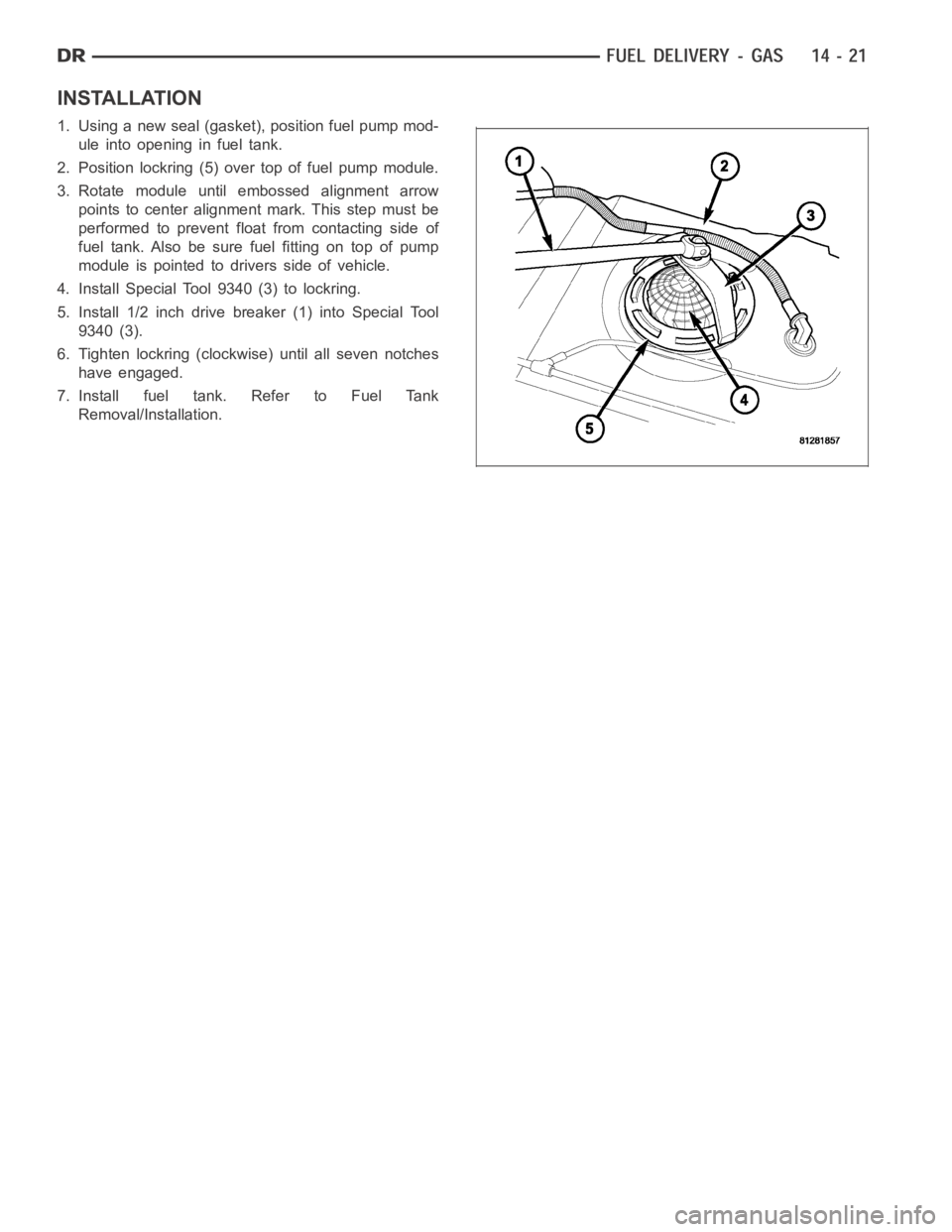
1. Using a new seal (gasket), position fuel pump mod-
uleintoopeninginfueltank.
2. Position lockring (5) over top of fuel pump module.
3. Rotate module until embossed alignment arrow
points to center alignment mark. This step must be
performed to prevent float from contacting side of
fuel tank. Also be sure fuel fitting on top of pump
module is pointed to drivers side of vehicle.
4. Install Special Tool 9340 (3) to lockring.
5. Install 1/2 inch drive breaker (1) into Special Tool
9340 (3).
6. Tighten lockring (clockwise) until all seven notches
have engaged.
7. Install fuel tank. Refer to Fuel Tank
Removal/Installation.
Page 2361 of 5267
SENSOR - FUEL LEVEL SENDING UNIT
DESCRIPTION
The fuel gauge sending unit (fuel level sensor) is attached to the side of the fuel pump module. The sending unit
consists of a float, an arm, and a variable resistor track (card). The fuel transfer (lift) pump is also attached to the
fuel pump module.
OPERATION
For Fuel Gauge Operation:A constant input voltage source of about 12 volts (battery voltage) is supplied to the
resistor track on the fuel gauge sending unit. This is fed directly from theEngine Control Module (ECM).NOTE: For
diagnostic purposes, this 12V power source can only be verified with the circuit opened (fuel tank module
electrical connector unplugged). With the connectors plugged, output voltages will vary from about .6 volts
at FULL, to about 7.0 volts at EMPTY.The resistor track is used to vary the voltage (resistance) depending on fuel
tank float level. As fuel level increases, the float and arm move up, which decreases voltage. As fuel level
decreases, the float and arm move down, which increases voltage. The varied voltage signal is returned back to the
ECM through the sensor return circuit.
Both of the electrical circuits between the fuel gauge sending unit and theECM are hard-wired (not multi-plexed).
After the voltage signal is sent from the resistor track, and back to the ECM, the ECM will interpret the resistance
(voltage) data and send a message across the multi-plex bus circuits to theinstrument panel cluster. Here it is
translated into the appropriate fuel gauge level reading. Refer to Instrument Panel for additional information.
REMOVAL
REMOVAL/INSTALLATION
For diesel removal and installation procedures, refer to the gas section of Fuel System/Fuel Delivery. See Fuel
Level Sending Unit/Sensor Removal/Installation.
Page 2372 of 5267
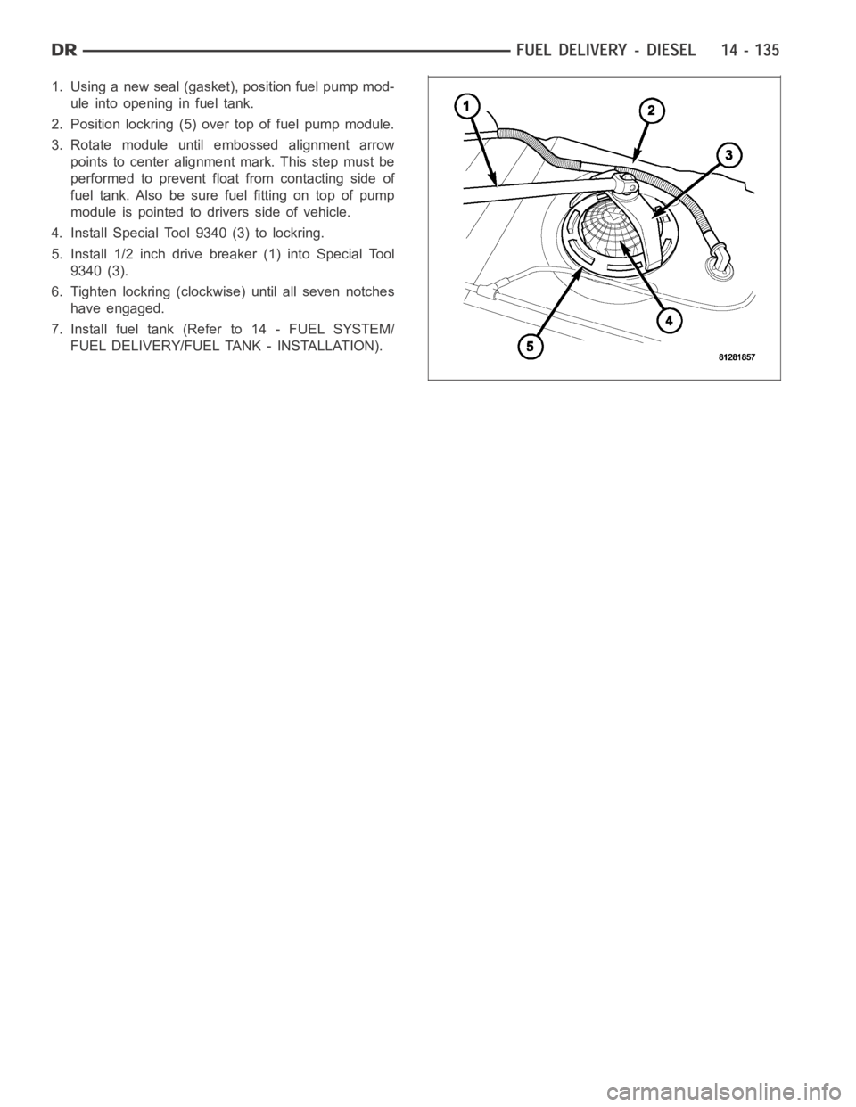
1. Using a new seal (gasket), position fuel pump mod-
uleintoopeninginfueltank.
2. Position lockring (5) over top of fuel pump module.
3. Rotate module until embossed alignment arrow
points to center alignment mark. This step must be
performed to prevent float from contacting side of
fuel tank. Also be sure fuel fitting on top of pump
module is pointed to drivers side of vehicle.
4. Install Special Tool 9340 (3) to lockring.
5. Install 1/2 inch drive breaker (1) into Special Tool
9340 (3).
6. Tighten lockring (clockwise) until all seven notches
have engaged.
7. Install fuel tank (Refer to 14 - FUEL SYSTEM/
FUEL DELIVERY/FUEL TANK - INSTALLATION).
Page 3625 of 5267
TRANSMISSION VERIFICATION TEST VER - 1 (GAS)
1.
1. Inspect the vehicle to ensure that all engine and transmission components are properly installed and connected.
Reassemble and reconnect components as necessary.
2. If any existing diagnostic trouble codes have not been repaired, go to Symptom List and follow path specified.
3. Connect a scan tool to the data link connector.
4. Ensure the fuel tank has at least a quarter tank of fuel. Turn off all accessories.
5. Start and run the engine until the transmission temperature is above 43°C(110°F).
6. Check the transmission fluid level per the Service Information. Adjustif necessary.
7. Road test the vehicle. Make 15 to 20 1-2, 2-3 and 3-4 up shifts. Perform these shifts from a standing start to 72
km/h (45 MPH) with a constant throttle opening of 20-25%.
8. Below 40 km/h (25 MPH), make 5 to 8 wide open throttle kick downs to 1st gear. Allow at least 5 seconds each
in 2nd and 3rd between each kick down.
9. For a specific DTC, drive the vehicle in accordance with the Symptom’s When Monitored and Set Conditions to
verify the repair.
10. If a DTC sets during the road test, return to the Symptom List and follow the path. If no DTC sets, the repair is
complete.
Are there any DTCs or symptoms remaining?
Ye s>>
Repair is not complete, refer to appropriate symptom.
No>>
Repair is complete.
Page 3959 of 5267
VALVE-TORQUE CONVERTER DRAINBACK
DESCRIPTION
GAS ENGINES
The drainback valve is located in the transmission cooler outlet (pressure) line.
DIESEL ENGINE
The converter drainback check valve is located in the in the TOC pressure - supply line, between the engine
mounted TOC and the air to oil TOC.
OPERATION
GAS ENGINES
The valve prevents fluid from draining from the converter into the cooler and lines when the vehicle is shut down for
lengthy periods. Production valves have a hose nipple at one end, while theopposite end is threaded for a flare
fitting. All valves have an arrow (or similar mark) to indicate direction of flow through the valve.
DIESEL ENGINE
The valve prevents fluid from draining from the converter into the cooler and lines when the vehicle is shut down for
lengthy periods. Production valves have pipe thread on one end, while the opposite end is threaded for a flare
fitting, and are threaded into the oil cooler mounted on the side of the engine. All valves have an arrow (or similar
mark) to indicate direction of flow through the valve.
STANDARD PROCEDURE
GAS ENGINES
The converter drainback check valve is located in the cooler outlet (pressure) line near the radiator tank. The valve
prevents fluid drainback when the vehicle is parked for lengthy periods. The valve check ball is spring loaded and
has an opening pressure of approximately 2 psi.
The valve is serviced as an assembly; it is not repairable. Do not clean the valve if restricted, or contaminated by
sludge, or debris. If the valve fails, or if a transmission malfunction occurs that generates significant amounts of
sludge and/or clutch particles and metal shavings, the valve must be replaced.
If the valve is restricted, installed backwards, or in the wrong line, it will cause an transmission overheating condition
and possible transmission failure.
CAUTION: The drainback valve is a one-way flow device. It must be properly orientedintermsofflowdirec-
tion for the cooler to function properly. The valve must be installed in thepressure line. Otherwise flow will
be blocked and would cause an transmission overheating condition and eventual transmission failure.
DIESEL ENGINE
The converter drainback check valve is located in the in the TOC pressure - supply line, between the engine
mounted transmission oil cooler and the air to oil transmission oil cooler. The valve prevents fluid drainback when
the vehicle is parked for lengthy periods. The valve check ball is spring loaded and has an opening pressure of
approximately 2 psi.
The valve is serviced as an assembly; it is not repairable. Do not clean the valve if restricted, or contaminated by
sludge, or debris. If the valve fails, or if a transmission malfunction occurs that generates significant amounts of
sludge and/or clutch particles and metal shavings, the valve must be replaced.
If the valve is restricted, installed backwards, or in the wrong line, it will cause an transmission overheating condition
and possible transmission failure.
Page 5213 of 5267
PUMP-NATURAL VAC LEAK DETECTION
DESCRIPTION
Vehicles equipped with an NGC Powertrain Control Module (PCM) use a Natural Vacuum Leak Detection (NVLD)
pump and system. Vehicles equipped with a JTEC PCM use an LDP (Leak Detection Pump). Refer to Leak Detec-
tion Pump (LDP) for additional information.
The NVLD pump is located in the same area as the leak detection pump. Refer toNVLD Removal / Installation for
additional information.
OPERATION
The Natural Vacuum Leak Detection (NVLD) system is the next generation evaporative leak detection system that
will first be used on vehicles equipped with the Next Generation Controller (NGC). This new system replaces the
leak detection pump as the method of evaporative system leak detection. This is to detect a leak equivalent to a
0.020
(0.5 mm) hole. This system has the capability to detect holes of this size very dependably.
The basic leak detection theory employed with NVLD is the
Gas Law. This is to say that the pressure in a sealed
vessel will change if the temperature of the gas in the vessel changes. The vessel will only see this effect if it is
indeed sealed. Even small leaks will allow the pressure in the vessel to come to equilibrium with the ambient pres-
sure. In addition to the detection of very small leaks, this system has the capability of detecting medium as well as
large evaporative system leaks.
A vent valve seals the canister vent during engine off conditions. If the vapor system has a leak of less than the
failure threshold, the evaporativesystem will be pulled into a vacuum, either due to the cool down from operating
temperature or diurnal ambient temperature cycling. The diurnal effect is considered one of the primary contributors
to the leak determination by this diagnostic. When the vacuum in the systemexceeds about 1
H2O (0.25 KPA), a
vacuum switch closes. The switch closure sends a signal to the NGC. The NGC,via appropriate logic strategies,
utilizes the switch signal, or lack thereof, to make a determination of whether a leak is present.
The NVLD device is designed with a normally open vacuum switch, a normally closed solenoid, and a seal, which
is actuated by both the solenoid and a diaphragm. The NVLD is located on the atmospheric vent side of the can-
ister. The NVLD assembly may be mounted on top of the canister outlet, or in-line between the canister and atmo-
spheric vent filter. The normally open vacuum switch will close with about1
H2O (0.25 KPA) vacuum in the
evaporative system. The diaphragm actuates the switch. This is above the opening point of the fuel inlet check valve
in the fill tube so cap off leaks can be detected. Submerged fill systems must have recirculation lines that do not
have the in-line normally closed check valve that protects the system fromfailednozzleliquidingestion,inorderto
detect cap off conditions.
The normally closed valve in the NVLD is intended to maintain the seal on theevaporative system during the engine
off condition. If vacuum in the evaporative system exceeds 3
to 6H2O (0.75 to 1.5 KPA), the valve will be pulled
off the seat, opening the seal. This will protect the system from excessivevacuum as well as allowing sufficient
purge flow in the event that the solenoid was to become inoperative.
The solenoid actuates the valve to unseal the canister vent while the engine is running. It also will be used to close
the vent during the medium and large leak tests and during the purge flow check. This solenoid requires an initial
1.5 amps of current to pull the valveopen, but after 100 mili-seconds, willbedutycycleddowntoanaverageof
about 150 mA for the remainder of the drive cycle.
Another feature in the device is a diaphragm that will open the seal in the NVLD with pressure in the evaporative
system. The device will
blow offat about 0.5H2O (0.12 KPA) pressure to permit the venting of vapors during
refueling. An added benefit to this is that it will also allow the tank to
breatheduring increasing temperatures, thus
limiting the pressure in the tank to this low level. This is beneficial because the induced vacuum during a subse-
quent declining temperature will achieve the switch closed (pass threshold) sooner than if the tank had to decay
from a built up pressure.
The device itself has 3 wires: Switch sense, solenoid driver and ground. Italso includes a resistor to protect the
switch from a short to battery or a short to ground. The NGC utilizes a high-side driver to energize and duty-cycle
the solenoid.