Page 4475 of 5267

page page
CLUSTER BEZEL
REMOVAL ................................... 139
INSTALLATION .............................. 140
CUP HOLDER
REMOVAL ................................... 141
INSTALLATION .............................. 142
GLOVE BOX
REMOVAL ................................... 144
INSTALLATION .............................. 144
GLOVE BOX LATCH
REMOVAL ................................... 145
INSTALLATION .............................. 146
INSTRUMENT PANEL ASSEMBLY
REMOVAL ................................... 147
INSTALLATION .............................. 155
INSTRUMENT PANEL CENTER BEZEL
REMOVAL ................................... 164
INSTALLATION .............................. 165
INSTRUMENT PANEL DRIVER SIDE BEZEL
REMOVAL ................................... 166INSTALLATION .............................. 166
INSTRUMENT PANEL LOWER SURROUND
REMOVAL ................................... 167
INSTALLATION .............................. 167
INSTRUMENT PANEL TOP COVER
REMOVAL ................................... 169
INSTALLATION .............................. 169
STEERING COLUMN OPENING COVER
REMOVAL ................................... 170
INSTALLATION .............................. 171
STEERING COLUMN OPENING SUPPORT
BRACKET
REMOVAL ................................... 173
INSTALLATION .............................. 174
STORAGE BIN
REMOVAL ................................... 175
INSTALLATION .............................. 175
Page 4481 of 5267
GLOVE BOX
REMOVAL
1. Open the glove box (1).
2. Release the two glove box stops (2) and lower the
glove box downward past the stops.
3. Disengage the glove box hinges from the instru-
ment panel and remove the glove box.
INSTALLATION
1. Engage the hinges of the glove box (1) to the
instrument panel.
2. Press downward on the back edge of the glove box
bin and raise the glove box past the two stops (2).
3. Close the glove box.
Page 4482 of 5267
GLOVE BOX LATCH
REMOVAL
1. Remove the glove box and place it on a workbench
(Refer to 23 - BODY/INSTRUMENT PANEL/
GLOVE BOX - REMOVAL).
2. Remove the 15 screws (1) that secure the glove
box bin (2) and the inner glove box door panel (3)
to the outer glove box door panel (4).
3. Remove the glove box bin and the inner glove box
door panel from the outer glove box door panel.
4. Remove the two screws (1) that secure the glove
box latch (2) to the outer glove box door panel (3)
and remove the latch.
Page 4483 of 5267
INSTALLATION
1. Position the glove box latch (2) into the outer glove
box door panel (3).
2. Install the two screws (1) that secure the glove box
latch to the outer glove box door panel. Tighten the
screws to 2 Nꞏm (17 in. lbs.).
3. Position the inner glove box door panel (3) and the
glove box bin (2) onto the outer glove box door
panel (4).
4. Install the fifteen screws (1) that secure the inner
glove box door panel and the glove box bin to the
outer glove box door panel. Tighten the screws to 2
Nꞏm (17 in. lbs.).
5. Install the glove box (Refer to 23 - BODY/INSTRU-
MENT PANEL/GLOVE BOX - INSTALLATION).
Page 4490 of 5267
19. Disconnect the antenna coaxial cable connector
(1) from the radio coaxial cable connector (2)
located on the right side of the cowl panel.
20. Remove the one bolt (2) that secures the instru-
ment panel (3) to the HVAC housing (1) below the
glove box opening (4).
Page 4493 of 5267
7. Install the three bolts (1) that secure the right side
instrument panel bracket to the cowl panel.
8. Tighten the bolts to 12 Nꞏm (9 ft. lbs.).
9. Install the right a-pillar trim (Refer to 23 - BODY/
INTERIOR/A-PILLAR TRIM - INSTALLATION).
10. Install the right instrument panel side cover.
11. Install the one bolt (2) that secures the instrument
panel (4) to the HVAC housing (1) below the glove
box opening.
Page 4504 of 5267

INSTRUMENT PANEL LOWER SURROUND
REMOVAL
WARNING: On vehicles equipped with airbags, disable the airbag system before attempting any steering
wheel, steering column, seat belt tensioner, or instrument panel component diagnosis or service. Discon-
nect and isolate the battery negative (ground) cable, then wait two minutes for the airbag system capacitor
to discharge before performing further diagnosis or service. This is the only sure way to disable the airbag
system. Failure to take the proper precautions could result in accidentalairbag deployment and possible
personal injury or death.
1. Disconnect and isolate the negative battery cable.
2. Using a trim stick C-4755 or equivalent, from the
notch on the bottom, remove the right instrument
panel side cover.
3. Remove the right side cowl trim panel (Refer to 23
- BODY/INTERIOR/COWL TRIM - REMOVAL).
4. Remove the glove box (Refer to 23 - BODY/IN-
STRUMENT PANEL/GLOVE BOX - REMOVAL).
5. Remove the cup holder or storage bin (depending
on application) (Refer to 23 - BODY/INSTRUMENT
PANEL/CUPHOLDER-REMOVAL)or(Referto23
- BODY/INSTRUMENT PANEL/STORAGE BIN -
REMOVAL).
6. Remove the ash receiver (Refer to 23 - BODY/IN-
STRUMENT PANEL/ASH RECEIVER -
REMOVAL).
7. Remove the steering column opening cover (Refer
to 23 - BODY/INSTRUMENT PANEL/STEERING
COLUMN OPENING COVER - REMOVAL).
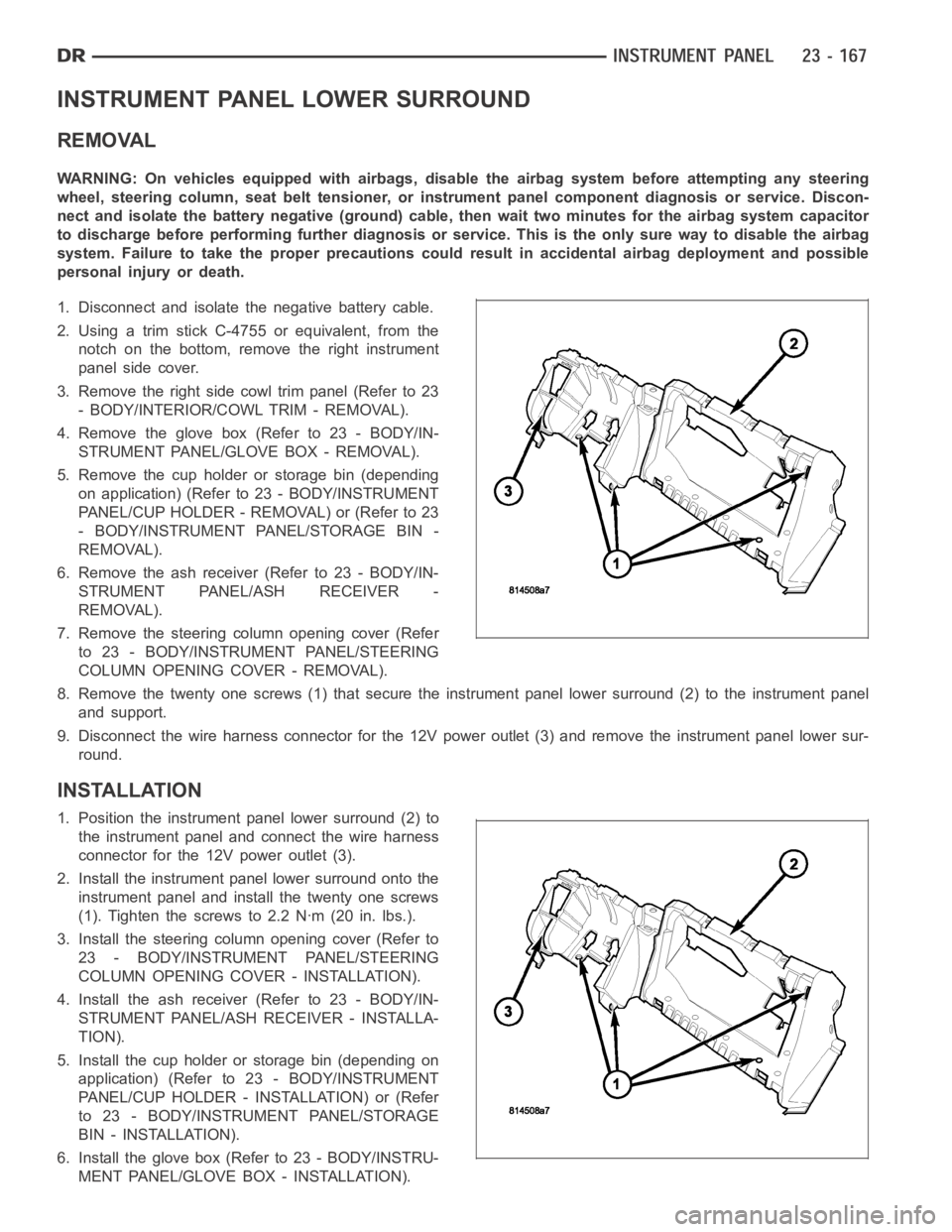
8. Remove the twenty one screws (1) that secure the instrument panel lower surround (2) to the instrument panel
and support.
9. Disconnect the wire harness connector for the 12V power outlet (3) and remove the instrument panel lower sur-
round.
INSTALLATION
1. Position the instrument panel lower surround (2) to
the instrument panel and connect the wire harness
connector for the 12V power outlet (3).
2. Install the instrument panel lower surround onto the
instrument panel and install the twenty one screws
(1). Tighten the screws to 2.2 Nꞏm (20 in. lbs.).
3. Install the steering column opening cover (Refer to
23 - BODY/INSTRUMENT PANEL/STEERING
COLUMN OPENING COVER - INSTALLATION).
4. Install the ash receiver (Refer to 23 - BODY/IN-
STRUMENT PANEL/ASH RECEIVER - INSTALLA-
TION).
5. Install the cup holder or storage bin (depending on
application) (Refer to 23 - BODY/INSTRUMENT
PANEL/CUP HOLDER - INSTALLATION) or (Refer
to 23 - BODY/INSTRUMENT PANEL/STORAGE
BIN - INSTALLATION).
6. Install the glove box (Refer to 23 - BODY/INSTRU-
MENT PANEL/GLOVE BOX - INSTALLATION).
Page 5071 of 5267

REMOVAL
WARNING: On vehicles equipped with airbags, disable the airbag system before attempting any steering
wheel, steering column, or instrument panel component diagnosis or service. Disconnect and isolate the
battery negative (ground) cable, then wait two minutes for the airbag system capacitor to discharge before
performing further diagnosis or service. This is the only sure way to disable the airbag system. Failure to
take the proper precautions could result in accidental airbag deploymentand possible personal injury or
death.
1. Disconnect and isolate the negative battery cable.
2. Remove the glove box from the instrument panel
(Refer to 23 - BODY/INSTRUMENT PANEL/
GLOVE BOX - REMOVAL).
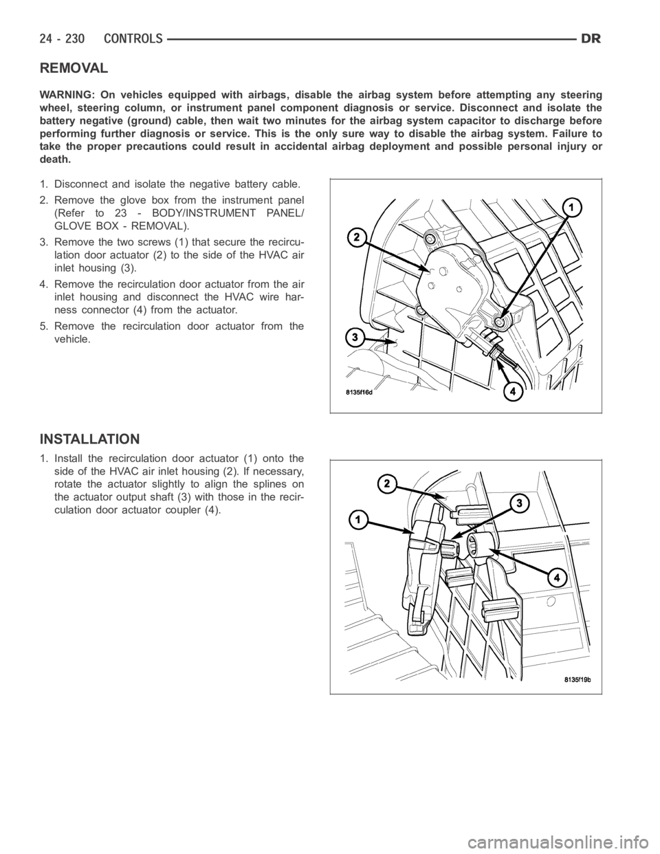
3. Remove the two screws (1) that secure the recircu-
lation door actuator (2) to the side of the HVAC air
inlet housing (3).
4. Remove the recirculation door actuator from the air
inlet housing and disconnect the HVAC wire har-
ness connector (4) from the actuator.
5. Remove the recirculation door actuator from the
vehicle.
INSTALLATION
1. Install the recirculation door actuator (1) onto the
side of the HVAC air inlet housing (2). If necessary,
rotate the actuator slightly to align the splines on
the actuator output shaft (3) with those in the recir-
culation door actuator coupler (4).