2006 DODGE RAM SRT-10 wheel size
[x] Cancel search: wheel sizePage 1698 of 5267
BEARINGS - CRANKSHAFT MAIN
STANDARD PROCEDURE - CRANKSHAFT MAIN BEARING - FITTING
MAIN BEARING JOURNAL DIAMETER (CRANKSHAFT REMOVED)
Crankshaft removed from the cylinder block.
Clean the oil off the main bearing journal.
Determine the maximum diameter of the journal with a micrometer. Measure at two locations 90° apart at each end
of the journal.
The maximum allowable taper is 0.008mm (0.0004 inch.) and maximum out of round is 0.005mm (0.002 inch). Com-
pare the measured diameter with the journal diameter specification (MainBearing Fitting Chart). Select inserts
required to obtain the specified bearing-to-journal clearance.
CRANKSHAFT MAIN BEARING SELECTION
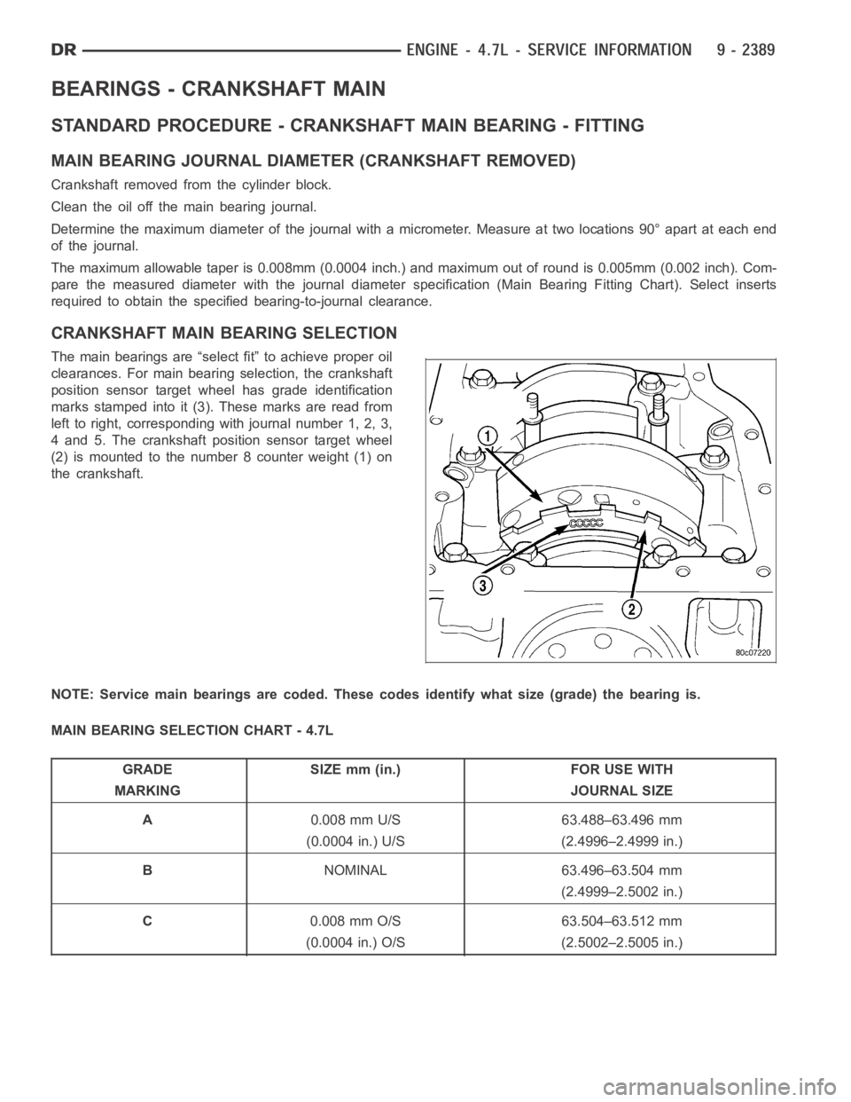
The main bearings are “select fit” to achieve proper oil
clearances. For main bearing selection, the crankshaft
position sensor target wheel has grade identification
marks stamped into it (3). These marks are read from
left to right, corresponding with journal number 1, 2, 3,
4 and 5. The crankshaft position sensor target wheel
(2) is mounted to the number 8 counter weight (1) on
the crankshaft.
NOTE: Service main bearings are coded. These codes identify what size (grade) the bearing is.
MAIN BEARING SELECTION CHART - 4.7L
GRADE SIZE mm (in.) FOR USE WITH
MARKING JOURNAL SIZE
A0.008 mm U/S 63.488–63.496 mm
(0.0004 in.) U/S (2.4996–2.4999 in.)
BNOMINAL 63.496–63.504 mm
(2.4999–2.5002 in.)
C0.008 mm O/S 63.504–63.512 mm
(0.0004 in.) O/S (2.5002–2.5005 in.)
Page 2408 of 5267
CONDITION POSSIBLE CAUSES CORRECTION
RATTLE OR CLUNK 1. Gear mounting bolts loose. 1. Tighten bolts to specification.
2. Loose or damaged suspension
components.2. Inspect and repair suspension.
3. Internal gear noise. 3. Replace steering gear.
4. Pressure hose in contact with other
components.4. Reposition hose.
5. Loose or damaged intermediate shaft or
column.5. Inspect and repair or replace.
CHIRP OR SQUEAL 1. Loose belt. 1. Adjust or replace.
WHINE OR GROWL 1. Low fluid level. 1. Fill to proper level.
2. Pressure hose in contact with other
components.2. Reposition hose.
3. Internal pump noise. 3. Replace pump.
4. Air in fluid 4. Check for leaks, Evacuate air
from P/S system.
SUCKING AIR SOUND 1. Loose return line clamp. 1. Replace clamp.
2. O-ring missing or damaged on hose
fitting.2. Replace o-ring.
3. Low fluid level. 3. Fill to proper level.
4. Air leak between pump and reservoir. 4. Repair as necessary.
5. Reservoir cap not installed correctly. 5. Install reservoir cap correctly.
SCRUBBING OR
KNOCKING1. Wrong tire size. 1. Verify tire size.
BINDING AND STICKING
CONDITION POSSIBLE CAUSE CORRECTION
DIFFICULT TO TURN WHEEL
STICKS OR BINDS1. Low fluid level. 1. Fill to proper level.
2. Tire pressure. 2. Adjust tire pressure.
3. Steering components (ball
joints/tie rod ends).3 Inspect and repair as necessary.
4. Loose belt. 4. Adjust or replace.
5. Low pump pressure. 5. Pressure test and replace if
necessary.
6. Column shaft coupler binding. 6. Replace coupler.
7. Steering gear worn. 7. Replace gear.
8. Pump seized / Stuck valve 8. Replace pump.
Page 4314 of 5267
TIRES/WHEELS
TABLE OF CONTENTS
page page
TIRES/WHEELS
DIAGNOSIS AND TESTING
TIRE AND WHEEL RUNOUT .................. 2
STANDARD PROCEDURE
MATCH MOUNTING .......................... 4
TIRE AND WHEEL BALANCE ................. 5
TIRE ROTATION ............................. 6
SPECIFICATIONS
TORQUE .................................... 7
TIRES
DESCRIPTION
TIRES ....................................... 8
SPARE / TEMPORARY TIRE .................. 8
RADIAL – PLY TIRES ......................... 8
TIRE PRESSURE FOR HIGH SPEEDS......... 9
REPLACEMENT TIRES ....................... 9
TIRE INFLATION PRESSURES ................ 9
DIAGNOSIS AND TESTING
PRESSURE GAUGES ....................... 10
TIRE NOISE OR VIBRATION ................. 10
TREAD WEAR INDICATORS ................. 10
TIRE WEAR PATTERNS ..................... 11
TIRE/VEHICLE LEAD ........................ 12
STANDARD PROCEDURE
TIRE REPAIR AREA ......................... 13
CLEANING
TIRES ..................................... 13SPECIFICATIONS
TIRE REVOLUTIONS PER MILE .............. 13
WHEELS
DESCRIPTION
DESCRIPTION .............................. 15
WHEEL DESIGN ............................ 16
DIAGNOSIS AND TESTING
WHEEL INSPECTION....................... 16
STANDARD PROCEDURE
WHEEL REPLACEMENT ..................... 16
DUAL REAR WHEEL INSTALLATION .......... 18
STUDS
REMOVAL .................................... 20
INSTALLATION ............................... 20
WHEEL COVER
REMOVAL .................................... 22
INSTALLATION
REAR ...................................... 22
FRONT .................................... 22
SPARE TIRE
DESCRIPTION
SPARE / TEMPORARY TIRE ................. 23
FULL SIZE, SPARE WHEEL WITH
MATCHING TIRE............................ 23
Page 4321 of 5267
TIRES
DESCRIPTION
TIRES
Tires are designed and engineered for each specific vehicle. They providethe best overall performance for normal
operation. The ride and handling characteristics match the vehicle’s requirements. With proper care they will give
excellent reliability, traction,skid resistance, and tread life.
Driving habits have more effect on tire life than any other factor. Carefuldrivers will obtain in most cases, much
greater mileage than severe use or careless drivers. A few of the driving habits which will shorten the life of any tire
are:
Rapid acceleration
Severe brake applications
High speed driving
Excessive speeds on turns
Striking curbs and other obstacles
Radial-ply tires are more prone to irregular tread wear. It is important tofollow the tire rotation interval (Refer to 22
- TIRES/WHEELS - STANDARD PROCEDURE). This will help to achieve a greater tread life.
TIRE IDENTIFICATION
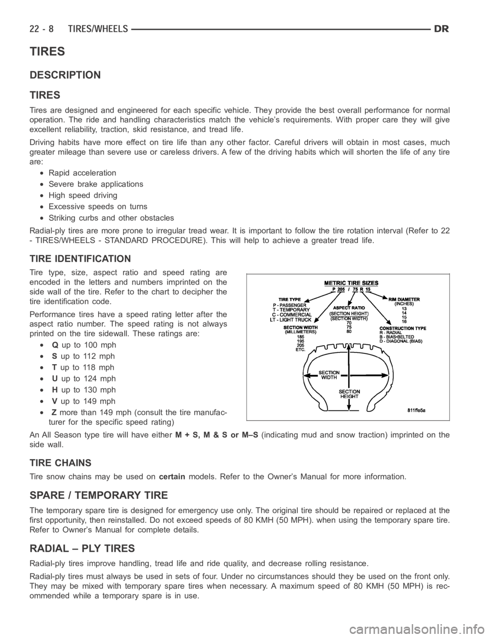
Tire type, size, aspect ratio and speed rating are
encoded in the letters and numbers imprinted on the
side wall of the tire. Refer to the chart to decipher the
tire identification code.
Performance tires have a speed rating letter after the
aspect ratio number. The speed rating is not always
printed on the tire sidewall. These ratings are:
Qup to 100 mph
Sup to 112 mph
Tup to 118 mph
Uup to 124 mph
Hup to 130 mph
Vup to 149 mph
Zmore than 149 mph (consult the tire manufac-
turer for the specific speed rating)
An All Season type tire will have eitherM+S,M&SorM–S(indicating mud and snow traction) imprinted on the
side wall.
TIRE CHAINS
Tire snow chains may be used oncertainmodels. Refer to the Owner’s Manual for more information.
SPARE / TEMPORARY TIRE
The temporary spare tire is designed for emergency use only. The original tire should be repaired or replaced at the
first opportunity, then reinstalled. Do not exceed speeds of 80 KMH (50 MPH). when using the temporary spare tire.
Refer to Owner’s Manual for complete details.
RADIAL – PLY TIRES
Radial-ply tires improve handling, tread life and ride quality, and decrease rolling resistance.
Radial-ply tires must always be used in sets of four. Under no circumstances should they be used on the front only.
They may be mixed with temporary spare tires when necessary. A maximum speedof80KMH(50MPH)isrec-
ommended while a temporary spare is in use.
Page 4322 of 5267
Radial-ply tires have the same load-carrying capacity as other types of tires of the same size. They also use the
same recommended inflation pressures.
The use of oversized tires, either in the front or rear of the vehicle, can cause vehicle drive train failure. This could
also cause inaccurate wheel speed signals when the vehicle is equipped with Anti-Lock Brakes.
The use of tires from different manufactures on the same vehicle is NOT recommended. The proper tire pressure
should be maintained on all four tires.
TIRE PRESSURE FOR HIGH SPEEDS
For proper tire pressure specification refer to the Owners Manual.
REPLACEMENT TIRES
The original equipment tires provide a proper balance of many characteristics such as:
Ride
Noise
Handling
Durability
Tread life
Traction
Rolling resistance
Speed capability
It is recommended that tires equivalent to the original equipment tires beused when replacement is needed.
Failure to use equivalent replacement tires may adversely affect the safety and handling of the vehicle.
The use of oversize tires may cause interference with vehicle components.Under extremes of suspension and
steering travel, interference with vehicle components may cause tire damage.
WARNING: Failure to equip the vehicle with tires having adequate speed capability can result in sudden tire
failure.
TIRE INFLATION PRESSURES
WARNING: Over or under inflated tires can affect
vehicle handling and tread wear. This may cause
the tire to fail suddenly, resulting in loss of vehicle
control.
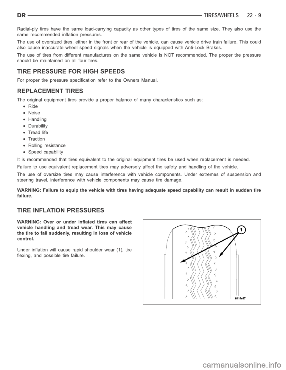
Under inflation will cause rapid shoulder wear (1), tire
flexing, and possible tire failure.
Page 4326 of 5267
STANDARD PROCEDURE
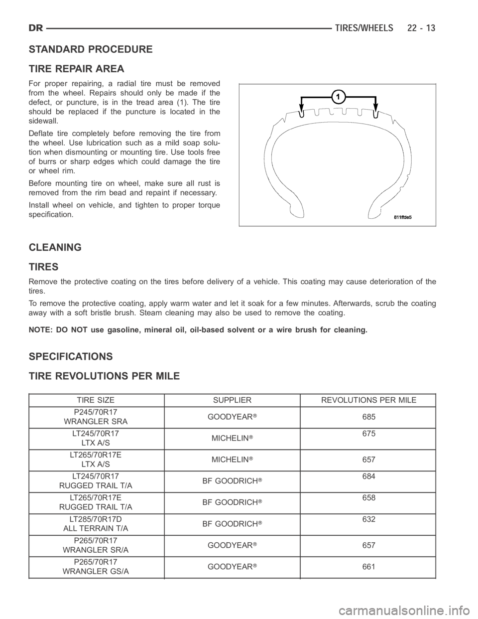
TIRE REPAIR AREA
For proper repairing, a radial tire must be removed
from the wheel. Repairs should only be made if the
defect, or puncture, is in the tread area (1). The tire
should be replaced if the puncture is located in the
sidewall.
Deflate tire completely before removing the tire from
the wheel. Use lubrication such as a mild soap solu-
tion when dismounting or mounting tire. Use tools free
of burrs or sharp edges which could damage the tire
or wheel rim.
Before mounting tire on wheel, make sure all rust is
removed from the rim bead and repaint if necessary.
Install wheel on vehicle, and tighten to proper torque
specification.
CLEANING
TIRES
Remove the protective coating on the tires before delivery of a vehicle. This coating may cause deterioration of the
tires.
To remove the protective coating, apply warm water and let it soak for a few minutes. Afterwards, scrub the coating
away with a soft bristle brush. Steam cleaning may also be used to remove thecoating.
NOTE: DO NOT use gasoline, mineral oil, oil-based solvent or a wire brush for cleaning.
SPECIFICATIONS
TIRE REVOLUTIONS PER MILE
TIRE SIZE SUPPLIER REVOLUTIONS PER MILE
P245/70R17
WRANGLER SRAGOODYEAR
685
LT245/70R17
LT X A / SMICHELIN
675
LT265/70R17E
LT X A / SMICHELIN
657
LT245/70R17
RUGGED TRAIL T/ABF GOODRICH
684
LT265/70R17E
RUGGED TRAIL T/ABF GOODRICH
658
LT285/70R17D
ALL TERRAIN T/ABF GOODRICH
632
P265/70R17
WRANGLER SR/AGOODYEAR
657
P265/70R17
WRANGLER GS/AGOODYEAR
661
Page 4329 of 5267
WHEEL DESIGN
The rim size is on the vehicle safety certification label
located on the drivers door shut face. The size of the
rim is determined by the drivetrain package. Original
equipment wheels/rims are designed for operation up
to the specified maximum vehicle capacity.
All models use stamped steel, cast aluminum or
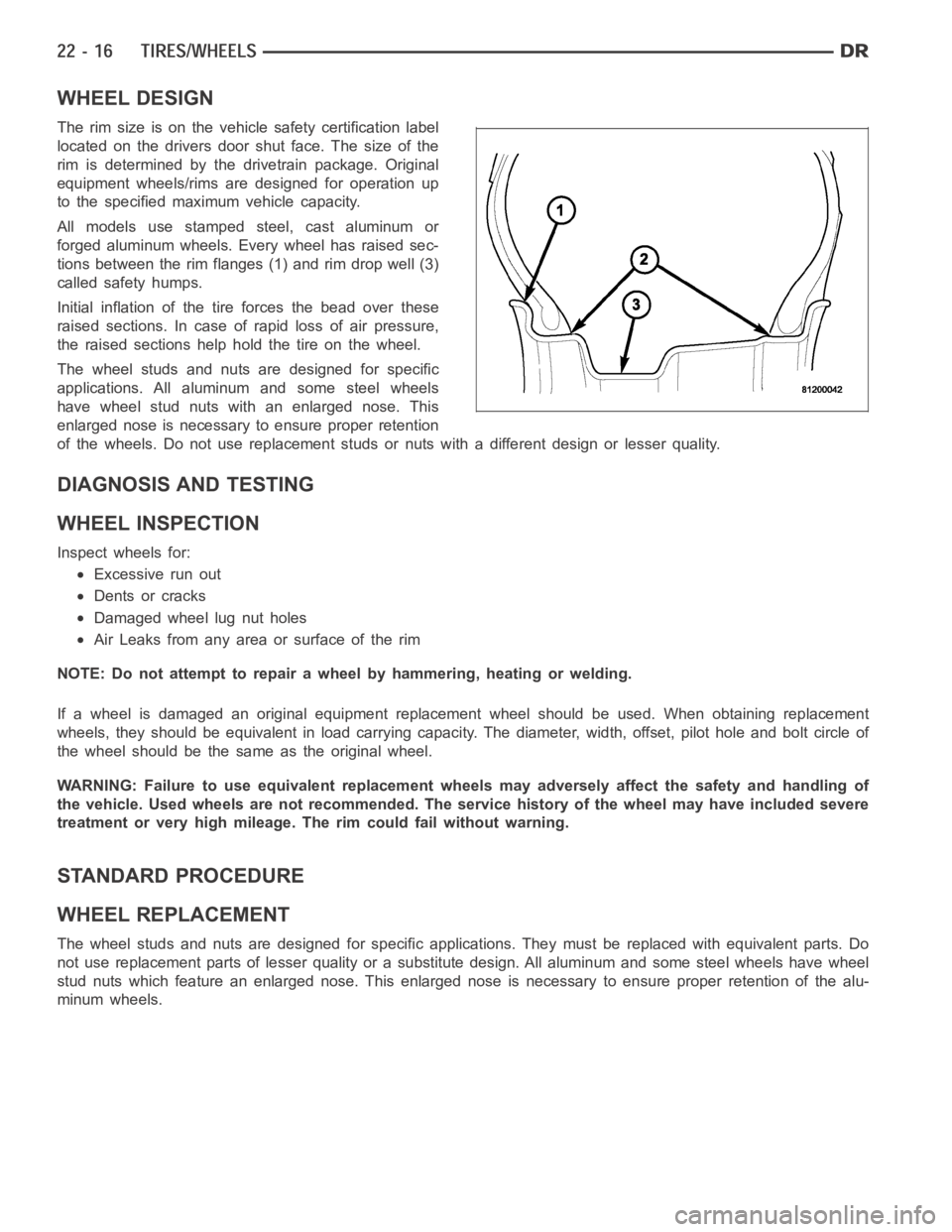
forged aluminum wheels. Every wheel has raised sec-
tions between the rim flanges (1) and rim drop well (3)
called safety humps.
Initial inflation of the tire forces the bead over these
raised sections. In case of rapid loss of air pressure,
the raised sections help hold the tire on the wheel.
The wheel studs and nuts are designed for specific
applications. All aluminum and some steel wheels
have wheel stud nuts with an enlarged nose. This
enlarged nose is necessary to ensure proper retention
of the wheels. Do not use replacement studs or nuts with a different design orlesserquality.
DIAGNOSIS AND TESTING
WHEEL INSPECTION
Inspect wheels for:
Excessive run out
Dents or cracks
Damaged wheel lug nut holes
Air Leaks from any area or surface of the rim
NOTE: Do not attempt to repair a wheel by hammering, heating or welding.
If a wheel is damaged an original equipment replacement wheel should be used. When obtaining replacement
wheels, they should be equivalent in load carrying capacity. The diameter, width, offset, pilot hole and bolt circle of
the wheel should be the same as the original wheel.
WARNING: Failure to use equivalent replacement wheels may adversely affect the safety and handling of
the vehicle. Used wheels are not recommended. The service history of the wheel may have included severe
treatment or very high mileage. The rim could fail without warning.
STANDARD PROCEDURE
WHEEL REPLACEMENT
The wheel studs and nuts are designed for specific applications. They mustbe replaced with equivalent parts. Do
not use replacement parts of lesser quality or a substitute design. All aluminum and some steel wheels have wheel
stud nuts which feature an enlarged nose. This enlarged nose is necessary to ensure proper retention of the alu-
minum wheels.
Page 4333 of 5267

STUDS
REMOVAL
1. Raise and support the vehicle.
2. Remove the wheel and tire assembly.
3. Remove the brake caliper, caliper adapter and
rotor, (Refer to 5 - BRAKES/HYDRAULIC/ME-
CHANICAL/ROTORS - REMOVAL).
4. Remove the wheel speed sensor from the hub.
5. Press the stud from the hub using remover
C-4150A (1).
6. Remove the stud (2) from the hub (1) through the
backing plate access hole (3).
INSTALLATION
1. Install the new stud (2) into the hub flange (1).
2. Install three proper sized washers onto the stud,
then install lug nut with the flat side of the nut
against the washers.
3. Tighten the lug nut until the stud is pulled into the
hub flange. Verify that the stud is properly seated
into the flange.
4. Remove the lug nut and washers.
5. Install the brake rotor, caliper adapter, and caliper,
(Refer to 5 - BRAKES/HYDRAULIC/MECHANICAL/
ROTORS - INSTALLATION).
6. Install the wheel speed sensor.
7. Install the wheel and tire assembly, use new lug nut on the stud or studs that were replaced.