2006 DODGE RAM SRT-10 battery location
[x] Cancel search: battery locationPage 1600 of 5267
MANIFOLD-INTAKE
DESCRIPTION
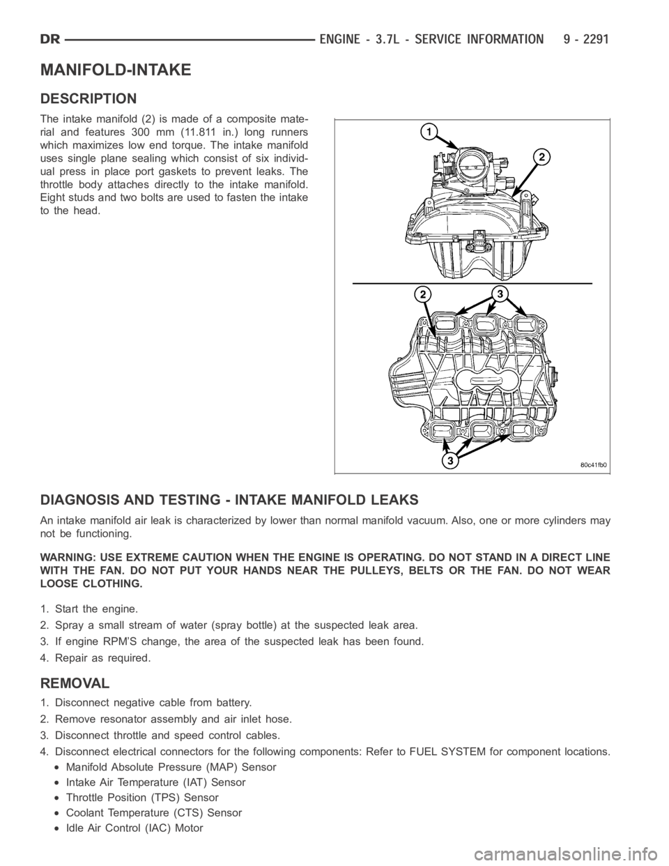
The intake manifold (2) is made of a composite mate-
rial and features 300 mm (11.811 in.) long runners
which maximizes low end torque. The intake manifold
uses single plane sealing which consist of six individ-
ual press in place port gaskets to prevent leaks. The
throttle body attaches directly to the intake manifold.
Eight studs and two bolts are used to fasten the intake
to the head.
DIAGNOSIS AND TESTING -INTAKE MANIFOLD LEAKS
An intake manifold air leak is characterized by lower than normal manifoldvacuum. Also, one or more cylinders may
not be functioning.
WARNING: USE EXTREME CAUTION WHEN THE ENGINE IS OPERATING. DO NOT STAND IN ADIRECT LINE
WITH THE FAN. DO NOT PUT YOUR HANDS NEAR THE PULLEYS, BELTS OR THE FAN. DO NOT WEAR
LOOSE CLOTHING.
1. Start the engine.
2. Spray a small stream of water (spray bottle) at the suspected leak area.
3. If engine RPM’S change, the area of the suspected leak has been found.
4. Repair as required.
REMOVAL
1. Disconnect negative cable from battery.
2. Remove resonator assembly and air inlet hose.
3. Disconnect throttle and speed control cables.
4. Disconnect electrical connectors for the following components: Referto FUEL SYSTEM for component locations.
Manifold Absolute Pressure (MAP) Sensor
Intake Air Temperature (IAT) Sensor
Throttle Position (TPS) Sensor
Coolant Temperature (CTS) Sensor
Idle Air Control (IAC) Motor
Page 1630 of 5267
able in three ounce tubes and has a shelf life of one year. After one year thismaterial will not properly cure. Always
inspect the package for the expiration date before use.
MOPAR
GASKET MAKER
Mopar
Gasket Maker is an anaerobic type gasket material. The material cures in the absence of air when
squeezed between two metallic surfaces. It will not cure if left in the uncovered tube. The anaerobic material is for
use between two machined surfaces. Do not use on flexible metal flanges.
MOPAR
GASKET SEALANT
Mopar
Gasket Sealant is a slow drying, permanently soft sealer. This material isrecommended for sealing
threaded fittings and gaskets against leakage of oil and coolant. Can be used on threaded and machined parts
under all temperatures. This material is used on engines with multi-layersteel (MLS) cylinder head gaskets. This
material also will prevent corrosion. Mopar
Gasket Sealant is available in a 13 oz. aerosol can or 4oz./16 oz. can
w/applicator.
FORM-IN-PLACE GASKET AND SEALER APPLICATION
Assembling parts using a form-in-place gasket requires care but it’s easier than using precut gaskets.
Mopar
Gasket Maker material should be applied sparingly 1 mm (0.040 in.) diameter or less of sealant to one
gasket surface. Be certain the material surrounds each mounting hole. Excess material can easily be wiped off.
Components should be torqued in place within 15 minutes. The use of a locating dowel is recommended during
assembly to prevent smearing material off the location.
Mopar
Engine RTV GEN II or ATF RTV gasket material should be applied in a continuous bead approximately 3
mm (0.120 in.) in diameter. All mounting holes must be circled. For corner sealing, a 3.17 or 6.35 mm (1/8 or 1/4 in.)
drop is placed in the center of the gasket contact area. Uncured sealant maybe removed with a shop towel. Com-
ponents should be torqued in place while the sealant is still wet to the touch (within 10 minutes). The usage of a
locating dowel is recommended during assembly to prevent smearing material off the location.
Mopar
Gasket Sealant in an aerosol can should be applied using a thin, even coat sprayed completely over both
surfaces to be joined, and both sides of a gasket. Then proceed with assembly. Material in a can w/applicator can
be brushed on evenly over the sealing surfaces. Material in an aerosol can shouldbeusedonengineswithmulti-
layer steel gaskets.
REMOVAL
NOTE:Thisprocedureappliestoboththe4X2and4X4vehicles,stepsthatapply to the 4X4 vehicle only,
are identified.
1. Release fuel rail pressure (Refer to 14 - FUEL SYSTEM/FUEL DELIVERY - STANDARD PROCEDURE) then
disconnect the fuel supply quick connect fitting at the fuel rail (Refer to14 - FUEL SYSTEM/FUEL DELIVERY/
QUICK CONNECT FITTING - STANDARD PROCEDURE).
2. Disconnect the battery negative and positive cables.
3. Raise vehicle on hoist.
4. Remove exhaust crossover pipe from exhaust manifolds.
5.4X4 vehiclesDisconnect axle vent tube from left side engine mount.
6. Remove the through bolt retaining nut and bolt from both the left and right side engine mounts.
7.4X4 vehiclesRemove locknut from left and right side engine mount brackets.
8. Disconnect two ground straps from the lower left hand side and one groundstrap from the lower right hand side
of the engine.
Page 1679 of 5267
INSTALLATION
INSTALLATION - RIGHT SIDE
CAUTION: Do not use harsh cleaners to clean the
cylinder head covers. Severe damage to covers
may occur.
1. Clean cylinder head cover and both sealing sur-
faces. Inspect and replace gasket as necessary.
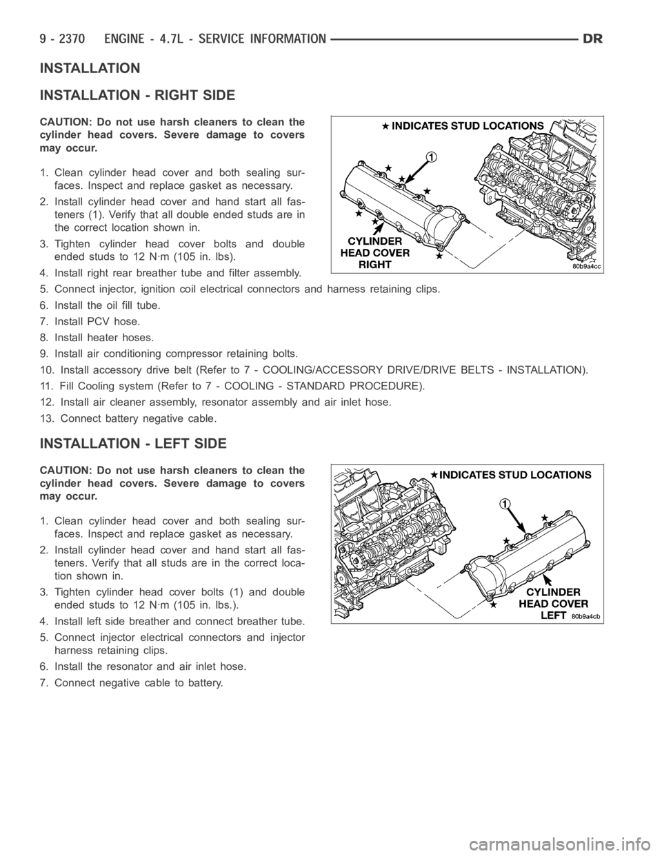
2. Install cylinder head cover and hand start all fas-
teners (1). Verify that all double ended studs are in
the correct location shown in.
3. Tighten cylinder head cover bolts and double
ended studs to 12 Nꞏm (105 in. lbs).
4. Install right rear breather tube and filter assembly.
5. Connect injector, ignition coil electrical connectors and harness retaining clips.
6. Install the oil fill tube.
7. Install PCV hose.
8. Install heater hoses.
9. Install air conditioning compressor retaining bolts.
10. Install accessory drive belt (Refer to 7 - COOLING/ACCESSORY DRIVE/DRIVE BELTS - INSTALLATION).
11. Fill Cooling system (Refer to 7 - COOLING - STANDARD PROCEDURE).
12. Install air cleaner assembly, resonator assembly and air inlet hose.
13. Connect battery negative cable.
INSTALLATION - LEFT SIDE
CAUTION: Do not use harsh cleaners to clean the
cylinder head covers. Severe damage to covers
may occur.
1. Clean cylinder head cover and both sealing sur-
faces. Inspect and replace gasket as necessary.
2. Install cylinder head cover and hand start all fas-
teners. Verify that all studs are in the correct loca-
tion shown in.
3. Tighten cylinder head cover bolts (1) and double
ended studs to 12 Nꞏm (105 in. lbs.).
4. Install left side breather and connect breather tube.
5. Connect injector electrical connectors and injector
harness retaining clips.
6. Install the resonator and air inlet hose.
7. Connect negative cable to battery.
Page 1792 of 5267
1. Perform the Fuel System Pressure Release proce-
dure (Refer to 14 - FUEL SYSTEM/FUEL DELIV-
ERY - STANDARD PROCEDURE). Disconnect the
fuelsupplyline(Referto14-FUELSYSTEM/
FUEL DELIVERY/QUICK CONNECT FITTING -
STANDARD PROCEDURE).
2. Disconnect the battery negative cable.
3. Drain cooling system (Refer to 7 - COOLING -
STANDARD PROCEDURE).
4. Remove the air cleaner resonator and duct work
(Refer to 9 - ENGINE/AIR INTAKE SYSTEM -
REMOVAL).
5. Remove closed crankcase ventilation system.
6. Disconnect the exhaust at the exhaust manifolds.
7. Disconnect the evaporation control system.
8. Disconnect heater hoses.
9. Remove the power steering pump.
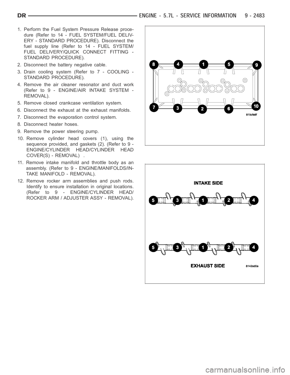
10. Remove cylinder head covers (1), using the
sequence provided, and gaskets (2). (Refer to 9 -
ENGINE/CYLINDER HEAD/CYLINDER HEAD
COVER(S) - REMOVAL) .
11. Remove intake manifold and throttle body as an
assembly. (Refer to 9 - ENGINE/MANIFOLDS/IN-
TAKE MANIFOLD - REMOVAL).
12. Remove rocker arm assemblies and push rods.
Identify to ensure installation in original locations.
(Refer to 9 - ENGINE/CYLINDER HEAD/
ROCKER ARM / ADJUSTER ASSY - REMOVAL).
Page 1852 of 5267
TAPPETS - HYDRAULIC ROLLER
DIAGNOSIS AND TESTING - HYDRAULIC TAPPETS
Before disassembling any part of the engine to correct tappet noise, checkthe oil pressure. If vehicle has no oil
pressure gauge, install a reliable gauge at the pressure sending-unit. The pressure should be between 207-552 kPa
(30-70 psi) at 3,000 RPM.
Check the oil level after the engine reaches normal operating temperature. Allow 5 minutes to stabilize oil level,
check dipstick. The oil level in the pan should never be above the FULL mark or below the ADD OIL mark on
dipstick. Either of these two conditions could be responsible for noisy tappets.
OIL LEVEL
HIGH
If oil level is above the FULL mark, it is possible for the connecting rods todip into the oil. With the engine running,
this condition could create foam in the oil pan. Foam in oil pan would be fed to the hydraulic tappets by the oil pump
causing them to lose length and allow valves to seat noisily.
LOW
Low oil level may allow oil pump to take in air. When air is fed to the tappets,they lose length, which allows valves
to seat noisily. Any leaks on intake side of oil pump through which air can bedrawn will create the same tappet
action. Check the lubrication system from the intake strainer to the pump cover, including the relief valve retainer
cap. When tappet noise is due to aeration, it may be intermittent or constant, and usually more than one tappet will
be noisy. When oil level and leaks have been corrected, operate the engine at fast idle. Run engine for a sufficient
time to allow all of the air inside the tappets to be bled out.
TAPPET NOISE DIAGNOSIS
1. To determine source of tappet noise, crank over engine with cylinder head covers removed.
2. Feel each valve spring or rocker arm to detect noisy tappet. The noisy tappet will cause the affected spring
and/or rocker arm to vibrate or feel rough in operation.
NOTE: Worn valve guides or cocked springs are sometimes mistaken for noisytappets. If such is the case,
noise may be dampened by applying side thrust on the valve spring. If noise is not appreciably reduced, it
can be assumed the noise is in the tappet. Inspect the rocker arm push rod sockets and push rod ends for
wear.
3. Valve tappet noise ranges from light noise to a heavy click. A light noiseis usually caused by excessive leak-
down around the unit plunger, or by the plunger partially sticking in the tappet body cylinder. The tappet should
be replaced. A heavy click is caused by a tappet check valve not seating, or by foreign particles wedged between
the plunger and the tappet body. This will cause the plunger to stick in the down position. This heavy click will be
accompanied by excessive clearance between the valve stem and rocker arm as valve closes. In either case,
tappet assembly should be removed for inspection and cleaning.
4. The valve train generates a noise very much like a light tappet noise during normal operation. Care must be
taken to ensure that tappets are making the noise. If more than one tappet seems to be noisy, it’s probably not
the tappets.
REMOVAL
1. Disconnect the negative cable from the battery.
2. Remove the air cleaner (Refer to 9 - ENGINE/AIR INTAKE SYSTEM - REMOVAL).
3. Remove intake manifold (Refer to 9 - ENGINE/MANIFOLDS/INTAKE MANIFOLD-REMOVAL).
4. Remove cylinder head cover (Refer to 9 - ENGINE/CYLINDER HEAD/CYLINDERHEAD COVER(S) -
REMOVAL).
5. Remove rocker arm assembly and push rods (Refer to 9 - ENGINE/CYLINDER HEAD/ROCKER ARM /
ADJUSTER ASSY - REMOVAL). Identify push rods to ensure installation in original location.
6. Remove the cylinder head (Refer to 9 - ENGINE/CYLINDER HEAD - REMOVAL).
Page 1913 of 5267
MoparEngine RTV GEN II is used to seal components exposed to engine oil. This material is a specially designed
black silicone rubber RTV that retains adhesion and sealing properties when exposed to engine oil. Moisture in the
air causes the material to cure. This material is available in three ounce tubes and has a shelf life of one year. After
one year this material will not properly cure. Always inspect the package for the expiration date before use.
MOPAR
AT F R T V
Mopar
ATF RTV is a specifically designed black silicone rubber RTV that retains adhesion and sealing properties
to seal components exposed to automatic transmission fluid, engine coolants, and moisture. This material is avail-
able in three ounce tubes and has a shelf life of one year. After one year thismaterial will not properly cure. Always
inspect the package for the expiration date before use.
MOPAR
GASKET MAKER
Mopar
Gasket Maker is an anaerobic type gasket material. The material cures in the absence of air when
squeezed between two metallic surfaces. It will not cure if left in the uncovered tube. The anaerobic material is for
use between two machined surfaces. Do not use on flexible metal flanges.
MOPAR
GASKET SEALANT
Mopar
Gasket Sealant is a slow drying, permanently soft sealer. This material isrecommended for sealing
threaded fittings and gaskets against leakage of oil and coolant. Can be used on threaded and machined parts
under all temperatures. This material is used on engines with multi-layersteel (MLS) cylinder head gaskets. This
material also will prevent corrosion. Mopar
Gasket Sealant is available in a 13 oz. aerosol can or 4oz./16 oz. can
w/applicator.
FORM-IN-PLACE GASKET AND SEALER APPLICATION
Assembling parts using a form-in-place gasket requires care but it’s easier than using precut gaskets.
Mopar
Gasket Maker material should be applied sparingly 1 mm (0.040 in.) diameter or less of sealant to one
gasket surface. Be certain the material surrounds each mounting hole. Excess material can easily be wiped off.
Components should be torqued in place within 15 minutes. The use of a locating dowel is recommended during
assembly to prevent smearing material off the location.
Mopar
Engine RTV GEN II or ATF RTV gasket material should be applied in a continuous bead approximately 3
mm (0.120 in.) in diameter. All mounting holes must be circled. For corner sealing, a 3.17 or 6.35 mm (1/8 or 1/4 in.)
drop is placed in the center of the gasket contact area. Uncured sealant maybe removed with a shop towel. Com-
ponents should be torqued in place while the sealant is still wet to the touch (within 10 minutes). The usage of a
locating dowel is recommended during assembly to prevent smearing material off the location.
Mopar
Gasket Sealant in an aerosol can should be applied using a thin, even coat sprayed completely over both
surfaces to be joined, and both sides of a gasket. Then proceed with assembly. Material in a can w/applicator can
be brushed on evenly over the sealing surfaces. Material in an aerosol can shouldbeusedonengineswithmulti-
layer steel gaskets.
STANDARD PROCEDURE - REPAIR DAMAGED OR WORN THREADS
CAUTION: Be sure that the tapped holes maintain the original center line.
Damaged or worn threads can be repaired. Essentially, this repair consistsof:
Drilling out worn or damaged threads.
Tapping the hole with a special Heli-Coil Tap, or equivalent.
Installing an insert into the tapped hole to bring the hole back to its original thread size.
STANDARD PROCEDURE—HYDROSTATIC LOCK
CAUTION: DO NOT use the starter motor to rotate the crankshaft. Severe damage could occur.
When an engine is suspected of hydrostatic lock (regardless of what causedthe problem), follow the steps below.
1. Disconnect the negative cable(s) from the battery.
2. Inspect air cleaner, induction system, and intake manifold to ensure system is dry and clear of foreign material.
Page 1955 of 5267
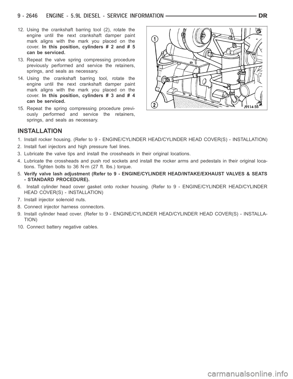
12. Using the crankshaft barring tool (2), rotate the
engine until the next crankshaft damper paint
mark aligns with the mark you placed on the
cover.In this position, cylinders # 2 and # 5
can be serviced.
13. Repeat the valve spring compressing procedure
previously performed and service the retainers,
springs, and seals as necessary.
14. Using the crankshaft barring tool, rotate the
engine until the next crankshaft damper paint
mark aligns with the mark you placed on the
cover.In this position, cylinders # 3 and # 4
can be serviced.
15. Repeat the spring compressing procedure previ-
ously performed and service the retainers,
springs, and seals as necessary.
INSTALLATION
1. Install rocker housing. (Refer to 9 -ENGINE/CYLINDER HEAD/CYLINDER HEAD COVER(S) - INSTALLATION)
2. Install fuel injectors and high pressure fuel lines.
3. Lubricate the valve tips and install the crossheads in their original locations.
4. Lubricate the crossheads and push rod sockets and install the rocker arms and pedestals in their original loca-
tions. Tighten bolts to 36 Nꞏm (27 ft. lbs.) torque.
5.Verify valve lash adjustment (Refer to 9 - ENGINE/CYLINDER HEAD/INTAKE/EXHAUST VALVES & SEATS
- STANDARD PROCEDURE).
6. Install cylinder head cover gasket onto rocker housing. (Refer to 9 - ENGINE/CYLINDER HEAD/CYLINDER
HEAD COVER(S) - INSTALLATION)
7. Install injector solenoid nuts.
8. Connect injector harness connectors.
9. Install cylinder head cover. (Refer to 9 - ENGINE/CYLINDER HEAD/CYLINDER HEAD COVER(S) - INSTALLA-
TION)
10. Connect battery negative cables.
Page 2030 of 5267
3. Using a black light, inspect the entire engine for fluorescent dye, particularly at the suspected area of oil leak. If
the oil leak is found and identified, repair as necessary.
4. If dye is not observed, drive the vehicle at various speeds for approximately 24 km (15 miles), and repeat inspec-
tion.
5.If the oil leak source is not positively identified at this time, proceed with the air leak detection test method
as follows:
1. Disconnect the PCV hoses at the cylinder head covers and plug or cap the outlet on the covers.
2. Attach an air hose with pressure gauge and regulator to the dipstick tube.
CAUTION: Do not subject the engine assembly to more than 20.6 kpa (3 PSI) of test pressure.
3. Gradually apply air pressure from 6.89 kPa (1 psi) to 17.23 kPa (2.5 psi) maximum while applying soapy water
at the suspected source. Adjust the regulator to the suitable test pressure that provides the best bubbles which
will pinpoint the leak source. If the oil leak is detected and identified, repair per service manual procedures.
4. If the leakage occurs at the crankshaft rear oil seal area, refer to the section, Inspection for Rear Seal Area
Leak.
6. If no leaks are detected, turn off the air supply. Remove the air hose, allplugs, and caps. Connect the PCV
hoses. Proceed to next step.
7. Clean the oil off the suspect oil leak area using a suitable solvent. Drive the vehicle at various speeds approx-
imately 24 km (15 miles). Inspect the engine for signs of an oil leak by usinga black light.
NOTE: If oil leakage is observed at the dipstick tube to oil pan location; remove the tube, clean and reseal
using Mopar
Stud & Bearing Mount (press fit tube applications only), and for O-ring style tubes, remove
tube and replace the O-ring seal.
INSPECTION FOR REAR SEAL AREA LEAKS
Since it is sometimes difficult to determine the source of an oil leak in therear seal area of the engine, a more
involved inspection is necessary. The following steps should be followedto help pinpoint the source of the leak.
If the leakage occurs at the crankshaft rear oil seal area:
1. Disconnect the battery.
2. Raise the vehicle.
3. Remove clutch housing inspection cover and inspect rear of block for evidence of oil. Use a black light to check
for the oil leak. If a leak is present in this area, remove transmission for further inspection.
a. Circular spray pattern generally indicates seal leakage or crankshaftdamage.
b. Where leakage tends to run straight down, possible causes are a porous block, oil gallery cup plug or rear
crankshaft seal retainer gasket leak. See proper repair procedures for these items.
4. If no leaks are detected, pressurize the crankcase as previously described.
CAUTION: Do not exceed 20.6 kPa (3 psi).
5. If the leak is not detected, very slowly turn the crankshaft and watch forleakage. If a leak is detected between
the crankshaft and seal while slowly turning the crankshaft, it is possible the crankshaft seal surface is damaged.
The seal area on the crankshaft could have minor nicks or scratches that canbe polished out with emery cloth.
CAUTION: Use extreme caution when crankshaft polishing is necessary to remove minor nicks and
scratches. The crankshaft seal flange is especially machined to complement the function of the rear oil seal.
6. For bubbles that remain steady with shaft rotation, no further inspection can be done until disassembled.
7. After the oil leak root cause and appropriate corrective action have been identified, replace component(s) as
necessary.