2006 DODGE RAM SRT-10 service reset
[x] Cancel search: service resetPage 72 of 5267

4.STARTER
Reconnect the Starter Solenoid harness connector.
Using a 12-volt test light connected ground, probe the (T750) Stater RelayOutput circuit in the Starter Relay har-
ness connector.
Crank the engine.
Does the test light illuminate?
Ye s>>
Replace the Starter in accordance with the Service information
Perform the POWERTRAIN VERIFICATION TEST. (Refer to 9 - ENGINE - STANDARD PROCEDURE)
No>>
Go To 5
5.STARTER RELAY INTERNAL SHORT
Install a substitute relay inplaceoftheStarterRelay.
Reconnect the C9 TIPM harness connector.
Crank the engine.
With a scan tool, read DTCs.
Does the DTC reset?
Ye s>>
Replace the TIPM in accordance with the Service Information.
Perform the POWERTRAIN VERIFICATION TEST. (Refer to 9 - ENGINE - STANDARD PROCEDURE)
No>>
Replace the Starter Relay.
Perform the POWERTRAIN VERIFICATION TEST. (Refer to 9 - ENGINE - STANDARD PROCEDURE)
Page 78 of 5267

4.(T40) STARTER RELAY OUTPUT CIRCUIT SHORTED TO GROUND
Disconnect the C9 TIPM harness connector.
Measure the resistance between ground and the (T40) Starter Relay Output circuit at the C9 TIPM harness con-
nector.
Istheresistancebelow100ohms?
Ye s>>
Repair the short to ground in the (T40) Starter Relay Output circuit.
Perform the POWERTRAIN VERIFICATION TEST. (Refer to 9 - ENGINE - STANDARD PROCEDURE)
No>>
Go To 5
5.(T40) STARTER RELAY OUTPUT CIRCUIT EXCESSIVE RESISTANCE
Measure the resistance of the (T40) Starter Relay Output circuit from the Starter Relay terminal to the C9 TIPM
harness connector.
Is the resistance above 5.0 ohms?
Ye s>>
Repair the excessive resistance in the (T40) Starter Relay Feed circuit.
Perform the POWERTRAIN VERIFICATION TEST. (Refer to 9 - ENGINE - STANDARD PROCEDURE)
No>>
Go To 6
6.STARTER RELAY
Install a known good Relay.
Ignition on, engine not running.
Clear the TIPM DTCs.
Attempt to start the engine.
Does the P127A reset?
Ye s>>
Go To 7
No>>
Replace the Starter Relay.
Perform the POWERTRAIN VERIFICATION TEST. (Refer to 9 - ENGINE - STANDARD PROCEDURE)
7.TOTALLY INTEGRATED POWER MODULE
NOTE: Before continuing, check the TIPM harness connector terminals for corrosion, damage, or terminal
push out. Repair as necessary.
Using the schematics as a guide, inspect the wire harness and connectors.
Pay particular attention to all Power and Ground circuits.
Were any problems found?
Ye s>>
Repair as necessary.
Perform the POWERTRAIN VERIFICATION TEST. (Refer to 9 - ENGINE - STANDARD PROCEDURE)
No>>
Replace the Totally Integrated Power Module per Service Information.
Perform the BODY VERIFICATION TEST – VER 1. (Refer to 8 - ELECTRICAL/ELECTRONIC CON-
TROL MODULES - STANDARD PROCEDURE)
Page 145 of 5267

P1602–PCM NOT PROGRAMMED
For a complete wiring diagramRefer to Section 8W.
When Monitored:
Ignition on and battery voltage greater than 10 volts.
Set Condition:
The PCM has not been programmed.
Possible Causes
PCM
Always perform the Pre-Diagnostic Troubleshooting procedure before proceeding. (Refer to 9 - ENGINE -
DIAGNOSIS AND TESTING).
Diagnostic Test
1.PCM PROGRAMMED
Ignition on, engine not running.
With a scan tool, erase DTCs.
With a scan tool program the PCM.
Start the engine.
Allow the engine to reach normal operating temperature.
With a scan tool, read DTCs.
Does the DTC reset?
Ye s>>
Replace and program the Powertrain Control Module per Service Information.
Perform the POWERTRAIN VERIFICATION TEST. (Refer to 9 - ENGINE - STANDARD PROCEDURE)
No>>
The PCM has been successfully programmed. Test is complete.
Perform the POWERTRAIN VERIFICATION TEST. (Refer to 9 - ENGINE - STANDARD PROCEDURE)
Page 204 of 5267

P2107-ELECTRONIC THROTTLE CONTROL MODULE PROCESSOR
For a complete wiring diagramRefer to Section 8W.
When Monitored:
Ignition on.
Set Condition:
Internal PCM failure. Module will attempt to reset, so you will be able to hear the throttle relearning. If the
condition is continuous, the vehicle may not be driveable. One trip fault.ETC light is flashing.
Possible Causes
POWERTRAIN CONTROL MODULE NEEDS TO BE REPROGRAMMED
Always perform the Pre-Diagnostic Troubleshooting procedure before proceeding. (Refer to 9 - ENGINE -
DIAGNOSIS AND TESTING).
Diagnostic Test
1.REPROGRAM THE POWERTRAIN CONTROL MODULE
Check for any related TSBs.
Verify the PCM is at the latest calibration (flash level).
NOTE: An intermittent loss of power to the PCM without performing an ETC Relearn procedure may cause
this DTC to set.
Flash the Powertrain Control Module per Service Information if any updates are available.
Start the engine.
Allow the engine to reach normal operating temperature.
Operate the accelerator pedal. (do not exceed 3500 rpm)
Test drive the vehicle for 10 miles on a flat road surface.
Does this DTC reset?
Ye s>>
Replace and reprogram the Powertrain Control Module per Service Information.
Perform the POWERTRAIN VERIFICATION TEST. (Refer to 9 - ENGINE - STANDARD PROCEDURE)
No>>
Te s t C o m p l e t e .
Page 205 of 5267

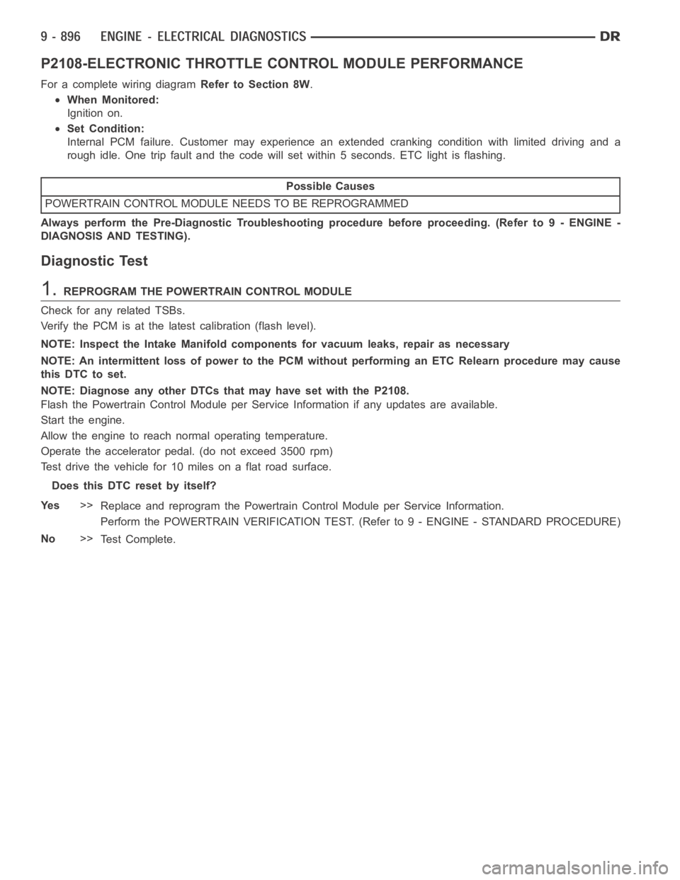
P2108-ELECTRONIC THROTTLE CONTROL MODULE PERFORMANCE
For a complete wiring diagramRefer to Section 8W.
When Monitored:
Ignition on.
Set Condition:
Internal PCM failure. Customer may experience an extended cranking condition with limited driving and a
rough idle. One trip fault and the code will set within 5 seconds. ETC light is flashing.
Possible Causes
POWERTRAIN CONTROL MODULE NEEDS TO BE REPROGRAMMED
Always perform the Pre-Diagnostic Troubleshooting procedure before proceeding. (Refer to 9 - ENGINE -
DIAGNOSIS AND TESTING).
Diagnostic Test
1.REPROGRAM THE POWERTRAIN CONTROL MODULE
Check for any related TSBs.
Verify the PCM is at the latest calibration (flash level).
NOTE: Inspect the Intake Manifold components for vacuum leaks, repair as necessary
NOTE: An intermittent loss of power to the PCM without performing an ETC Relearn procedure may cause
this DTC to set.
NOTE: Diagnose any other DTCs that may have set with the P2108.
Flash the Powertrain Control Module per Service Information if any updates are available.
Start the engine.
Allow the engine to reach normal operating temperature.
Operate the accelerator pedal. (do not exceed 3500 rpm)
Test drive the vehicle for 10 miles on a flat road surface.
Does this DTC reset by itself?
Ye s>>
Replace and reprogram the Powertrain Control Module per Service Information.
Perform the POWERTRAIN VERIFICATION TEST. (Refer to 9 - ENGINE - STANDARD PROCEDURE)
No>>
Te s t C o m p l e t e .
Page 401 of 5267

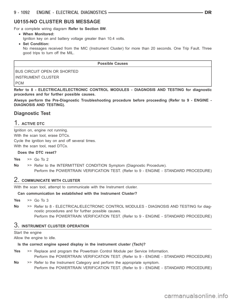
U0155-NO CLUSTER BUS MESSAGE
For a complete wiring diagramRefer to Section 8W.
When Monitored:
Ignition key on and battery voltage greater than 10.4 volts.
Set Condition:
No messages received from the MIC (Instrument Cluster) for more than 20 seconds. One Trip Fault. Three
good trips to turn off the MIL.
Possible Causes
BUS CIRCUIT OPEN OR SHORTED
INSTRUMENT CLUSTER
PCM
Refer to 8 - ELECTRICAL/ELECTRONIC CONTROL MODULES - DIAGNOSIS AND TESTING for diagnostic
procedures and for further possible causes.
Always perform the Pre-Diagnostic Troubleshooting procedure before proceeding (Refer to 9 - ENGINE -
DIAGNOSIS AND TESTING).
Diagnostic Test
1.ACTIVE DTC
Ignition on, engine not running.
With the scan tool, erase DTCs.
Cycle the ignition key on and off several times.
With the scan tool, read DTCs.
Does the DTC reset?
Ye s>>
Go To 2
No>>
Refer to the INTERMITTENT CONDITIONSymptom (Diagnostic Procedure).
Perform the POWERTRAIN VERIFICATION TEST. (Refer to 9 - ENGINE - STANDARD PROCEDURE)
2.COMMUNICATE WITH CLUSTER
With the scan tool, attempt to communicate with the Instrument cluster.
Can communication be established with the Instrument Cluster?
Ye s>>
Go To 3
No>>
Refer to 8 - ELECTRICAL/ELECTRONIC CONTROL MODULES - DIAGNOSIS AND TESTING for diag-
nostic procedures and for further possible causes.
Perform the POWERTRAIN VERIFICATION TEST. (Refer to 9 - ENGINE - STANDARD PROCEDURE)
3.INSTRUMENT CLUSTER OPERATION
Start the engine
Allow the engine to idle.
Is the correct engine speed display in the instrument cluster (Tach)?
Ye s>>
Replace and program the Powertrain Control Module per Service Information.
Perform the POWERTRAIN VERIFICATION TEST. (Refer to 9 - ENGINE - STANDARD PROCEDURE)
No>>
Refer to the Instrument Category and perform the appropriate symptom.
Perform the POWERTRAIN VERIFICATION TEST. (Refer to 9 - ENGINE - STANDARD PROCEDURE)
Page 453 of 5267

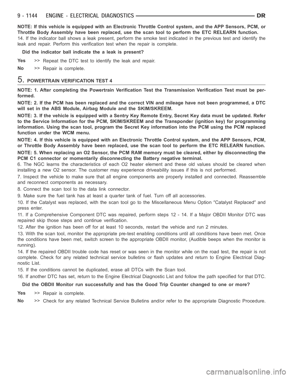
NOTE: If this vehicle is equipped with an Electronic Throttle Control system, and the APP Sensors, PCM, or
Throttle Body Assembly have been replaced, use the scan tool to perform theETC RELEARN function.
14. If the indicator ball shows a leak present, perform the smoke test indicated in the previous test and identify the
leak and repair. Perform this verification test when the repair is complete.
Didtheindicatorballindicatethealeakispresent?
Ye s>>
Repeat the DTC test to identify the leak and repair.
No>>
Repair is complete.
5.POWERTRAIN VERIFICATION TEST 4
NOTE: 1. After completing the Powertrain Verification Test the Transmission Verification Test must be per-
formed.
NOTE: 2. If the PCM has been replaced and the correct VIN and mileage have notbeen programmed, a DTC
will set in the ABS Module, Airbag Module and the SKIM/SKREEM.
NOTE: 3. If the vehicle is equipped with a Sentry Key Remote Entry, Secret Key data must be updated. Refer
to the Service Information for the PCM, SKIM/SKREEM and the Transponder (ignition key) for programming
information. Using the scan tool, program the Secret Key information intothe PCM using the PCM replaced
function under the WCM menu.
NOTE: 4. If this vehicle is equipped with an Electronic Throttle Control system, and the APP Sensors, PCM,
or Throttle Body Assembly have been replaced, use the scan tool to perform the ETC RELEARN function.
NOTE: 5. When replacing an O2 Sensor, the PCM RAM memory must be cleared, either by disconnecting the
PCM C1 connector or momentarily disconnecting the Battery negative terminal.
6. The NGC learns the characteristics of each O2 heater element and these old values should be cleared when
installing a new O2 sensor. The customermay experience driveability issues if this is not performed.
7. Inspect the vehicle to make sure that all engine components are properlyinstalled and connected. Reassemble
and reconnect components as necessary.
8. Connect the scan tool to the data link connector.
9. Make sure the fuel tank has at least a quarter tank of fuel. Turn off all accessories.
10. If the Catalyst was replaced, with the scan tool go to the MiscellaneousMenu Option
Catalyst Replacedand
press enter.
11. If a Comprehensive Component DTC was repaired, perform steps 12 - 14. Ifa Major OBDII Monitor DTC was
repaired skip those steps and continue verification.
12. After the ignition has been off for at least 10 seconds, restart the vehicle and run 2 minutes.
13. With the scan tool, monitor the appropriate pre-test enabling conditions until all conditions have been met. Once
the conditions have been met, switch screen to the appropriate OBDII monitor, (Audible beeps when the monitor is
running).
14. If the repaired OBDII trouble code has reset or was seen in the monitor while on the road test, the repair is not
complete. Check for any related technical service bulletins or flash updates and return to Engine Electrical Diag-
nostic List.
15. If the conditions cannot be duplicated, erase all DTCs with the Scan tool.
16. If another DTC has set, return to the Engine Electrical Diagnostic Listand follow the path specified for that DTC.
Did the OBDII Monitor run successfully and has the Good Trip Counter changed to one or more?
Ye s>>
Repair is complete.
No>>
Check for any related Technical Service Bulletins and/or refer to the appropriate Diagnostic Procedure.
Page 462 of 5267

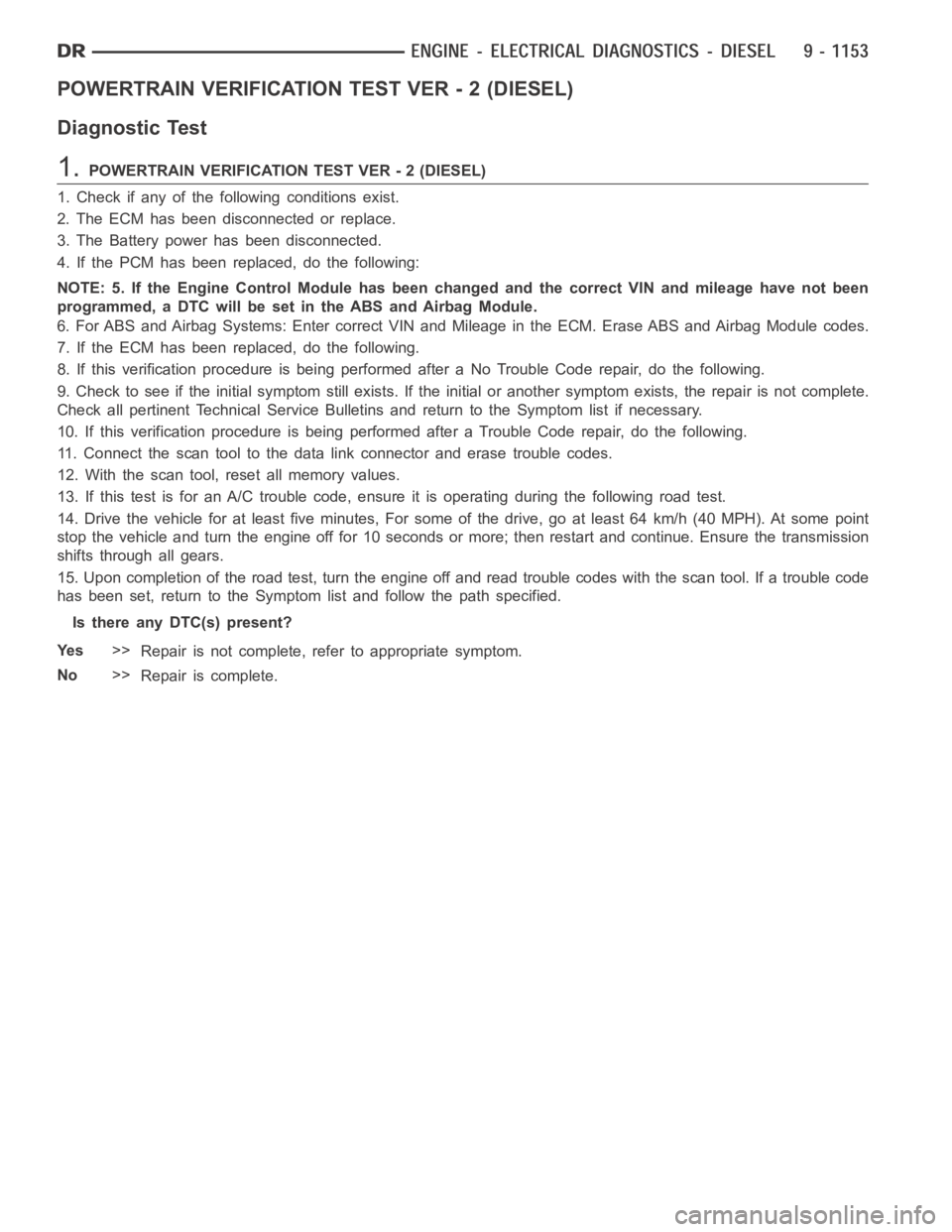
POWERTRAIN VERIFICATION TEST VER - 2 (DIESEL)
Diagnostic Test
1.POWERTRAIN VERIFICATION TEST VER - 2 (DIESEL)
1. Check if any of the following conditions exist.
2. The ECM has been disconnected or replace.
3. The Battery power has been disconnected.
4. If the PCM has been replaced, do the following:
NOTE: 5. If the Engine Control Module has been changed and the correct VIN and mileage have not been
programmed, a DTC will be set in the ABS and Airbag Module.
6. For ABS and Airbag Systems: Enter correct VIN and Mileage in the ECM. Erase ABS and Airbag Module codes.
7. If the ECM has been replaced, do the following.
8. If this verification procedure is being performed after a No Trouble Code repair, do the following.
9. Check to see if the initial symptom still exists. If the initial or another symptom exists, the repair is not complete.
Check all pertinent Technical Service Bulletins and return to the Symptomlist if necessary.
10. If this verification procedure is being performed after a Trouble Coderepair, do the following.
11. Connect the scan tool to the data link connector and erase trouble codes.
12. With the scan tool, reset all memory values.
13. If this test is for an A/C trouble code, ensure it is operating during thefollowing road test.
14. Drive the vehicle for at least five minutes, For some of the drive, go at least 64 km/h (40 MPH). At some point
stop the vehicle and turn the engine off for 10 seconds or more; then restartand continue. Ensure the transmission
shifts through all gears.
15. Upon completion of the road test, turn the engine off and read trouble codeswiththescantool.Ifatroublecode
has been set, return to the Symptom list and follow the path specified.
Is there any DTC(s) present?
Ye s>>
Repair is not complete, refer to appropriate symptom.
No>>
Repair is complete.