Page 4060 of 5267
7.TOTALLY INTEGRATED POWER MODULE (TIPM)
Using the wiring diagram/schematic as a guide, inspect all wiring and connectors that pertain to this circuit.
Were any problems found?
Ye s>>
Repair as necessary.
Perform the TRANSFER CASE VERIFICATION TEST-VER 1. (Refer to 21 - TRANSMISSION/TRANS-
AXLE/TRANSFER CASE - STANDARD PROCEDURE)
No>>
Replace the Totally Integrated Power Module (TIPM) in accordance with theService Information.
Perform the TRANSFER CASE VERIFICATION TEST-VER 1. (Refer to 21 - TRANSMISSION/TRANS-
AXLE/TRANSFER CASE - STANDARD PROCEDURE)
8.INTERMITTENT WIRING AND CONNECTORS
The conditions necessary to set this DTC are not present at this time.
Using the wiring diagram/schematic as a guide, inspect the wiring and connectors.
While monitoring the scan tool data relative to this circuit, wiggle test the wiring and connectors.
Look for the data to change or for the DTC to reset during the wiggle test.
Were any problems found?
Ye s>>
Repair as necessary.
Perform the TRANSFER CASE VERIFICATION TEST-VER 1. (Refer to 21 - TRANSMISSION/TRANS-
AXLE/TRANSFER CASE - STANDARD PROCEDURE)
No>>
Te s t c o m p l e t e .
Page 4073 of 5267
7.FRONT AXLE DISCONNECT (FAD) MODULE
Using the wiring diagram/schematic as a guide, inspect all wiring and connectors that pertain to this circuit.
Were any problems found?
Ye s>>
Repair as necessary.
Perform the TRANSFER CASE VERIFICATION TEST-VER 1. (Refer to 21 - TRANSMISSION/TRANS-
AXLE/TRANSFER CASE - STANDARD PROCEDURE)
No>>
Replace the Front Axle Disconnect (FAD) Module in accordance with the Service Information.
Perform the TRANSFER CASE VERIFICATION TEST-VER 1. (Refer to 21 - TRANSMISSION/TRANS-
AXLE/TRANSFER CASE - STANDARD PROCEDURE)
8.TOTALLY INTEGRATED POWER MODULE (TIPM)
Using the wiring diagram/schematic as a guide, inspect all wiring and connectors that pertain to this circuit.
Were any problems found?
Ye s>>
Repair as necessary.
Perform the TRANSFER CASE VERIFICATION TEST-VER 1. (Refer to 21 - TRANSMISSION/TRANS-
AXLE/TRANSFER CASE - STANDARD PROCEDURE)
No>>
Replace the Totally Integrated Power Module (TIPM) in accordance with theService Information.
Perform the TRANSFER CASE VERIFICATION TEST-VER 1. (Refer to 21 - TRANSMISSION/TRANS-
AXLE/TRANSFER CASE - STANDARD PROCEDURE)
9.INTERMITTENT WIRING AND CONNECTORS
The conditions necessary to set this DTC are not present at this time.
Using the schematics as a guide, inspect the wiring and connectors specifictothiscircuit.
Wiggle test the wiring harness and connectors while checking for shorted and open circuits.
Using the scan tool, monitor the data related to this circuit while performing the wiggle test. Look for the data to
change or for the DTC to reset.
Were there any problems found?
Ye s>>
Repair as necessary.
Perform the TRANSFER CASE VERIFICATION TEST-VER 1. (Refer to 21 - TRANSMISSION/TRANS-
AXLE/TRANSFER CASE - STANDARD PROCEDURE)
No>>
Te s t C o m p l e t e .
Page 4077 of 5267
6.FRONT AXLE DISCONNECT (FAD) MODULE
Using the wiring diagram/schematic as a guide, inspect all wiring and connectors that pertain to this circuit.
Were any problems found?
Ye s>>
Repair as necessary.
Perform the TRANSFER CASE VERIFICATION TEST-VER 1. (Refer to 21 - TRANSMISSION/TRANS-
AXLE/TRANSFER CASE - STANDARD PROCEDURE)
No>>
Replace the Front Axle Disconnect (FAD) Module in accordance with the Service Information.
Perform the TRANSFER CASE VERIFICATION TEST-VER 1. (Refer to 21 - TRANSMISSION/TRANS-
AXLE/TRANSFER CASE - STANDARD PROCEDURE)
7.INTERMITTENT WIRING AND CONNECTORS
The conditions necessary to set this DTC are not present at this time.
Using the schematics as a guide, inspect the wiring and connectors specifictothiscircuit.
Wiggle test the wiring harness and connectors while checking for shorted and open circuits.
Using the scan tool, monitor the data related to this circuit while performing the wiggle test. Look for the data to
change or for the DTC to reset.
Were there any problems found?
Ye s>>
Repair as necessary.
Perform the TRANSFER CASE VERIFICATION TEST-VER 1. (Refer to 21 - TRANSMISSION/TRANS-
AXLE/TRANSFER CASE - STANDARD PROCEDURE)
No>>
Te s t C o m p l e t e .
Page 4082 of 5267
7.FRONT AXLE DISCONNECT (FAD) MODULE
Using the wiring diagram/schematic as a guide, inspect all wiring and connectors that pertain to this circuit.
Were any problems found?
Ye s>>
Repair as necessary.
Perform the TRANSFER CASE VERIFICATION TEST-VER 1. (Refer to 21 - TRANSMISSION/TRANS-
AXLE/TRANSFER CASE - STANDARD PROCEDURE)
No>>
Replace the Front Axle Disconnect (FAD) Module in accordance with the Service Information.
Perform the TRANSFER CASE VERIFICATION TEST-VER 1. (Refer to 21 - TRANSMISSION/TRANS-
AXLE/TRANSFER CASE - STANDARD PROCEDURE)
8.TOTALLY INTEGRATED POWER MODULE (TIPM)
Using the wiring diagram/schematic as a guide, inspect all wiring and connectors that pertain to this circuit.
Were any problems found?
Ye s>>
Repair as necessary.
Perform the TRANSFER CASE VERIFICATION TEST-VER 1. (Refer to 21 - TRANSMISSION/TRANS-
AXLE/TRANSFER CASE - STANDARD PROCEDURE)
No>>
Replace the Totally Integrated Power Module (TIPM) in accordance with theService Information.
Perform the TRANSFER CASE VERIFICATION TEST-VER 1. (Refer to 21 - TRANSMISSION/TRANS-
AXLE/TRANSFER CASE - STANDARD PROCEDURE)
9.INTERMITTENT WIRING AND CONNECTORS
The conditions necessary to set this DTC are not present at this time.
Using the schematics as a guide, inspect the wiring and connectors specifictothiscircuit.
Wiggle test the wiring harness and connectors while checking for shorted and open circuits.
Using the scan tool, monitor the data related to this circuit while performing the wiggle test. Look for the data to
change or for the DTC to reset.
Were there any problems found?
Ye s>>
Repair as necessary.
Perform the TRANSFER CASE VERIFICATION TEST-VER 1. (Refer to 21 - TRANSMISSION/TRANS-
AXLE/TRANSFER CASE - STANDARD PROCEDURE)
No>>
Te s t C o m p l e t e .
STANDARD PROCEDURE
Page 4896 of 5267
When Monitored:
With the ignition on.
Set Condition:
If the Totally Integrated Power Module (TIPM) detects an excessive current draw on the (F942) Fused Ignition
Switch Output (Run-Start) circuit for 20 micro seconds when blower motor operation is requested.
Possible Causes
(F942) FUSED IGNITION SWITCH OUTPUT (RUN-START) CIRCUIT SHORTED TO GROUND
BLOWER MOTOR
TIPM
Diagnostic Test
1.VERIFY DTC IS ACTIVE
Turn the blower control switch to off.
Turn the ignition off, wait 10 seconds, and turn the ignition on.
With the scan tool, erase TIPM DTCs.
Turn the ignition off, wait 10 seconds, and turn the ignition on.
Turn the blower control switch to on.
With the scan tool, read TIPM DTCs.
Does this DTC reset?
Ye s>>
Go To 2
No>>
Check for an intermittent condition by inspecting the related wiring harness for chafed, pierced, pinched,
and partially broken wires. Also, inspect the related connectors for broken, bent, corroded, and contam-
inated terminals.
Perform BODY VERIFICATION TEST – VER 1. (Refer to 8 - ELECTRICAL/ELECTRONIC CONTROL
MODULES - STANDARD PROCEDURE).
2.CHECK FOR ACTIVE DTC B10E9–BLOWER MOTOR CONTROL CIRCUIT LOW WITH BLOWER MOTOR
HARNESS CONNECTOR DISCONNECTED
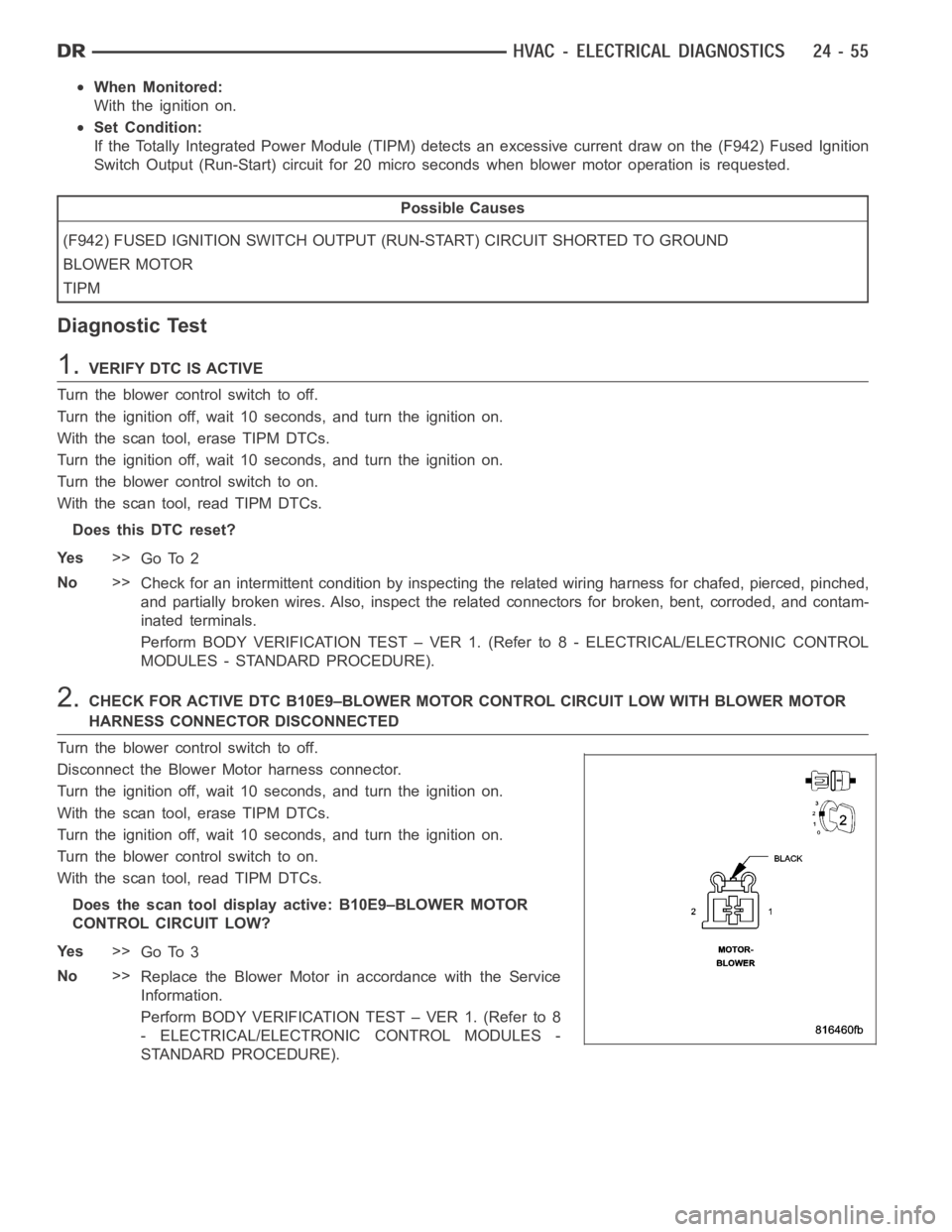
Turn the blower control switch to off.
Disconnect the Blower Motor harness connector.
Turn the ignition off, wait 10 seconds, and turn the ignition on.
With the scan tool, erase TIPM DTCs.
Turn the ignition off, wait 10 seconds, and turn the ignition on.
Turn the blower control switch to on.
With the scan tool, read TIPM DTCs.
Does the scan tool display active: B10E9–BLOWER MOTOR
CONTROL CIRCUIT LOW?
Ye s>>
Go To 3
No>>
Replace the Blower Motor in accordance with the Service
Information.
Perform BODY VERIFICATION TEST – VER 1. (Refer to 8
- ELECTRICAL/ELECTRONIC CONTROL MODULES -
STANDARD PROCEDURE).