2006 DODGE RAM SRT-10 length
[x] Cancel search: lengthPage 451 of 5267
POWERTRAIN VERIFICATION TEST
For a complete wiring diagramRefer to Section 8W.
Diagnostic Test
1.SELECTING THE PROPER VERIFICATION TEST
The following verification test are for different repairs. Select the appropriate Verification test for the
repair that has been completed.
Speed Control repair
Go To 2
Charging System repair
Go To 3
NVLD System repair
Go To 4
All other repairs
Go To 5
2.POWERTRAIN VERIFICATION TEST 1
NOTE: 1. If this vehicle is equipped with an Electronic Throttle Control system, and the APP Sensors, PCM,
or Throttle Body Assembly have been replaced, use the scan tool to perform the ETC RELEARN function.
NOTE: 2. After completing the Powertrain Verification Test the Transmission Verification Test must be per-
formed.
NOTE: 3. If the PCM has been replaced and the correct VIN and mileage have notbeen programmed, a DTC
will set in the ABS Module, Airbag Module and the SKIM/SKREEM.
NOTE: 4. If the vehicle is equipped with a Sentry Key Remote Entry, Secret Key data must be updated. Refer
to the Service Information for the PCM, SKIM/SKREEM and the Transponder (ignition key) for programming
information. Using the scan tool, program the Secret Key information intothe PCM using the PCM replaced
function under the WCM menu.
5. Inspect the vehicle to make sure that all engine components are properlyinstalled and connected.
6. Connect the scan tool to the data link connector and erase all codes.
7. Turn the speed control ON (if equipped, cruise light will be on).
8. Depress and release the SET Switch when the vehicle speed is greater than35 MPH. The speed control should
engage and hold the selected speed.
9. Press and hold the RESUME/ACCEL Switch. The vehicle speed should increase by at least 2 MPH.
10. Press and hold the COAST switch. The vehicle speed should decrease.
11. Using caution, press and release the brake pedal. The speed control should disengage.
12. Bring the vehicle speed back up to 35 MPH.
13. Press the RESUME/ACCEL switch. The speed control should resume the previously set speed.
14. Hold down the SET switch. The vehicle should decelerate.
15. Make sure vehicle speed is greater than 35 mph and release the SET Switch. The vehicle should adjust and set
a new vehicle speed.
16. Press and release the CANCEL switch. The speed control should disengage.
17. Bring the vehicle speed back up above 35 mph and engage speed control.
18. Turn the Speed Control Off. (Cruise light will be off). The speed control should disengage.
NOTE: OVERSHOOT/UNDERSHOOT FOLLOWING SPEED CONTROL SET.
19. If the vehicle operator repeatedly presses and releases the SET buttonwith their foot off of the accelerator
(referred to as
lift foot set), the vehicle may accelerate and exceed the desired set speed by up to 5 mph (8km/h).
20. It may also decelerate to less than the desired set speed, before finally achieving the desired set speed.
21. The Speed Control System has an adaptive strategy that compensates forvehicle-to-vehicle variations in speed
control cable lengths.
22. When the speed control is set with the vehicles operators foot off of theaccelerator pedal, the speed control
thinks there is excessive speed control cable slack and adapts accordingly.
Page 463 of 5267

POWERTRAIN VERIFICATION TEST VER - 4 (DIESEL)
1.POWERTRAIN VERIFICATION TEST VER - 4 (DIESEL)
1. Check if any of the following conditions exist.
2. The ECM has been disconnected or replace.
3. The Battery power has been disconnected.
4. Inspect the vehicle to ensure that all engine components are properly installed and connected. Reassemble and
reconnect components as necessary.
5. With the DRBIII
,eraseDTCs.
6. If the ECM has been replaced, perform steps 11 through 13, then continue with the verification.
7. If ECM has been changed and correct VIN and mileage have not been programmed, a DTC will be set in ABS
and Air bag modules. In addition, if vehicle is equipped with a Sentry Key Immobilizer Module (SKIM), Secret Key
data must be updated to enable start.
8. For ABS and Air Bag systems: Enter correct VIN and Mileage in ECM. Erase codes in ABS and Air Bag modules.
9. For SKIM theft alarm: Connect DRBIII
to data link conn. Go to Theft Alarm, SKIM, Misc. and place SKIM in
secured access mode, by using the appropriate PIN code for this vehicle. Select Update the Secret Key data. Data
will be transferred from SKIM to PCM
10. Turn the speed control ON (if equipped, cruise light will be on).
11. Depress and release the SET Switch. If the speed control did not engage,the repair is not complete. Check for
TSBs that pertain to speed control problem and then, if necessary, return to Symptom List.
12. Depress and hold the RESUME/ACCEL Switch. If the vehicle speed did not increase by at least 2 mph, the
repair is not complete. Check for TSBs that pertain to speed control problem and then, if necessary, return to Symp-
tom List.
13. Press and hold the COAST switch. The vehicle speed should decrease. If it did not decrease, the repair is not
complete. Check for TSBs that pertain to speed control problem and then, ifnecessary, return to Symptom List.
14. Using caution, depress and release the brake pedal. If the speed control did not disengage, the repair is not
complete. Check for TSBs that pertain to speed control problem and then, ifnecessary, return to Symptom List.
15. Bring the vehicle speed back up to 35 MPH.
16. Depress the RESUME/ACCEL switch. If the speed control did not resume the previously set speed, the repair
is not complete. Check for TSBs that pertain to speed control problem and then, if necessary, return to Symptom
List.
17. Hold down the SET switch. If the vehicle did not decelerate, the repair is not complete. Check for TSBs that
pertain to speed control problem and then, if necessary, return to SymptomList.
18. Ensure vehicle speed is greater than 35 mph and release the SET Switch. If vehicle did not adjust and set a
new vehicle speed, the repair is not complete. Check for TSBs that pertain to speed control problem and then, if
necessary, return to Symptom List.
19. Depress and release the CANCEL switch. If the speed control did not disengage, the repair is not complete.
Check for TSBs that pertain to speed control problem and then, if necessary, return to Symptom List.
20. Bring the vehicle speed back up above 35 mph and engage speed control.
21. Depress the OFF switch to turn OFF, (Cruise light will be off). If the speed control did not disengage, the repair
is not complete. Check for TSBs that pertain to speed control problem and then, if necessary, return to Symptom
List.
22. If the vehicle successfully passed all of the previous tests, the speedcontrol system is now functioning as
designed. The repair is now complete.
23. NOTE: OVERSHOOT/UNDERSHOOT FOLLOWING SPEED CONTROL SET.
24. If the vehicle operator repeatedly presses and releases the SET buttonwith their foot off of the accelerator
(referred to as
lift foot set), the vehicle may accelerate and exceed the desired set speed by up to 5 mph (8km/h).
25. It may also decelerate to less than the desired set speed, before finally achieving the desired set speed.
26. The Speed Control System has an adaptive strategy that compensates forvehicle-to-vehicle variations in speed
control cable lengths.
27. When the speed control is set with the vehicles operators foot off of theaccelerator pedal, the speed control
thinks there is excessive speed control cable slack and adapts accordingly.
28. If the
lift foot setsare continually used, a speed control overshoot/undershoot condition will develop.
29. To
unlearnthe overshoot/undershoot condition, the vehicle operator has to press and release the set button
Page 1483 of 5267
POWERTRAIN VERIFICATION TEST
For a complete wiring diagramRefer to Section 8W.
Diagnostic Test
1.SELECTING THE PROPER VERIFICATION TEST
The following verification test are for different repairs. Select the appropriate Verification test for the
repair that has been completed.
Speed Control repair
Go To 2
Charging System repair
Go To 3
NVLD System repair
Go To 4
All other repairs
Go To 5
2.POWERTRAIN VERIFICATION TEST 1
NOTE: 1. If this vehicle is equipped with an Electronic Throttle Control system, and the APP Sensors, PCM,
or Throttle Body Assembly have been replaced, use the scan tool to perform the ETC RELEARN function.
NOTE: 2. After completing the Powertrain Verification Test the Transmission Verification Test must be per-
formed.
NOTE: 3. If the PCM has been replaced and the correct VIN and mileage have notbeen programmed, a DTC
will set in the ABS Module, Airbag Module and the SKIM/SKREEM.
NOTE: 4. If the vehicle is equipped with a Sentry Key Remote Entry, Secret Key data must be updated. Refer
to the Service Information for the PCM, SKIM/SKREEM and the Transponder (ignition key) for programming
information. Using the scan tool, program the Secret Key information intothe PCM using the PCM replaced
function under the WCM menu.
5. Inspect the vehicle to make sure that all engine components are properlyinstalled and connected.
6. Connect the scan tool to the data link connector and erase all codes.
7. Turn the speed control ON (if equipped, cruise light will be on).
8. Depress and release the SET Switch when the vehicle speed is greater than35 MPH. The speed control should
engage and hold the selected speed.
9. Press and hold the RESUME/ACCEL Switch. The vehicle speed should increase by at least 2 MPH.
10. Press and hold the COAST switch. The vehicle speed should decrease.
11. Using caution, press and release the brake pedal. The speed control should disengage.
12. Bring the vehicle speed back up to 35 MPH.
13. Press the RESUME/ACCEL switch. The speed control should resume the previously set speed.
14. Hold down the SET switch. The vehicle should decelerate.
15. Make sure vehicle speed is greater than 35 mph and release the SET Switch. The vehicle should adjust and set
a new vehicle speed.
16. Press and release the CANCEL switch. The speed control should disengage.
17. Bring the vehicle speed back up above 35 mph and engage speed control.
18. Turn the Speed Control Off. (Cruise light will be off). The speed control should disengage.
NOTE: OVERSHOOT/UNDERSHOOT FOLLOWING SPEED CONTROL SET.
19. If the vehicle operator repeatedly presses and releases the SET buttonwith their foot off of the accelerator
(referred to as
lift foot set), the vehicle may accelerate and exceed the desired set speed by up to 5 mph (8km/h).
20. It may also decelerate to less than the desired set speed, before finally achieving the desired set speed.
21. The Speed Control System has an adaptive strategy that compensates forvehicle-to-vehicle variations in speed
control cable lengths.
22. When the speed control is set with the vehicles operators foot off of theaccelerator pedal, the speed control
thinks there is excessive speed control cable slack and adapts accordingly.
Page 1507 of 5267
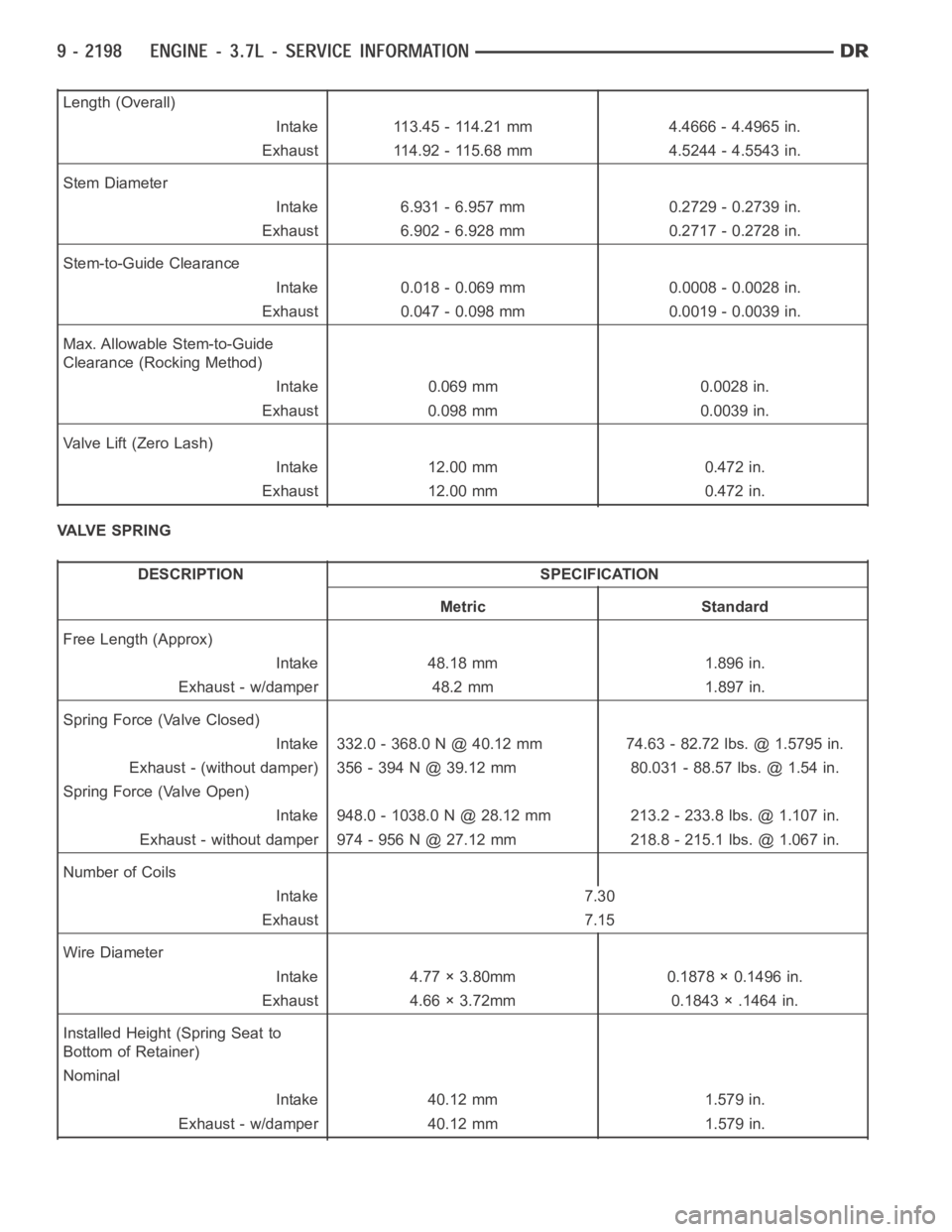
Length (Overall)
Intake 113.45 - 114.21 mm 4.4666 - 4.4965 in.
Exhaust 114.92 - 115.68 mm 4.5244 - 4.5543 in.
Stem Diameter
Intake 6.931 - 6.957 mm 0.2729 - 0.2739 in.
Exhaust 6.902 - 6.928 mm 0.2717 - 0.2728 in.
Stem-to-Guide Clearance
Intake 0.018 - 0.069 mm 0.0008 - 0.0028 in.
Exhaust 0.047 - 0.098 mm 0.0019 - 0.0039 in.
Max. Allowable Stem-to-Guide
Clearance (Rocking Method)
Intake 0.069 mm 0.0028 in.
Exhaust 0.098 mm 0.0039 in.
Valve Lift (Zero Lash)
Intake 12.00 mm 0.472 in.
Exhaust 12.00 mm 0.472 in.
VALVE SPRING
DESCRIPTION SPECIFICATION
Metric Standard
Free Length (Approx)
Intake 48.18 mm 1.896 in.
Exhaust - w/damper 48.2 mm 1.897 in.
Spring Force (Valve Closed)
Intake 332.0 - 368.0 N @ 40.12 mm 74.63 - 82.72 lbs. @ 1.5795 in.
Exhaust - (without damper) 356 - 394 N @ 39.12 mm 80.031 - 88.57 lbs. @ 1.54 in.
Spring Force (Valve Open)
Intake 948.0 - 1038.0 N @ 28.12 mm 213.2 - 233.8 lbs. @ 1.107 in.
Exhaust - without damper 974 - 956 N @ 27.12 mm 218.8 - 215.1 lbs. @ 1.067 in.
Number of Coils
Intake 7.30
Exhaust 7.15
Wire Diameter
Intake 4.77 × 3.80mm 0.1878 × 0.1496 in.
Exhaust 4.66 × 3.72mm 0.1843 × .1464 in.
Installed Height (Spring Seat to
Bottom of Retainer)
Nominal
Intake 40.12 mm 1.579 in.
Exhaust - w/damper 40.12 mm 1.579 in.
Page 1529 of 5267
REMOVAL
NOTE: The cylinder heads must be removed in
order to perform this procedure.
1. Remove rocker arms and lash adjusters (Refer to 9
- ENGINE/CYLINDER HEAD/ROCKER ARM /
ADJUSTER ASSY - REMOVAL).
2. Remove the camshaft bearing caps and the cam-
shaft.
NOTE: All valve springs and valves are removed in
the same manner; this procedure only covers one
valve and valve spring.
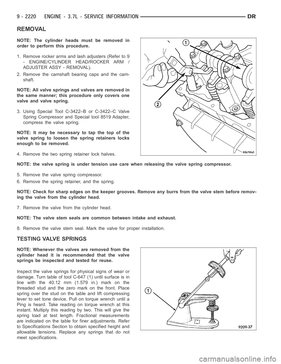
3. Using Special Tool C-3422–B or C-3422–C Valve
Spring Compressor and Special tool 8519 Adapter,
compress the valve spring.
NOTE: It may be necessary to tap the top of the
valve spring to loosen the spring retainers locks
enough to be removed.
4. Remove the two spring retainer lock halves.
NOTE: the valve spring is under tension use care when releasing the valve spring compressor.
5. Remove the valve spring compressor.
6. Remove the spring retainer, and the spring.
NOTE: Check for sharp edges on the keeper grooves. Remove any burrs from thevalvestembeforeremov-
ing the valve from the cylinder head.
7. Remove the valve from the cylinder head.
NOTE: The valve stem seals are common between intake and exhaust.
8. Remove the valve stem seal. Mark the valve for proper installation.
TESTING VALVE SPRINGS
NOTE: Whenever the valves are removed from the
cylinder head it is recommended that the valve
springs be inspected and tested for reuse.
Inspect the valve springs for physical signs of wear or
damage. Turn table of tool C-647 (1) until surface is in
line with the 40.12 mm (1.579 in.) mark on the
threaded stud and the zero mark on the front. Place
spring over the stud on the table and lift compressing
lever to set tone device. Pull on torque wrench until a
Ping is heard. Take reading on torque wrench at this
instant. Multiply this reading by two. This will give the
spring load at test length. Fractional measurements
are indicated on the table for finer adjustments. Refer
to Specifications Section to obtain specified height and
allowable tensions. Replace any springs that do not
meet specifications.
Page 1643 of 5267
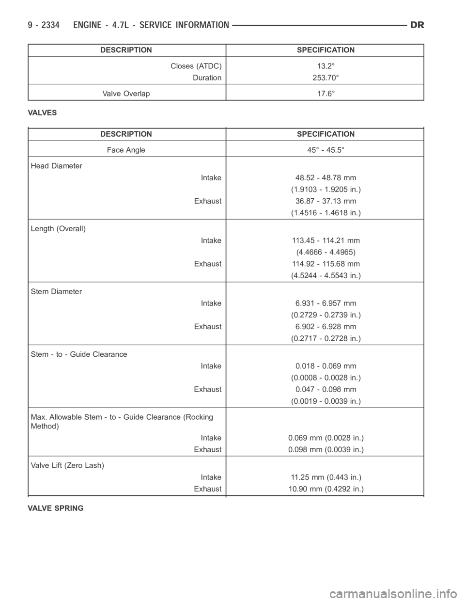
DESCRIPTION SPECIFICATION
Closes (ATDC) 13.2°
Duration 253.70°
Valve Overlap 17.6°
VA LV E S
DESCRIPTION SPECIFICATION
Face Angle 45° - 45.5°
Head Diameter
Intake 48.52 - 48.78 mm
(1.9103 - 1.9205 in.)
Exhaust 36.87 - 37.13 mm
(1.4516 - 1.4618 in.)
Length (Overall)
Intake 113.45 - 114.21 mm
(4.4666 - 4.4965)
Exhaust 114.92 - 115.68 mm
(4.5244 - 4.5543 in.)
Stem Diameter
Intake 6.931 - 6.957 mm
(0.2729 - 0.2739 in.)
Exhaust 6.902 - 6.928 mm
(0.2717 - 0.2728 in.)
Stem - to - Guide Clearance
Intake 0.018 - 0.069 mm
(0.0008 - 0.0028 in.)
Exhaust 0.047 - 0.098 mm
(0.0019 - 0.0039 in.)
Max. Allowable Stem - to - Guide Clearance (Rocking
Method)
Intake 0.069 mm (0.0028 in.)
Exhaust 0.098 mm (0.0039 in.)
Va l v e L i f t ( Z e r o L a s h )
Intake 11.25 mm (0.443 in.)
Exhaust 10.90 mm (0.4292 in.)
VALVE SPRING
Page 1644 of 5267
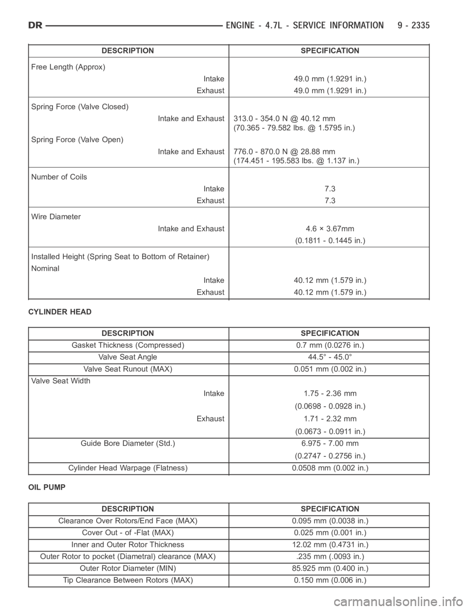
DESCRIPTION SPECIFICATION
Free Length (Approx)
Intake 49.0 mm (1.9291 in.)
Exhaust 49.0 mm (1.9291 in.)
Spring Force (Valve Closed)
Intake and Exhaust 313.0 - 354.0 N @ 40.12 mm
(70.365 - 79.582 lbs. @ 1.5795 in.)
Spring Force (Valve Open)
Intake and Exhaust 776.0 - 870.0 N @ 28.88 mm
(174.451 - 195.583 lbs. @ 1.137 in.)
Number of Coils
Intake 7.3
Exhaust 7.3
Wire Diameter
Intake and Exhaust 4.6 × 3.67mm
(0.1811 - 0.1445 in.)
Installed Height (Spring Seat to Bottom of Retainer)
Nominal
Intake 40.12 mm (1.579 in.)
Exhaust 40.12 mm (1.579 in.)
CYLINDER HEAD
DESCRIPTION SPECIFICATION
Gasket Thickness (Compressed) 0.7 mm (0.0276 in.)
Valve Seat Angle 44.5° - 45.0°
Valve Seat Runout (MAX) 0.051 mm (0.002 in.)
Va l v e S e a t W i d t h
Intake 1.75 - 2.36 mm
(0.0698 - 0.0928 in.)
Exhaust 1.71 - 2.32 mm
(0.0673 - 0.0911 in.)
Guide Bore Diameter (Std.) 6.975 - 7.00 mm
(0.2747 - 0.2756 in.)
Cylinder Head Warpage (Flatness) 0.0508 mm (0.002 in.)
OIL PUMP
DESCRIPTION SPECIFICATION
Clearance Over Rotors/End Face (MAX) 0.095 mm (0.0038 in.)
Cover Out - of -Flat (MAX) 0.025 mm (0.001 in.)
Inner and Outer Rotor Thickness 12.02 mm (0.4731 in.)
Outer Rotor to pocket (Diametral) clearance (MAX) .235 mm (.0093 in.)
Outer Rotor Diameter (MIN) 85.925 mm (0.400 in.)
Tip Clearance Between Rotors (MAX) 0.150 mm (0.006 in.)
Page 1681 of 5267
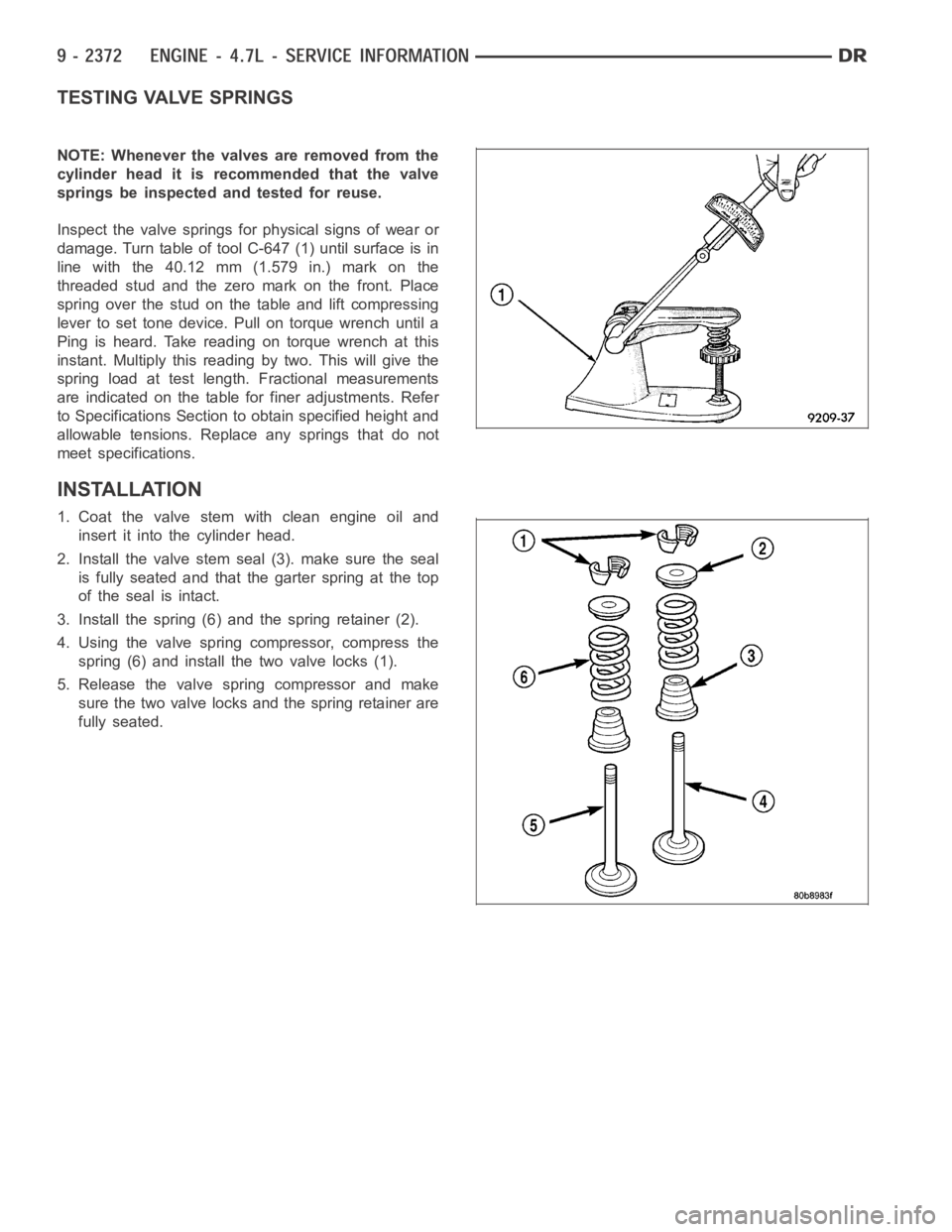
TESTING VALVE SPRINGS
NOTE: Whenever the valves are removed from the
cylinder head it is recommended that the valve
springs be inspected and tested for reuse.
Inspect the valve springs for physical signs of wear or
damage. Turn table of tool C-647 (1) until surface is in
line with the 40.12 mm (1.579 in.) mark on the
threaded stud and the zero mark on the front. Place
spring over the stud on the table and lift compressing
lever to set tone device. Pull on torque wrench until a
Ping is heard. Take reading on torque wrench at this
instant. Multiply this reading by two. This will give the
spring load at test length. Fractional measurements
are indicated on the table for finer adjustments. Refer
to Specifications Section to obtain specified height and
allowable tensions. Replace any springs that do not
meet specifications.
INSTALLATION
1. Coat the valve stem with clean engine oil and
insert it into the cylinder head.
2. Install the valve stem seal (3). make sure the seal
is fully seated and that the garter spring at the top
of the seal is intact.
3. Install the spring (6) and the spring retainer (2).
4. Using the valve spring compressor, compress the
spring (6) and install the two valve locks (1).
5. Release the valve spring compressor and make
sure the two valve locks and the spring retainer are
fully seated.