2006 DODGE RAM SRT-10 tire type
[x] Cancel search: tire typePage 2086 of 5267
LUBRICATION
DESCRIPTION
The engine lubrication system is a full-flow filtration pressure feed type.
OPERATION
Engine oil stored in the oil pan is taken in and discharged by an internal geartypeoilpump,whichisdrivenbythe
crankshaft. A pressure relief valve is located in the timing chain case cover; it regulates oil pressure. The oil is
pumped through an oil filter and feeds a main oil gallery. Also, oil is routedtoanexternaloilcooler.Themainoil
gallery feeds oil under pressure to the main bearings, connecting rod bearings, and camshaft bearings. Passages in
the cylinder block feed oil to the hydraulic lifters. The oil then flows through hollow pushrods, which feed the rocker
arm pivots.
DIAGNOSIS AND TESTING
CHECKING ENGINE OIL PRESSURE
1. Remove oil pressure sensor (Refer to 9 - ENGINE/LUBRICATION/OIL PRESSURE SENSOR - REMOVAL).
2. Install oil pressure gauge.
3. Warm engine at high idle until thermostat opens.
CAUTION: If oil pressure is 0 at idle, Do Not Run engine at 3000 RPM.
4. Oil pressure should be 68.9 kPa (10 psi) at idle or 310 - 517 kPa (45 - 75 psi)at 3000 RPM.
5. If oil pressure is 0 at idle, shut off engine. Check for a clogged oil pick-up screen or a pressure relief valve stuck
open.
ENGINE OIL LEAK
Begin with a thorough visual inspection of the engine, particularly at thearea of the suspected leak. If an oil leak
source is not readily identifiable, thefollowingstepsshouldbefollowed:
1. Do not clean or degrease the engine at this time because some solvents maycause rubber to swell, temporarily
stopping the leak.
2. Add an oil soluble dye (use as recommended by manufacturer). Start the engine and let idle for approximately 15
minutes. Check the oil dipstick to make sure the dye is thoroughly mixed as indicated with a bright yellow color
under a black light.
3. Using a black light, inspect the entire engine for fluorescent dye, particularly at the suspected area of oil leak. If
the oil leak is found and identified, repair per service manual instructions.
4. If dye is not observed, drive the vehicle at various speeds for approximately 24 km (15 miles), and repeat inspec-
tion.If the oil leak source is not positively identified at this time, proceed with the air leak detection test
method.
Air Leak Detection Test Method
1. Remove the PCV valve from the IAFM. Cap or plug the PCV valve grommet.
2. Attach an air hose with pressure gauge and regulator to the dipstick tube.
CAUTION: Do not subject the engine assembly to more than 20.6 kPa (3 PSI) of test pressure.
3. Gradually apply air pressure from 6.89 - 17.23 kPa (1 - 2.5 psi) maximum while applying soapy water at the
suspected source. Adjust the regulator to the suitable test pressure thatprovide the best bubbles which will pin-
point the leak source. If the oil leak is detected and identified, repair per service manual procedures.
4. If the leakage occurs at the rear oil seal area, refer to the section, Inspection for Rear Seal Area Leak.
5. If no leaks are detected, turn off the air supply and remove the air hose and all plugs and caps. Install the PCV
valve.
6. Clean the oil off the suspect oil leak area using a suitable solvent. Drive the vehicle at various speeds approx-
imately 24 km (15 miles). Inspect the engine for signs of an oil leak by usinga black light.
Page 2204 of 5267
CAUTION: Do not use any flame or plasma cutting equipment to cut the frame inthis procedure. The inac-
curate and high temperatures achieved during flame or plasma cutting willchange the metal characteristics
and may weaken the frame and/or repair location.
12. Carefully remove the H-section welds using a grinder or equivalent tool.
13. Remove the H-section and clean any remaining welds from the frame.
14. Trial fit the replacement part.
15. Remove all e-coat from within 25 mm (1.0 in.) of the weld area.
16. Using the appropriate measuring equipment, position the replacementpart and verify correct positioning in all
three (X,Y, and Z) planes of space. (Refer to 13 - FRAME & BUMPERS/FRAME - SPECIFICATIONS - FRAME
DIMENSIONS)
CAUTION: Shield the surrounding area and components from exposure to the welding spatter and heat.
17. Weld the replacement H-section into position. The welding should be performedinaskip(stitch)typemethod
to minimize the heat buildup followingI-CAR or the American Welding Society welding procedures and utilizing
the process specifications at the end of this section. (Refer to 13 - FRAME &BUMPERS/FRAME - SPECIFI-
CATIONS - WELDING)
18. Dress the welded area and apply corrosion resistant coatings inside and out.
a. Inside the rail, inject a creeping wax based rust inhibitor compound through the existing holes in the frame
ensuring 100% coverage including the mating face between the frame and replacement H-section.
b. Apply a durable top coat to the outside of the repair area.
19. Position the wiring harness back.
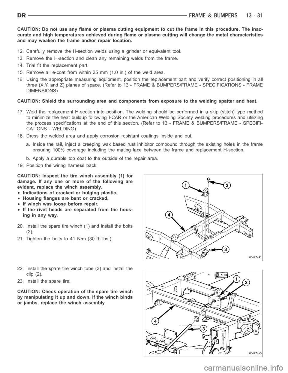
CAUTION: Inspect the tire winch assembly (1) for
damage. If any one or more of the following are
evident, replace the winch assembly.
Indications of cracked or bulging plastic.
Housing flanges are bent or cracked.
If winch was loose before repair.
If the rivet heads are separated from the hous-
inginanyway.
20. Install the spare tire winch (1) and install the bolts
(2).
21. Tightentheboltsto41Nꞏm(30ft.lbs.).
22. Install the spare tire winch tube (3) and install the
clip (2).
23. Install the spare tire.
CAUTION: Check operation of the spare tire winch
by manipulating it up and down. If the winch binds
or jambs, replace the winch assembly.
Page 3940 of 5267
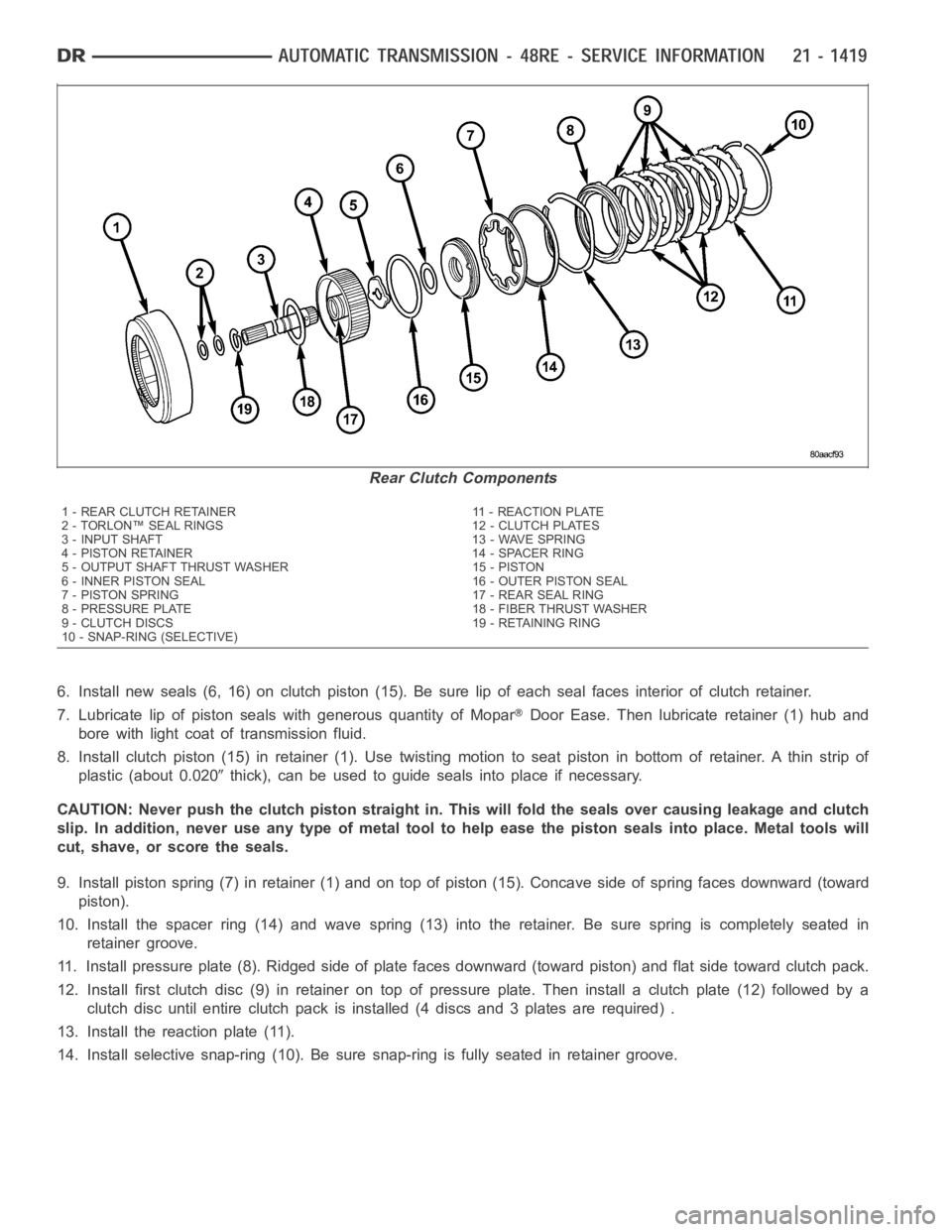
6. Install new seals (6, 16) on clutch piston (15). Be sure lip of each seal faces interior of clutch retainer.
7. Lubricate lip of piston seals with generous quantity of Mopar
Door Ease. Then lubricate retainer (1) hub and
bore with light coat of transmission fluid.
8. Install clutch piston (15) in retainer (1). Use twisting motion to seat piston in bottom of retainer. A thin strip of
plastic (about 0.020
thick), can be used to guide seals into place if necessary.
CAUTION: Never push the clutch piston straight in. This will fold the sealsover causing leakage and clutch
slip. In addition, never use any type of metal tool to help ease the piston seals into place. Metal tools will
cut, shave, or score the seals.
9. Install piston spring (7) in retainer (1) and on top of piston (15). Concave side of spring faces downward (toward
piston).
10. Install the spacer ring (14) and wave spring (13) into the retainer. Be sure spring is completely seated in
retainer groove.
11. Install pressure plate (8). Ridged side of plate faces downward (toward piston) and flat side toward clutch pack.
12. Install first clutch disc (9) in retainer on top of pressure plate. Theninstall a clutch plate (12) followed by a
clutch disc until entire clutch pack is installed (4 discs and 3 plates are required) .
13. Install the reaction plate (11).
14. Install selective snap-ring (10). Be sure snap-ring is fully seated inretainer groove.
Rear Clutch Components
1 - REAR CLUTCH RETAINER 11 - REACTION PLATE
2 - TORLON™ SEAL RINGS 12 - CLUTCH PLATES
3 - INPUT SHAFT 13 - WAVE SPRING
4 - PISTON RETAINER 14 - SPACER RING
5 - OUTPUT SHAFT THRUST WASHER 15 - PISTON
6 - INNER PISTON SEAL 16 - OUTER PISTON SEAL
7 - PISTON SPRING 17 - REAR SEAL RING
8 - PRESSURE PLATE 18 - FIBER THRUST WASHER
9 - CLUTCH DISCS 19 - RETAINING RING
10 - SNAP-RING (SELECTIVE)
Page 4179 of 5267
DIAGNOSIS AND TESTING - TRANSFER CASE - NV243
DIAGNOSIS CHART
Condition Possible Cause Correction
Transfer case difficult to shift or will
not shift into desired range.1) Transfer case electronically
controlled shift system malfunction.1) Verify proper operation per the
appropriate diagnostic manual.
2) If vehicle was operated for an
extended period in 4HI mode on dry
surface, driveline torque load may
cause difficulty.2) Drive the vehicle in a straight line
and momentarily release the
accelerator. The transfer case can
then be shifted to the desired mode.
3) Insufficient or incorrect lubricant. 3) Drain and refill transfer casewith
the correct quantity of Mopar
AT F
+4, Automatic Transmission Fluid.
4) Internal transfer case
components binding, worn, or
damaged.4) Repair or replace components as
necessary.
Transfer case noisy in all drive
modes.1) Insufficient or incorrect lubricant. 1) Drain and refill transfer casewith
the correct quantity of Mopar
AT F
+4, type 9602, Automatic
Transmission Fluid.
2) Internal transfer case
components binding, worn, or
damaged.2) Repair or replace components as
necessary.
Transfer case noisy while in, or
jumps out of, 4LO mode.1) Transfer case not completely
engaged in 4LO position.1) While rolling 2-3 MPH and the
transmission in NEUTRAL, or clutch
depressed on vehicles equipped
with a manual transmission, shift
transfer case to the 2WD or 4HI
position, and then back into the 4LO
position.
2) Range fork damaged, inserts
worn, or fork is binding on the shift
rail.2) Repair or replace components as
necessary.
3) Low range gear worn or
damaged.3) Repair or replace components as
necessary.
Lubricant leaking from transfer case
seals or vent.1) Transfer case overfilled. 1) Drain lubricant to the correct
level.
2) Transfer case vent closed or
restricted.2) Clean or replace vent as
necessary.
3) Transfer case seals damaged or
installed incorrectly.3) Replace suspect seal.
Abnormal tire wear. 1) Extended operation in 4HI mode
on dry surfaces,1) Operate vehicle in 2WD mode on
dry surfaces.
Page 4266 of 5267
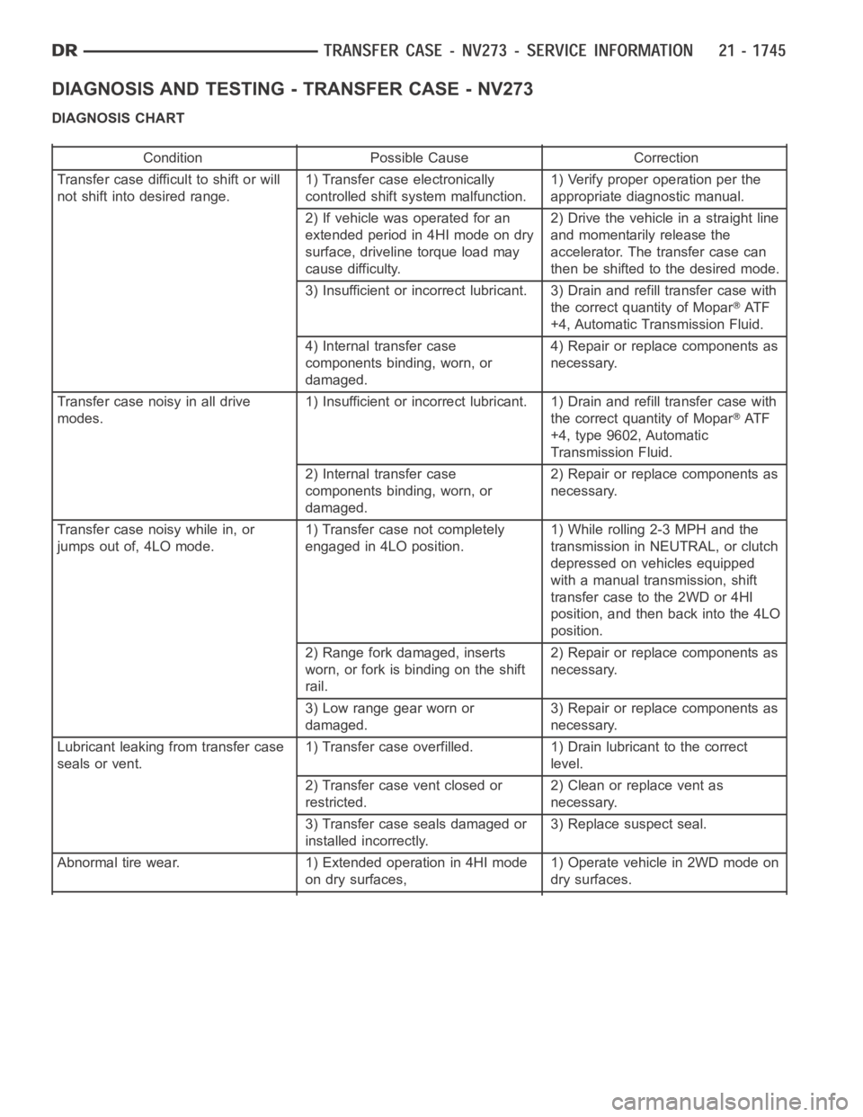
DIAGNOSIS AND TESTING - TRANSFER CASE - NV273
DIAGNOSIS CHART
Condition Possible Cause Correction
Transfer case difficult to shift or will
not shift into desired range.1) Transfer case electronically
controlled shift system malfunction.1) Verify proper operation per the
appropriate diagnostic manual.
2) If vehicle was operated for an
extended period in 4HI mode on dry
surface, driveline torque load may
cause difficulty.2) Drive the vehicle in a straight line
and momentarily release the
accelerator. The transfer case can
then be shifted to the desired mode.
3) Insufficient or incorrect lubricant. 3) Drain and refill transfer casewith
the correct quantity of Mopar
AT F
+4, Automatic Transmission Fluid.
4) Internal transfer case
components binding, worn, or
damaged.4) Repair or replace components as
necessary.
Transfer case noisy in all drive
modes.1) Insufficient or incorrect lubricant. 1) Drain and refill transfer casewith
the correct quantity of Mopar
AT F
+4, type 9602, Automatic
Transmission Fluid.
2) Internal transfer case
components binding, worn, or
damaged.2) Repair or replace components as
necessary.
Transfer case noisy while in, or
jumps out of, 4LO mode.1) Transfer case not completely
engaged in 4LO position.1) While rolling 2-3 MPH and the
transmission in NEUTRAL, or clutch
depressed on vehicles equipped
with a manual transmission, shift
transfer case to the 2WD or 4HI
position, and then back into the 4LO
position.
2) Range fork damaged, inserts
worn, or fork is binding on the shift
rail.2) Repair or replace components as
necessary.
3) Low range gear worn or
damaged.3) Repair or replace components as
necessary.
Lubricant leaking from transfer case
seals or vent.1) Transfer case overfilled. 1) Drain lubricant to the correct
level.
2) Transfer case vent closed or
restricted.2) Clean or replace vent as
necessary.
3) Transfer case seals damaged or
installed incorrectly.3) Replace suspect seal.
Abnormal tire wear. 1) Extended operation in 4HI mode
on dry surfaces,1) Operate vehicle in 2WD mode on
dry surfaces.
Page 4321 of 5267
TIRES
DESCRIPTION
TIRES
Tires are designed and engineered for each specific vehicle. They providethe best overall performance for normal
operation. The ride and handling characteristics match the vehicle’s requirements. With proper care they will give
excellent reliability, traction,skid resistance, and tread life.
Driving habits have more effect on tire life than any other factor. Carefuldrivers will obtain in most cases, much
greater mileage than severe use or careless drivers. A few of the driving habits which will shorten the life of any tire
are:
Rapid acceleration
Severe brake applications
High speed driving
Excessive speeds on turns
Striking curbs and other obstacles
Radial-ply tires are more prone to irregular tread wear. It is important tofollow the tire rotation interval (Refer to 22
- TIRES/WHEELS - STANDARD PROCEDURE). This will help to achieve a greater tread life.
TIRE IDENTIFICATION
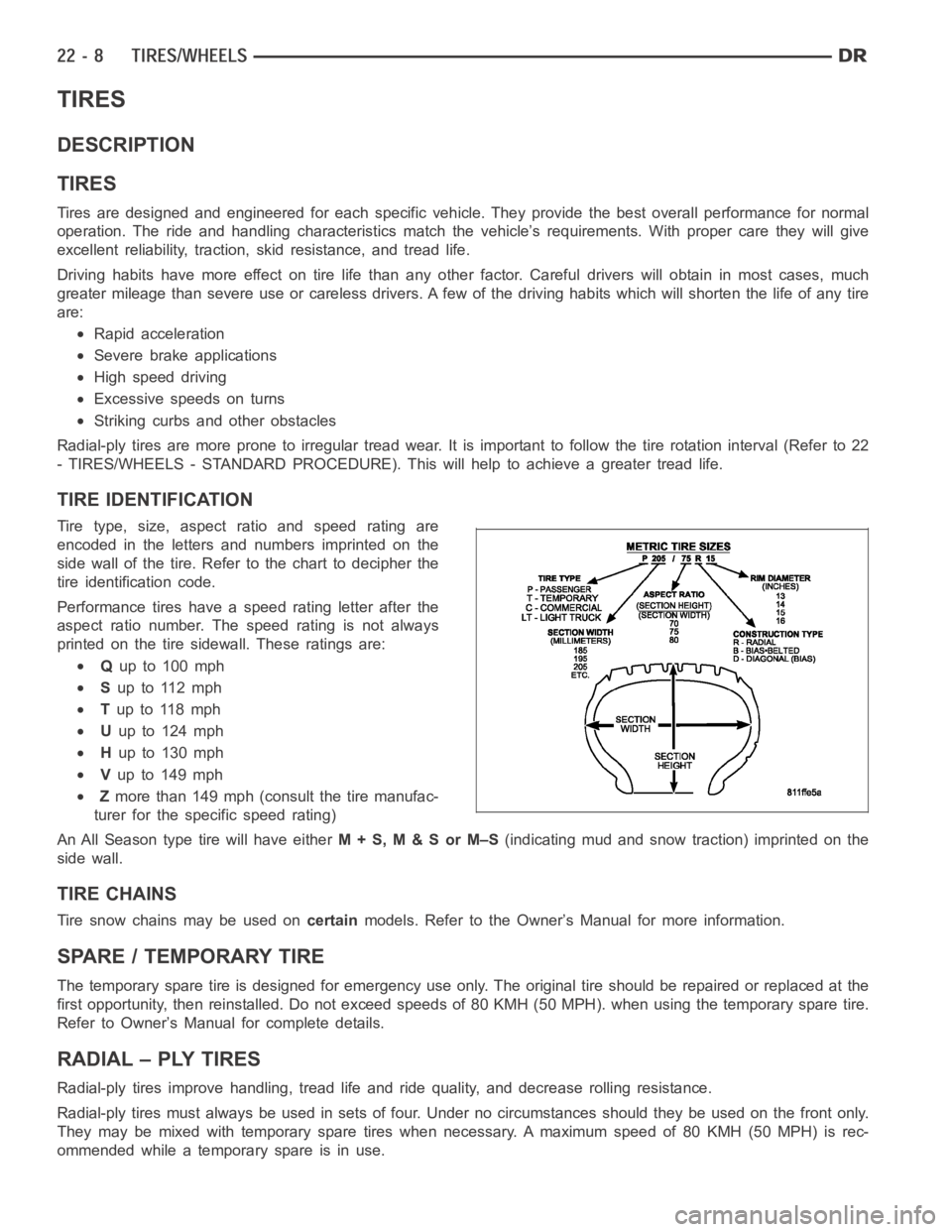
Tire type, size, aspect ratio and speed rating are
encoded in the letters and numbers imprinted on the
side wall of the tire. Refer to the chart to decipher the
tire identification code.
Performance tires have a speed rating letter after the
aspect ratio number. The speed rating is not always
printed on the tire sidewall. These ratings are:
Qup to 100 mph
Sup to 112 mph
Tup to 118 mph
Uup to 124 mph
Hup to 130 mph
Vup to 149 mph
Zmore than 149 mph (consult the tire manufac-
turer for the specific speed rating)
An All Season type tire will have eitherM+S,M&SorM–S(indicating mud and snow traction) imprinted on the
side wall.
TIRE CHAINS
Tire snow chains may be used oncertainmodels. Refer to the Owner’s Manual for more information.
SPARE / TEMPORARY TIRE
The temporary spare tire is designed for emergency use only. The original tire should be repaired or replaced at the
first opportunity, then reinstalled. Do not exceed speeds of 80 KMH (50 MPH). when using the temporary spare tire.
Refer to Owner’s Manual for complete details.
RADIAL – PLY TIRES
Radial-ply tires improve handling, tread life and ride quality, and decrease rolling resistance.
Radial-ply tires must always be used in sets of four. Under no circumstances should they be used on the front only.
They may be mixed with temporary spare tires when necessary. A maximum speedof80KMH(50MPH)isrec-
ommended while a temporary spare is in use.
Page 4322 of 5267
Radial-ply tires have the same load-carrying capacity as other types of tires of the same size. They also use the
same recommended inflation pressures.
The use of oversized tires, either in the front or rear of the vehicle, can cause vehicle drive train failure. This could
also cause inaccurate wheel speed signals when the vehicle is equipped with Anti-Lock Brakes.
The use of tires from different manufactures on the same vehicle is NOT recommended. The proper tire pressure
should be maintained on all four tires.
TIRE PRESSURE FOR HIGH SPEEDS
For proper tire pressure specification refer to the Owners Manual.
REPLACEMENT TIRES
The original equipment tires provide a proper balance of many characteristics such as:
Ride
Noise
Handling
Durability
Tread life
Traction
Rolling resistance
Speed capability
It is recommended that tires equivalent to the original equipment tires beused when replacement is needed.
Failure to use equivalent replacement tires may adversely affect the safety and handling of the vehicle.
The use of oversize tires may cause interference with vehicle components.Under extremes of suspension and
steering travel, interference with vehicle components may cause tire damage.
WARNING: Failure to equip the vehicle with tires having adequate speed capability can result in sudden tire
failure.
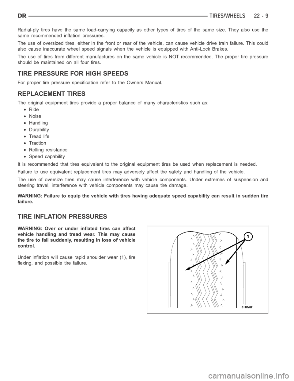
TIRE INFLATION PRESSURES
WARNING: Over or under inflated tires can affect
vehicle handling and tread wear. This may cause
the tire to fail suddenly, resulting in loss of vehicle
control.
Under inflation will cause rapid shoulder wear (1), tire
flexing, and possible tire failure.
Page 4346 of 5267
PANEL REINFORCEMENT
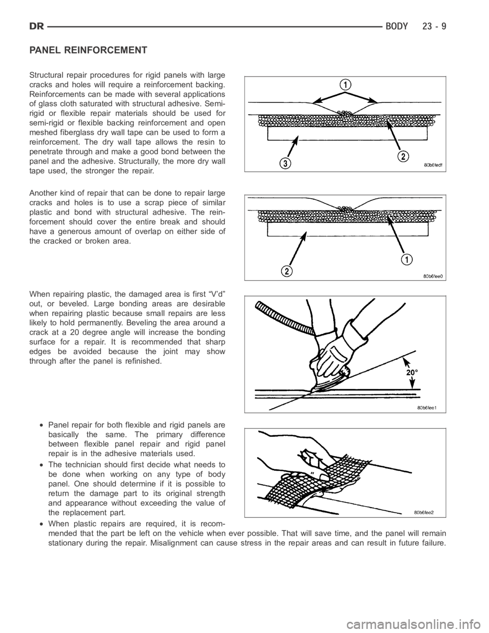
Structural repair procedures for rigid panels with large
cracks and holes will require a reinforcement backing.
Reinforcements can be made with several applications
of glass cloth saturated with structural adhesive. Semi-
rigid or flexible repair materials should be used for
semi-rigid or flexible backing reinforcement and open
meshed fiberglass dry wall tape can be used to form a
reinforcement. The dry wall tape allows the resin to
penetrate through and make a good bond between the
panel and the adhesive. Structurally, the more dry wall
tape used, the stronger the repair.
Another kind of repair that can be done to repair large
cracks and holes is to use a scrap piece of similar
plastic and bond with structural adhesive. The rein-
forcement should cover the entire break and should
have a generous amount of overlap on either side of
thecrackedorbrokenarea.
When repairing plastic, the damaged area is first “V’d”
out, or beveled. Large bonding areas are desirable
when repairing plastic because small repairs are less
likely to hold permanently. Beveling the area around a
crack at a 20 degree angle will increase the bonding
surface for a repair. It is recommended that sharp
edges be avoided because the joint may show
through after the panel is refinished.
Panel repair for both flexible and rigid panels are
basically the same. The primary difference
between flexible panel repair and rigid panel
repair is in the adhesive materials used.
The technician should first decide what needs to
be done when working on any type of body
panel. One should determine if it is possible to
return the damage part to its original strength
and appearance without exceeding the value of
the replacement part.
When plastic repairs are required, it is recom-
mended that the part be left on the vehicle when ever possible. That will save time, and the panel will remain
stationary during the repair. Misalignment can cause stress in the repairareas and can result in future failure.