2006 DODGE RAM SRT-10 fold seats
[x] Cancel search: fold seatsPage 1521 of 5267
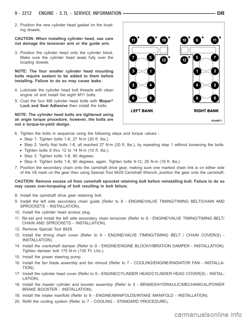
2. Position the new cylinder head gasket on the locat-
ing dowels.
CAUTION: When installing cylinder head, use care
not damage the tensioner arm or the guide arm.
3. Position the cylinder head onto the cylinder block.
Make sure the cylinder head seats fully over the
locating dowels.
NOTE: The four smaller cylinder head mounting
bolts require sealant to be added to them before
installing. Failure to do so may cause leaks.
4. Lubricate the cylinder head bolt threads with clean
engine oil and install the eight M11 bolts.
5. Coat the four M8 cylinder head bolts withMopar
Lock and Seal Adhesivethen install the bolts.
NOTE: The cylinder head bolts are tightened using
an angle torque procedure, however, the bolts are
not a torque-to-yield design.
6. Tighten the bolts in sequence using the following steps and torque values:
Step 1: Tighten bolts 1-8, 27 Nꞏm (20 ft. lbs.).
Step 2: Verify that bolts 1-8, all reached 27 Nꞏm (20 ft. lbs.), by repeatingstep 1 without loosening the bolts.
Tightenbolts9thru12to14Nꞏm(10ft.lbs.).
Step 3: Tighten bolts 1-8, 90 degrees.
Step 4: Tighten bolts 1-8, 90 degrees, again. Tighten bolts 9-12, 26 Nꞏm (19ft. lbs.)
7. Position the secondary chain onto the camshaft drive gear, making sure one marked chain link is on either side
of the V6 mark on the gear then using Special Tool 8428 Camshaft Wrench, position the gear onto the camshaft.
CAUTION: Remove excess oil from camshaft sprocket retaining bolt before reinstalling bolt. Failure to do so
may cause over-torqueing of bolt resulting in bolt failure.
8. Install the camshaft drive gear retaining bolt.
9. Install the left side secondary chain guide (Refer to 9 - ENGINE/VALVE TIMING/TIMING BELT/CHAIN AND
SPROCKETS - INSTALLATION).
10. Install the cylinder head access plug.
11. Re-set and install the left side secondary chain tensioner (Refer to 9 -ENGINE/VALVE TIMING/TIMING BELT/
CHAIN AND SPROCKETS - INSTALLATION).
12. Remove Special Tool 8429.
13. Install the timing chain cover (Refer to 9 - ENGINE/VALVE TIMING/TIMING BELT / CHAIN COVER(S) -
INSTALLATION).
14. Install the crankshaft damper (Refer to 9 - ENGINE/ENGINE BLOCK/VIBRATION DAMPER - INSTALLATION).
Tighten damper bolt 175 Nꞏm (130 Ft. Lbs.).
15. Install the power steering pump.
16. Install the fan blade assembly and fan shroud (Refer to 7 - COOLING/ENGINE/RADIATOR FAN - INSTALLA-
TION).
17. Install the cylinder head cover (Refer to 9 - ENGINE/CYLINDER HEAD/CYLINDER HEAD COVER(S) - INSTAL-
LATION).
18. Install the master cylinder and booster assembly (Refer to 5 - BRAKES/HYDRAULIC/MECHANICAL/POWER
BRAKE BOOSTER - INSTALLATION).
19. Install the intake manifold (Refer to 9 - ENGINE/MANIFOLDS/INTAKE MANIFOLD - INSTALLATION).
20. Refill the cooling system (Refer to 7 - COOLING - STANDARD PROCEDURE).
Page 1910 of 5267

EXCESSIVE WHITE SMOKE
POSSIBLE CAUSE CORRECTION
Fuel filter plugged. Refer to Powertrain Diagnostic Manual for fuel system
testing.
Fuel grade not correct or fuel quality is poor. Temporarily change fuel brands and note condition.
Change brand if necessary.
Fuel heater element or fuel heater temperature sensor
malfunctioning. This will cause wax type build-up in fuel
filter.Refer to Fuel Heater Testing (Refer to 14 - FUEL
SYSTEM/FUEL DELIVERY/FUEL HEATER -
DIAGNOSIS AND TESTING).
Fuel injector malfunctioning. A DTC should have been set. Perform “Cylinder
Performance Test
orCylinder cutout Testusing DRB
scan tool to isolate individual cylinders. Also refer to
Powertrain Diagnostic Procedures Information and,
(Refer to 14 - FUEL SYSTEM/FUEL INJECTION/FUEL
INJECTOR - DIAGNOSIS AND TESTING).
Fuel injector hold-downs loose. Torque to specifications.
Fuel injector protrusion not correct. Check washer (shim) at bottom of fuel injector for
correct thickness. (Referto 14 - FUEL SYSTEM/FUEL
INJECTION/FUEL INJECTOR - INSTALLATION)
Fuel injection pump malfunctioning. A DTC should have been set. Refer to Powertrain
Diagnostic Procedures Information.
Fuel supply side restriction. Refer to Powertrain Diagnostic Manual for fuel system
testing.
Fuel transfer (lift) pump malfunctioning. A DTC may have been set. Refer toPowertrain
Diagnostic Procedures Information.
Intake/Exhaust valve adjustments not correct (too tight). (Refer to 9 - ENGINE/CYLINDER HEAD/INTAKE/
EXHAUST VALVES & SEATS - STANDARD
PROCEDURE).
Intake manifold air temperature sensor malfunctioning. A DTC should havebeen set. Refer to Powertrain
Diagnostic Procedures Information.
Intake manifold heater circuit not functioning correctly in
cold weather.A DTC should have been set. Refer to Powertrain
Diagnostic Procedures Information. Also check heater
elements for correct operation.
Intake manifold heater elements not functioning
correctly in cold weather.A DTC should have been set if heater elements are
malfunctioning. Refer to Powertrain Diagnostic
Procedures Information.
Internal engine damage (scuffed cylinder). Analyze engine oil and inspect oil filter to locate area of
probable damage.
Restriction in fuel supply side of fuel system. Refer to Powertrain Diagnostic Manual for fuel system
testing.
EXCESSIVE BLUE SMOKE
POSSIBLE CAUSE CORRECTION
Dirty air cleaner or restricted turbocharger intake duct. Check Filter Minder
at air filter housing. (Refer to 9 -
ENGINE/AIR INTAKE SYSTEM/AIR CLEANER
ELEMENT - REMOVAL).
Air leak in boost system between turbocharger
compressor outlet and intake manifold.Service air charge system..
Obstruction in exhaust manifold. Remove exhaust manifold and inspect forblockage
(Refer to 9 - ENGINE/MANIFOLDS/EXHAUST
MANIFOLD - REMOVAL).
Page 2020 of 5267
page page
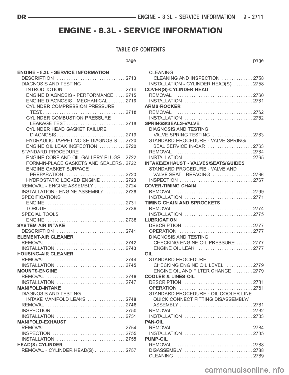
ENGINE - 8.3L - SERVICE INFORMATION
DESCRIPTION ............................. 2713
DIAGNOSIS AND TESTING
INTRODUCTION . ......................... 2714
ENGINE DIAGNOSIS - PERFORMANCE .... 2715
ENGINE DIAGNOSIS - MECHANICAL ....... 2716
CYLINDER COMPRESSION PRESSURE
TEST.................................... 2718
CYLINDER COMBUSTION PRESSURE
LEAKAGE TEST.......................... 2718
CYLINDER HEAD GASKET FAILURE
DIAGNOSIS.............................. 2719
HYDRAULIC TAPPET NOISE DIAGNOSIS . . . 2720
ENGINE OIL LEAK INSPECTION ........... 2720
STANDARD PROCEDURE
ENGINE CORE AND OIL GALLERY PLUGS . 2722
FORM-IN-PLACE GASKETS AND SEALERS . 2722
ENGINE GASKET SURFACE
PREPARATION........................... 2723
HYDROSTATIC LOCKED ENGINE .......... 2723
REMOVAL - ENGINE ASSEMBLY . . ........... 2724
INSTALLATION - ENGINE ASSEMBLY ........ 2728
SPECIFICATIONS
ENGINE ................................. 2731
TORQUE ................................. 2736
SPECIAL TOOLS
ENGINE ................................. 2738
SYSTEM-AIR INTAKE
DESCRIPTION ............................. 2741
ELEMENT-AIR CLEANER
REMOVAL ................................. 2742
INSTALLATION ............................. 2743
HOUSING-AIR CLEANER
REMOVAL ................................. 2744
INSTALLATION ............................. 2745
MOUNTS-ENGINE
REMOVAL ................................. 2746
INSTALLATION ............................. 2747
MANIFOLD-INTAKE
DIAGNOSIS AND TESTING
INTAKE MANIFOLD LEAKS ................ 2748
REMOVAL ................................. 2748
INSPECTION ............................... 2750
INSTALLATION ............................. 2751
MANIFOLD-EXHAUST
REMOVAL ................................. 2754
INSPECTION ............................... 2755
INSTALLATION ............................. 2755
HEAD(S)-CYLINDER
REMOVAL - CYLINDER HEAD(S) ............. 2757CLEANING
CLEANING AND INSPECTION............. 2758
INSTALLATION - CYLINDER HEAD(S) ........ 2758
COVER(S)-CYLINDER HEAD
REMOVAL ................................. 2760
INSTALLATION ............................. 2761
ARMS-ROCKER
REMOVAL ................................. 2762
INSTALLATION ............................. 2762
SPRINGS/SEALS-VALVE
DIAGNOSIS AND TESTING
VALVE SPRING TESTING ................. 2763
STANDARD PROCEDURE - VALVE SPRING/
SEAL SERVICE IN-CAR ................... 2763
REMOVAL ................................. 2764
INSTALLATION ............................. 2765
INTAKE/EXHAUST - VALVES/SEATS/GUIDES
STANDARD PROCEDURE - VALVE AND
VALVE SEAT - REFACING ................. 2766
INSPECTION............................... 2767
COVER-TIMING CHAIN
REMOVAL ................................. 2769
INSTALLATION ............................. 2771
TIMING CHAIN AND SPROCKETS
REMOVAL ................................. 2774
INSTALLATION ............................. 2775
LUBRICATION
DESCRIPTION ............................. 2777
OPERATION ............................... 2777
DIAGNOSIS AND TESTING
CHECKING ENGINE OIL PRESSURE ....... 2777
ENGINE OIL LEAK ........................ 2777
OIL
STANDARD PROCEDURE
CHECKING ENGINE OIL LEVEL........... 2779
ENGINE OILAND FILTER CHANGE ........ 2779
COOLER & LINES-OIL
DESCRIPTION ............................. 2781
OPERATION ............................... 2781
STANDARD PROCEDURE - OIL COOLER LINE
QUICK CONNECT FITTING DISASSEMBLY/
ASSEMBLY............................... 2781
REMOVAL ................................. 2782
INSTALLATION ............................. 2783
PAN-OIL
REMOVAL ................................. 2784
INSTALLATION ............................. 2785
PUMP-OIL
REMOVAL ................................. 2788
DISASSEMBLY . ............................ 2788
CLEANING ................................. 2789
Page 2025 of 5267
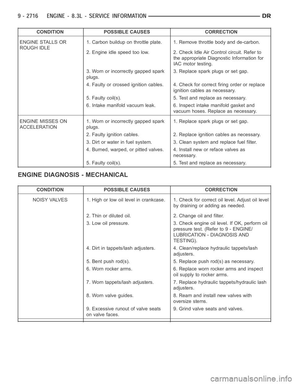
CONDITION POSSIBLE CAUSES CORRECTION
ENGINE STALLS OR
ROUGH IDLE1. Carbon buildup on throttle plate. 1. Remove throttle body and de-carbon.
2. Engine idle speed too low. 2. Check Idle Air Control circuit. Refer to
the appropriate Diagnostic Information for
IAC motor testing.
3. Worn or incorrectly gapped spark
plugs.3. Replace spark plugs or set gap.
4. Faulty or crossed ignition cables. 4. Check for correct firing order or replace
ignition cables as necessary.
5. Faulty coil(s). 5. Test and replace as necessary.
6. Intake manifold vacuum leak. 6. Inspect intake manifold gasket and
vacuum hoses. Replace as necessary.
ENGINE MISSES ON
ACCELERATION1. Worn or incorrectly gapped spark
plugs.1. Replace spark plugs or set gap.
2. Faulty ignition cables. 2. Replace ignition cables as necessary.
3. Dirt or water in fuel system. 3. Clean system and replace fuel filter.
4. Burned, warped, or pitted valves. 4. Install new or reface valves as
necessary.
5. Faulty coil(s). 5. Test and replace as necessary.
ENGINE DIAGNOSIS - MECHANICAL
CONDITION POSSIBLE CAUSES CORRECTION
NOISY VALVES 1. High or low oil level incrankcase. 1. Check for correct oil level. Adjust oil level
by draining or adding as needed.
2. Thin or diluted oil. 2. Change oil and filter.
3. Low oil pressure. 3. Check engine oil level. If OK, perform oil
pressure test. (Refer to 9 - ENGINE/
LUBRICATION - DIAGNOSIS AND
TESTING).
4. Dirt in tappets/lash adjusters. 4. Clean/replace hydraulic tappets/lash
adjusters.
5. Bent push rod(s). 5. Replace push rod(s) as necessary.
6. Worn rocker arms. 6. Replace worn rocker arms and inspect
oil supply to rocker arms.
7. Worn tappets/lash adjusters. 7. Replace hydraulic tappets/hydrauliclash
adjusters.
8. Worn valve guides. 8. Ream and install new valves with
oversize stems.
9. Excessive runout of valve seats
on valve faces.9. Grind valve seats and valves.
Page 2147 of 5267
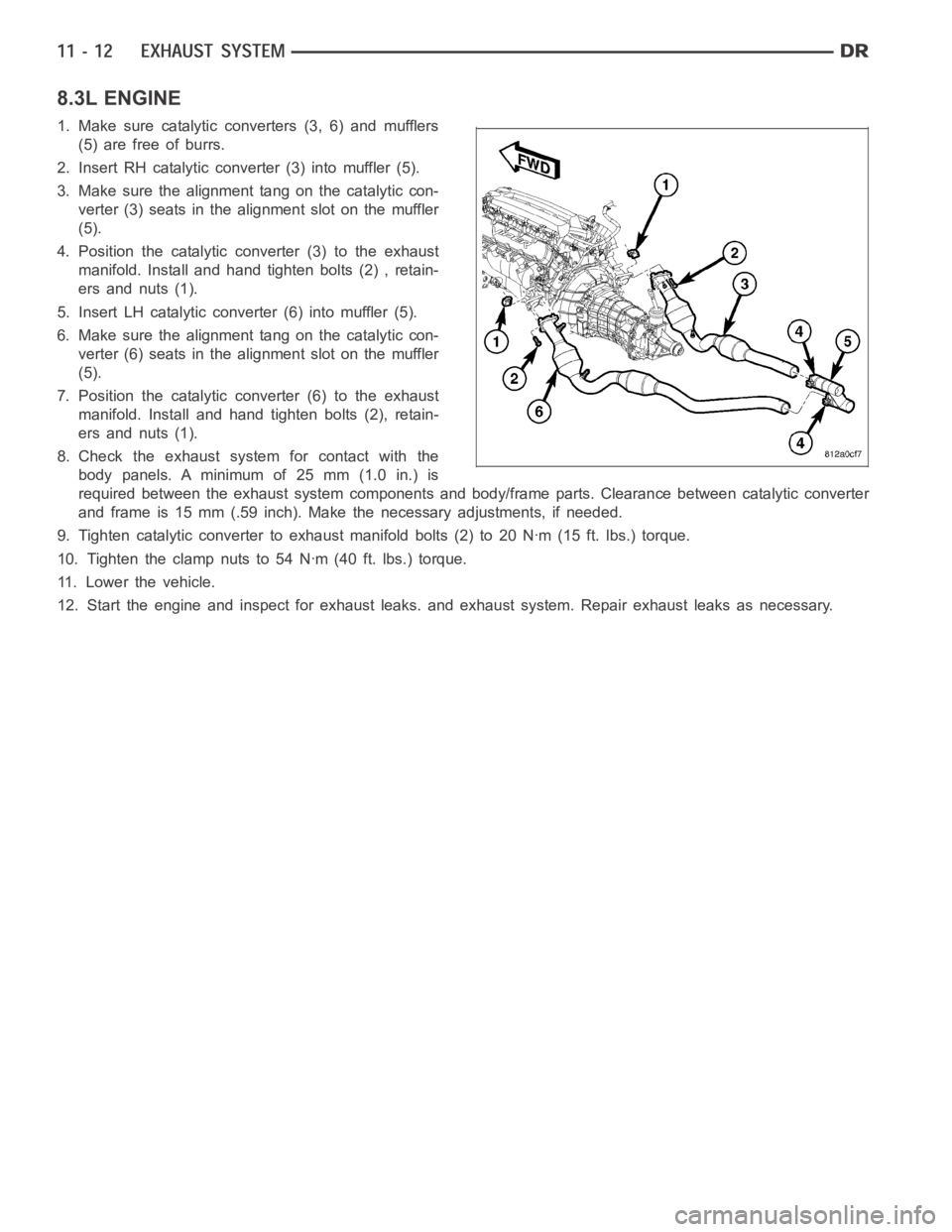
8.3L ENGINE
1. Make sure catalytic converters (3, 6) and mufflers
(5) are free of burrs.
2. Insert RH catalytic converter (3) into muffler (5).
3. Make sure the alignment tang on the catalytic con-
verter (3) seats in the alignment slot on the muffler
(5).
4. Position the catalytic converter (3) to the exhaust
manifold. Install and hand tighten bolts (2) , retain-
ers and nuts (1).
5. Insert LH catalytic converter (6) into muffler (5).
6. Make sure the alignment tang on the catalytic con-
verter (6) seats in the alignment slot on the muffler
(5).
7. Position the catalytic converter (6) to the exhaust
manifold. Install and hand tighten bolts (2), retain-
ers and nuts (1).
8. Check the exhaust system for contact with the
body panels. A minimum of 25 mm (1.0 in.) is
required between the exhaust system components and body/frame parts. Clearance between catalytic converter
and frame is 15 mm (.59 inch). Make the necessary adjustments, if needed.
9. Tighten catalytic converter to exhaust manifold bolts (2) to 20 Nꞏm (15 ft. lbs.) torque.
10. Tighten the clamp nuts to 54 Nꞏm (40 ft. lbs.) torque.
11. Lower the vehicle.
12. Start the engine and inspect for exhaust leaks. and exhaust system. Repair exhaust leaks as necessary.
Page 4535 of 5267
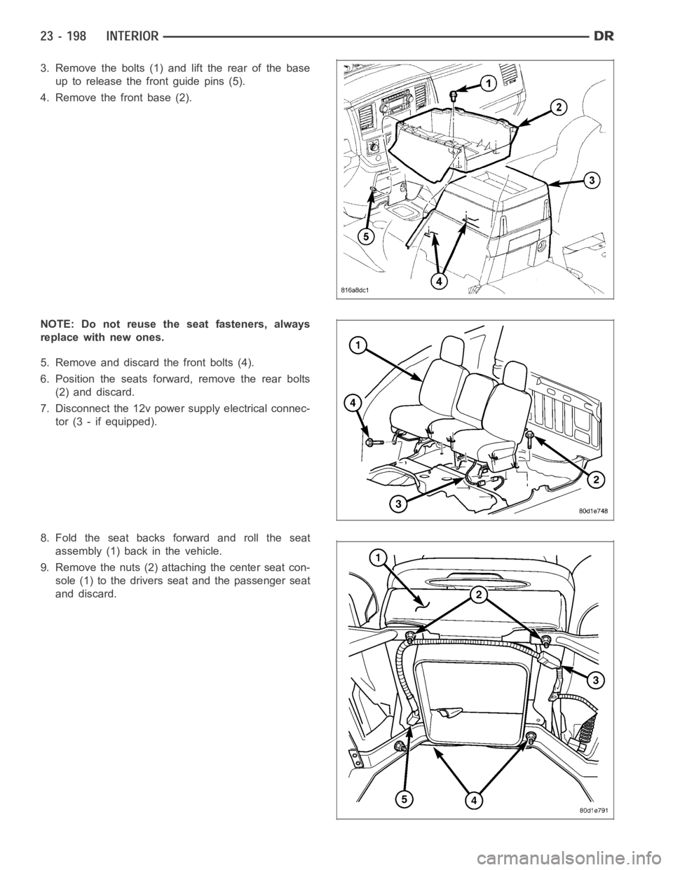
3. Remove the bolts (1) and lift the rear of the base
up to release the front guide pins (5).
4. Remove the front base (2).
NOTE: Do not reuse the seat fasteners, always
replace with new ones.
5. Remove and discard the front bolts (4).
6. Position the seats forward, remove the rear bolts
(2) and discard.
7. Disconnect the 12v power supply electrical connec-
tor (3 - if equipped).
8. Fold the seat backs forward and roll the seat
assembly (1) back in the vehicle.
9. Remove the nuts (2) attaching the center seat con-
sole (1) to the drivers seat and the passenger seat
and discard.
Page 4538 of 5267
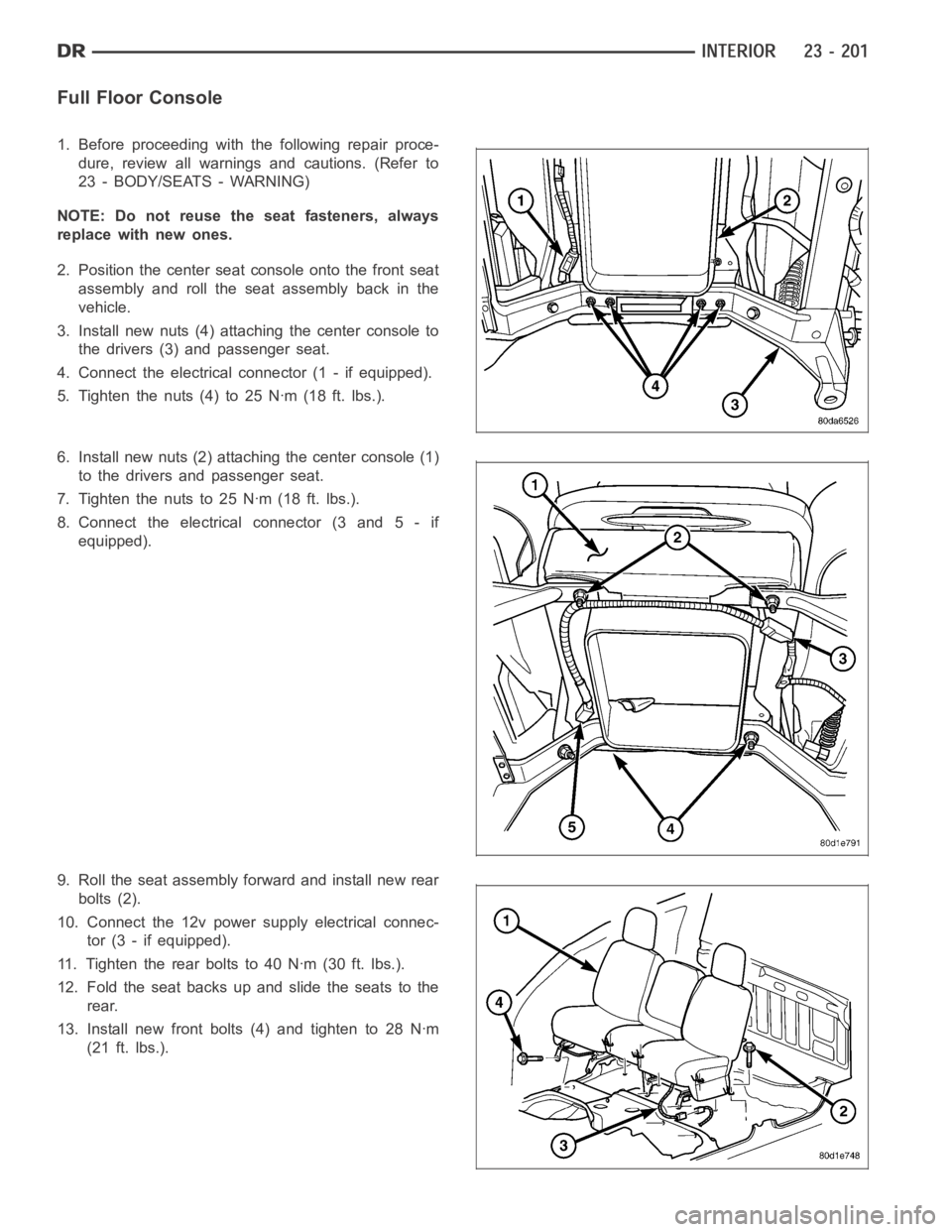
Full Floor Console
1. Before proceeding with the following repair proce-
dure, review all warnings and cautions. (Refer to
23 - BODY/SEATS - WARNING)
NOTE: Do not reuse the seat fasteners, always
replace with new ones.
2. Position the center seat console onto the front seat
assembly and roll the seat assembly back in the
vehicle.
3. Install new nuts (4) attaching the center console to
the drivers (3) and passenger seat.
4. Connect the electrical connector (1 - if equipped).
5. Tighten the nuts (4) to 25 Nꞏm (18 ft. lbs.).
6. Install new nuts (2) attaching the center console (1)
to the drivers and passenger seat.
7. Tightenthenutsto25Nꞏm(18ft.lbs.).
8. Connect the electrical connector (3 and 5 - if
equipped).
9. Roll the seat assembly forward and install new rear
bolts (2).
10. Connect the 12v power supply electrical connec-
tor (3 - if equipped).
11. Tighten the rear bolts to 40 Nꞏm (30 ft. lbs.).
12. Fold the seat backs up and slide the seats to the
rear.
13. Install new front bolts (4) and tighten to 28 Nꞏm
(21 ft. lbs.).
Page 4560 of 5267
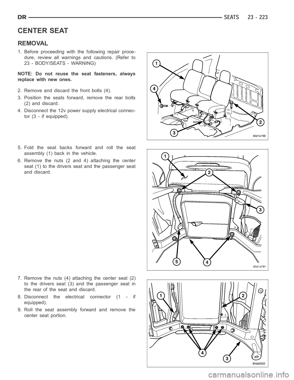
CENTER SEAT
REMOVAL
1. Before proceeding with the following repair proce-
dure, review all warnings and cautions. (Refer to
23 - BODY/SEATS - WARNING)
NOTE: Do not reuse the seat fasteners, always
replace with new ones.
2. Remove and discard the front bolts (4).
3. Position the seats forward, remove the rear bolts
(2) and discard.
4. Disconnect the 12v power supply electrical connec-
tor (3 - if equipped).
5. Fold the seat backs forward and roll the seat
assembly (1) back in the vehicle.
6. Remove the nuts (2 and 4) attaching the center
seat (1) to the drivers seat and the passenger seat
and discard.
7. Remove the nuts (4) attaching the center seat (2)
to the drivers seat (3) and the passenger seat in
the rear of the seat and discard.
8. Disconnect the electrical connector (1 - if
equipped).
9. Roll the seat assembly forward and remove the
center seat portion.