2006 DODGE RAM SRT-10 rear view mirror
[x] Cancel search: rear view mirrorPage 4352 of 5267
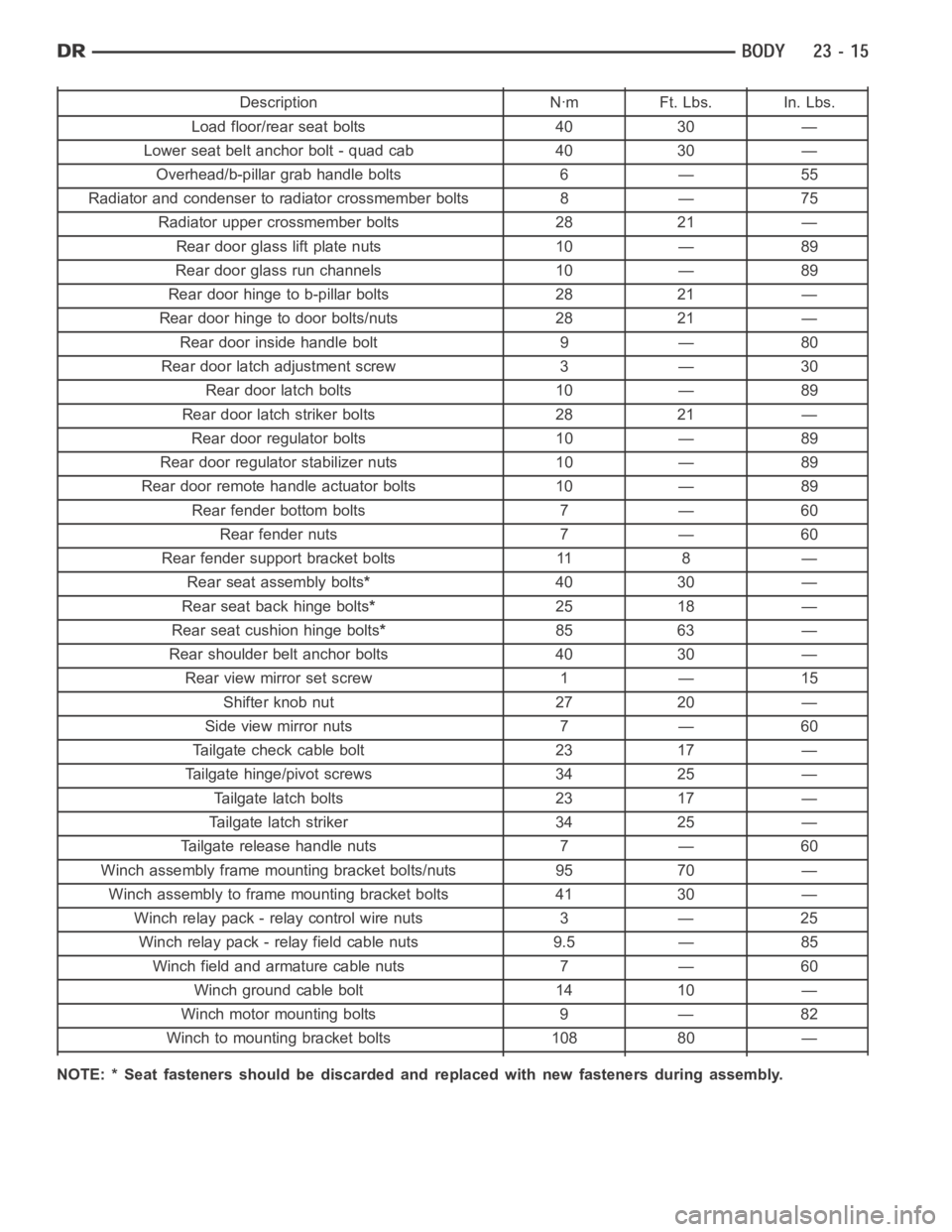
Description Nꞏm Ft. Lbs. In. Lbs.
Load floor/rear seat bolts 40 30 —
Lower seat belt anchor bolt - quad cab 40 30 —
Overhead/b-pillar grab handle bolts 6 — 55
Radiator and condenser to radiator crossmember bolts 8 — 75
Radiator upper crossmember bolts 28 21 —
Rear door glass lift plate nuts 10 — 89
Rear door glass run channels 10 — 89
Rear door hinge to b-pillar bolts 28 21 —
Rear door hinge to door bolts/nuts 28 21 —
Rear door inside handle bolt 9 — 80
Rear door latch adjustment screw 3 — 30
Rear door latch bolts 10 — 89
Rear door latch striker bolts 28 21 —
Rear door regulator bolts 10 — 89
Rear door regulatorstabilizer nuts 10 — 89
Rear door remote handle actuator bolts 10 — 89
Rear fender bottom bolts 7 — 60
Rear fender nuts 7 — 60
Rear fender support bracket bolts 11 8 —
Rear seat assembly bolts*40 30 —
Rear seat back hinge bolts*25 18 —
Rear seat cushion hinge bolts*85 63 —
Rear shoulder belt anchor bolts 40 30 —
Rear view mirror set screw 1 — 15
Shifter knob nut 27 20 —
Side view mirror nuts 7 — 60
Tailgate check cable bolt 23 17 —
Tailgate hinge/pivot screws 34 25 —
Tailgate latch bolts 23 17 —
Tailgate latch striker 34 25 —
Tailgate release handle nuts 7 — 60
Winch assembly frame mounting bracket bolts/nuts 95 70 —
Winch assembly to frame mounting bracket bolts 41 30 —
Winch relay pack - relay control wire nuts 3 — 25
Winch relay pack - relay field cable nuts 9.5 — 85
Winch field and armature cable nuts 7 — 60
Winch ground cable bolt 14 10 —
Winch motor mounting bolts 9 — 82
Winch to mounting bracket bolts 108 80 —
NOTE: * Seat fasteners should be discarded and replaced with new fastenersduring assembly.
Page 4365 of 5267
page page
DOOR
REMOVAL .................................... 29
INSTALLATION ............................... 29
ADJUSTMENTS ............................... 29
DOOR GLASS
REMOVAL .................................... 34
INSTALLATION ............................... 35
EXTERIOR HANDLE
REMOVAL .................................... 36
INSTALLATION ............................... 36
GLASS RUN CHANNEL
REMOVAL
FRONT-ALL MODELS ....................... 37
REAR-QUAD CAB ........................... 37
REAR-STANDARD CAB ..................... 38
INSTALLATION
FRONT-ALL MODELS ....................... 38
REAR-QUAD CAB ........................... 39
REAR-STANDARD CAB ..................... 39
HINGE
REMOVAL .................................... 40
INSTALLATION ............................... 40
INTERIOR HANDLE ACTUATOR
REMOVAL .................................... 41
INSTALLATION ............................... 41
LATCH
REMOVAL .................................... 42INSTALLATION ............................... 43
ADJUSTMENTS ............................... 44
LATCH STRIKER
REMOVAL .................................... 45
INSTALLATION ............................... 45
ADJUSTMENTS ............................... 46
LOCK CYLINDER
REMOVAL .................................... 47
INSTALLATION ............................... 47
TRIM PANEL
REMOVAL .................................... 48
INSTALLATION ............................... 49
WATERDAM
REMOVAL .................................... 50
INSTALLATION ............................... 50
WINDOW REGULATOR - POWER
REMOVAL .................................... 51
INSTALLATION ............................... 52
WINDOW REGULATOR - MANUAL
REMOVAL .................................... 53
INSTALLATION ............................... 54
SIDE VIEW MIRROR FLAG
REMOVAL .................................... 55
INSTALLATION ............................... 55
Page 4423 of 5267
page page
BODY ISOLATORS
REMOVAL .................................... 87
INSTALLATION ............................... 87
BODY SIDE MOLDINGS
REMOVAL .................................... 88
INSTALLATION ............................... 88
CARGO BOX
REMOVAL .................................... 89
INSTALLATION ............................... 89
CARGO BOX - TIE DOWN
REMOVAL .................................... 91
INSTALLATION ............................... 91
COWL GRILLE
REMOVAL .................................... 92
INSTALLATION ............................... 92
EXTERIOR NAME PLATES
REMOVAL .................................... 93
INSTALLATION ............................... 94
FRONT FENDER
REMOVAL .................................... 95
INSTALLATION ............................... 95
FUEL FILL DOOR
REMOVAL .................................... 96
INSTALLATION ............................... 96
GRILLE
REMOVAL .................................... 97
INSTALLATION ............................... 97
GRILLE FRAME
REMOVAL .................................... 98
INSTALLATION ............................... 98
REAR FENDER-QUAD CAB MODELS
REMOVAL .................................... 99
INSTALLATION .............................. 100
SIDE VIEW MIRROR
REMOVAL ................................... 103
INSTALLATION .............................. 103
SIDE VIEW MIRROR GLASS
REMOVAL ................................... 104INSTALLATION .............................. 105
UPPER RADIATOR CROSSMEMBER
REMOVAL ................................... 107
INSTALLATION .............................. 107
FRONT WHEELHOUSE SPLASH SHIELD
REMOVAL ................................... 109
INSTALLATION .............................. 109
REAR WHEELHOUSE SPLASH SHIELD
REMOVAL ................................... 110
INSTALLATION .............................. 110
BELLY PAN-SRT-10
REMOVAL ................................... 111
INSTALLATION ............................... 111
CLADDING-BODY SIDE - BOX - SRT-10
REMOVAL ................................... 112
INSTALLATION .............................. 113
CLADDING-BODY SIDE - CAB - SRT-10
REMOVAL ................................... 115
INSTALLATION .............................. 115
CLADDING-BODY SIDE - DOOR - SRT-10
REMOVAL ................................... 117
INSTALLATION .............................. 117
CLADDING-BODY SIDE - FENDER SRT-10
REMOVAL ................................... 119
INSTALLATION .............................. 119
SPOILER - SRT-10
REMOVAL
WITHOUT CARGO BOX COVER ............ 120
WITH CARGO BOX COVER ................ 120
INSTALLATION
WITHOUT CARGO BOX COVER ............ 121
WITH CARGO BOX COVER ................ 121
FLARE MOLDING-FRONT WHEEL OPENING
REMOVAL ................................... 122
INSTALLATION .............................. 123
FLARE MOLDING-REAR WHEEL OPENING
REMOVAL ................................... 124
INSTALLATION .............................. 125
Page 4513 of 5267
page page
INTERIOR
CAUTION ................................... 177
4WD FLOOR SHIFT BOOT
REMOVAL ................................... 178
INSTALLATION .............................. 178
A-PILLAR TRIM/GRAB HANDLE
REMOVAL ................................... 180
INSTALLATION .............................. 180
B-PILLAR GRAB HANDLE
REMOVAL ................................... 181
INSTALLATION .............................. 181
B-PILLAR LOWER TRIM
REMOVAL ................................... 182
INSTALLATION .............................. 183
B-PILLAR UPPER TRIM
REMOVAL ................................... 184
INSTALLATION .............................. 185
C-PILLAR LOWER TRIM
REMOVAL ................................... 187
INSTALLATION .............................. 187
C-PILLAR UPPER TRIM
REMOVAL ................................... 188
INSTALLATION .............................. 188
CARPETS AND FLOOR MATS
REMOVAL ................................... 189
INSTALLATION .............................. 191
COAT HOOK
REMOVAL ................................... 194
INSTALLATION .............................. 194
COWL TRIM
REMOVAL ................................... 195INSTALLATION .............................. 195
FLOOR CONSOLE
REMOVAL ................................... 196
INSTALLATION .............................. 199
HEADLINER
REMOVAL ................................... 202
INSTALLATION .............................. 202
LOAD FLOOR
REMOVAL ................................... 204
INSTALLATION .............................. 205
REAR CAB BACK PANEL TRIM
REMOVAL ................................... 206
INSTALLATION .............................. 207
REAR DOOR SILL TRIM COVER
REMOVAL ................................... 209
INSTALLATION .............................. 209
REAR VIEW MIRROR
REMOVAL ................................... 210
INSTALLATION
INSTALLATION ............................ 210
REAR VIEW MIRROR MOUNTING BRACKET . 210
SUN VISOR
REMOVAL ................................... 212
INSTALLATION .............................. 212
SUN VISOR SUPPORT
REMOVAL ................................... 213
INSTALLATION .............................. 213
BODY VENT
REMOVAL ................................... 214
INSTALLATION .............................. 214
Page 4539 of 5267
HEADLINER
REMOVAL
NOTE: Headliner for Quad Cab model shown. Reg-
ular cab similar.
1. Remove the A-pillar trim panels (Refer to 23 -
BODY/INTERIOR/A-PILLAR TRIM - REMOVAL).
2. Remove the upper B-pillar trim panels (Refer to 23
- BODY/INTERIOR/B-PILLAR UPPER TRIM -
REMOVAL).
3. On Quad Cab models, remove the upper C-pillar
trim panels (Refer to 23 - BODY/INTERIOR/C-PIL-
LAR TRIM - REMOVAL).
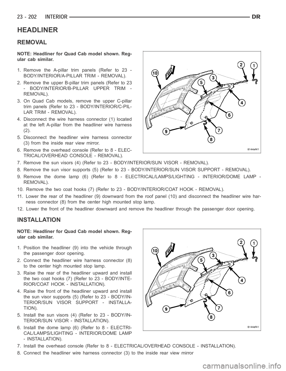
4. Disconnect the wire harness connector (1) located
at the left A-pillar from the headliner wire harness
(2).
5. Disconnect the headliner wire harness connector
(3) from the inside rear view mirror.
6. Remove the overhead console (Refer to 8 - ELEC-
TRICAL/OVERHEAD CONSOLE - REMOVAL).
7. Remove the sun visors (4) (Refer to 23 - BODY/INTERIOR/SUN VISOR - REMOVAL).
8. Remove the sun visor supports (5) (Refer to 23 - BODY/INTERIOR/SUN VISORSUPPORT - REMOVAL).
9. Remove the dome lamp (6) (Refer to 8 -ELECTRICAL/LAMPS/LIGHTING - INTERIOR/DOME LAMP -
REMOVAL).
10. Remove the two coat hooks (7) (Refer to 23 - BODY/INTERIOR/COAT HOOK - REMOVAL).
11. Lower the rear of the headliner (9) downward from the roof panel (10) anddisconnect the headliner wire har-
ness connector (8) from the center high mounted stop lamp.
12. Lower the front of the headliner downward and remove the headliner through the passenger door opening.
INSTALLATION
NOTE: Headliner for Quad Cab model shown. Reg-
ular cab similar.
1. Position the headliner (9) into the vehicle through
the passenger door opening.
2. Connect the headliner wire harness connector (8)
to the center high mounted stop lamp.
3. Raise the rear of the headliner upward and install
the two coat hooks (7) (Refer to 23 - BODY/INTE-
RIOR/COAT HOOK - INSTALLATION).
4. Raise the front of the headliner upward and install
the sun visor supports (5) (Refer to 23 - BODY/IN-
TERIOR/SUN VISOR SUPPORT - INSTALLA-
TION).
5. Install the sun visors (4) (Refer to 23 - BODY/IN-
TERIOR/SUN VISOR - INSTALLATION).
6. Install the dome lamp (6) (Refer to 8 - ELECTRI-
CAL/LAMPS/LIGHTING - INTERIOR/DOME LAMP
- INSTALLATION).
7. Install the overhead console (Refer to 8 - ELECTRICAL/OVERHEAD CONSOLE-INSTALLATION).
8. Connect the headliner wire harness connector (3) to the inside rear viewmirror
Page 4547 of 5267
REAR VIEW MIRROR
REMOVAL
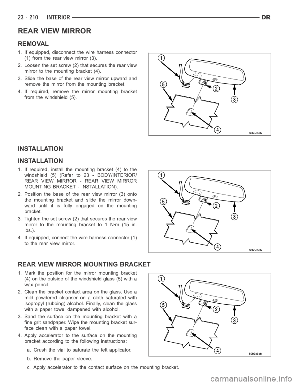
1. If equipped, disconnect the wire harness connector
(1) from the rear view mirror (3).
2. Loosen the set screw (2) that secures the rear view
mirror to the mounting bracket (4).
3. Slide the base of the rear view mirror upward and
remove the mirror from the mounting bracket.
4. If required, remove the mirror mounting bracket
from the windshield (5).
INSTALLATION
INSTALLATION
1. If required, install the mounting bracket (4) to the
windshield (5) (Refer to 23 - BODY/INTERIOR/
REAR VIEW MIRROR - REAR VIEW MIRROR
MOUNTING BRACKET - INSTALLATION).
2. Position the base of the rear view mirror (3) onto
the mounting bracket and slide the mirror down-
ward until it is fully engaged on the mounting
bracket.
3. Tighten the set screw (2) that secures the rear view
mirrortothemountingbracketto1Nꞏm(15in.
lbs.).
4. If equipped, connect the wire harness connector (1)
to the rear view mirror.
REAR VIEW MIRROR MOUNTING BRACKET
1.Markthepositionforthemirrormountingbracket
(4) on the outside of the windshield glass (5) with a
wax pencil.
2. Clean the bracket contact area on the glass. Use a
mild powdered cleanser on a cloth saturated with
isopropyl (rubbing) alcohol. Finally, clean the glass
with a paper towel dampened with alcohol.
3. Sand the surface on the mounting bracket with a
fine grit sandpaper. Wipe the mounting bracket sur-
face clean with a paper towel.
4. Apply accelerator to the surface on the mounting
bracket according to the following instructions:
a. Crush the vial to saturate the felt applicator.
b. Remove the paper sleeve.
c. Apply accelerator to the contact surface on the mounting bracket.
Page 4548 of 5267
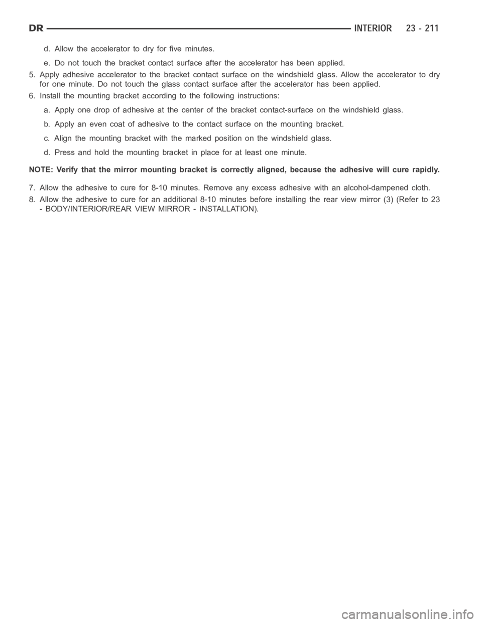
d. Allow the accelerator to dry for five minutes.
e. Do not touch the bracket contact surface after the accelerator has been applied.
5. Apply adhesive accelerator to the bracket contact surface on the windshield glass. Allow the accelerator to dry
for one minute. Do not touch the glass contact surface after the accelerator has been applied.
6. Install the mounting bracket according to the following instructions:
a. Apply one drop of adhesive at the center of the bracket contact-surface on the windshield glass.
b. Apply an even coat of adhesive to the contact surface on the mounting bracket.
c. Align the mounting bracket with the marked position on the windshield glass.
d. Press and hold the mounting bracket in place for at least one minute.
NOTE: Verify that the mirror mounting bracket is correctly aligned, because the adhesive will cure rapidly.
7. Allow the adhesive to cure for 8-10 minutes. Remove any excess adhesive with an alcohol-dampened cloth.
8. Allow the adhesive to cure for an additional 8-10 minutes before installing the rear view mirror (3) (Refer to 23
- BODY/INTERIOR/REAR VIEW MIRROR - INSTALLATION).
Page 4599 of 5267
WINDSHIELD
WARNING
WINDSHIELD SAFETY PRECAUTIONS
Do not operate the vehicle within 24 hours of windshield installation. It takes at least 24 hours for urethane
adhesive to cure. If it is not cured, the windshield may not perform properlyinanaccident.
Urethane adhesives are applied as a system. Use glass cleaner, glass prep solvent, glass primer, PVC
(vinyl) primer and pinch weld (fence) primer provided by the adhesive manufacturer. If not, structural
integrity could be compromised.
DaimlerChrysler does not recommend glass adhesive by brand. Techniciansshould review product
labels and technical data sheets, and use only adhesives that their manufactures warranty and will
restore a vehicle to the requirements of fmvss 212. Technicians should also insure that primers and
cleaners are compatible with the particular adhesive used.
Be sure to refer to the urethane manufacturer’s directions for curing timespecifications and do not
use adhesive after its expiration date.
Vapors that are emitted from the urethane adhesive or primer could cause personal injury or death.
Use them in a well-ventilated area.
Skin contact with urethane adhesive should be avoided. Personal injury ordeath may result.
Always wear eye and hand protection when working with glass.
Protect all painted and trimmed surfaces from coming in contact with urethane or primers.
Be careful not to damage painted surfaces when removing moldings or cutting urethane around windshield.
REMOVAL
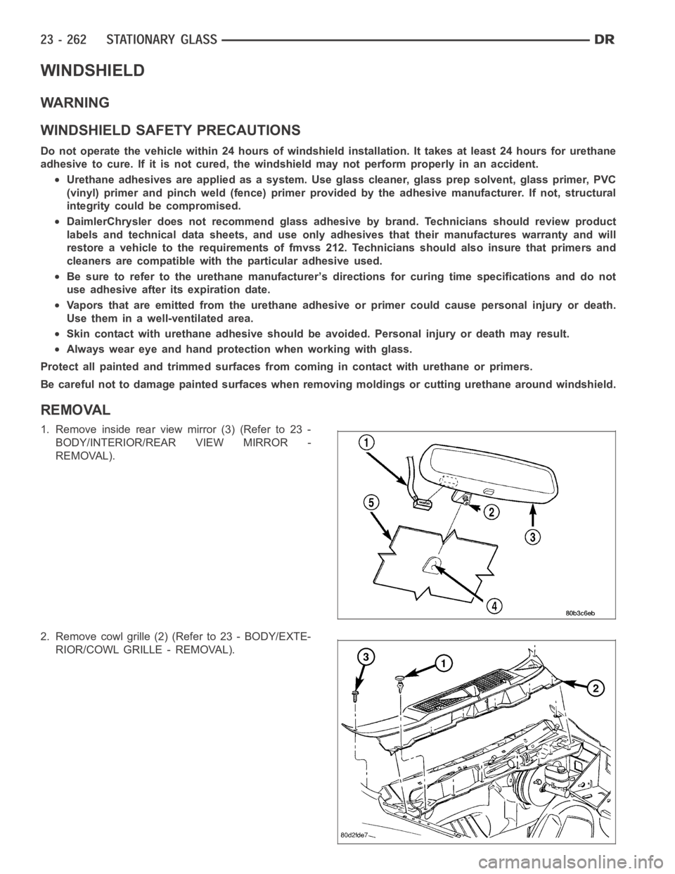
1. Remove inside rear view mirror (3) (Refer to 23 -
BODY/INTERIOR/REAR VIEW MIRROR -
REMOVAL).
2. Remove cowl grille (2) (Refer to 23 - BODY/EXTE-
RIOR/COWL GRILLE - REMOVAL).