2006 DODGE RAM SRT-10 fuel tank capacity
[x] Cancel search: fuel tank capacityPage 1273 of 5267

3.VISUAL AND PHYSICAL INSPECTION
Perform a visual and physical inspection of the entire Evaporative Emission system.
Check for the follow conditions:
- Holes or cracks
- Loose seal points
- Evidence of damaged components
- Incorrect routing of hoses and tubes
- Fuel Cap gasket seal
Were any of the above conditions found?
Ye s>>
Repair as necessary.
Perform the POWERTRAIN VERIFICATION TEST. (Refer to 9 - ENGINE - STANDARD PROCEDURE)
No>>
Go To 4
4.VERIFY EVAPORATIVE EMISSION LEAK
To continue testing you will need Miller Tool #8404A Evaporative EmissionLeak Detector (EELD).
WARNING: Keep lit cigarettes, sparks, flames, and other ignition sourcesaway from the test area to prevent
the ignition of explosive gases. Keep the test area well ventilated.
NOTE: The fuel tank should have between 20% and 80% of fuel tank capacity to properly test the Evap
system.
Connect the red power lead of the EELD to the battery positive terminal and the black ground lead to battery neg-
ative terminal.
Block the vent hose of the canister if using the service port.
Connect shop air to the EELD.
Set the smoke/air control switch to AIR.
Insert the tester’s AIR supply tip (clear hose) into the appropriate calibration orifice on the tester’s control panel
(based on DTC leak size).
Press the remote smoke/air start button.
Position the red flag on the air flow meter so it is aligned with the indicatorball.
When the calibration is complete, release the remote button. The EELD flowmeter is now calibrated in liters per
minute to the size leak indicated by the DTC set in the PCM.
Install the service port adapter #8404-14 on the vehicle’s service port and block the vent hose of the EVAP Canister
(if equipped) or install the #8404-ADP service adaptor into the filter line.
Connect the Air supply hose from the EELD to the service port (if equipped) or to the #8404-ADP adapter.
Press the remote button to activate AIR flow.
NOTE: Larger volume fuel tanks, lower fuel levels or if the vehicle is equipped with a Flow Management
Valve may indicate high flow and will require 4 to 5 minutes to fill.
Compare the flow meter indicator ball reading to the red flag.
ABOVE the red flag indicates a leak present.
BELOW the red flag indicates a sealed system.
Is the indicator ball above the red flag?
Ye s>>
Go To 5
No>>
Refer to the Freeze Frame data recorded in Step 1. If the data indicates thatthe vehicle was in motion
when the DTC was set, verify that all hoses are properly connected. Test Complete.
Page 1283 of 5267

3.VISUAL AND PHYSICAL INSPECTION
Perform a visual and physical inspection of the entire Evaporative Emission system.
Check for the follow conditions:
- Holes or cracks
- Loose seal points
- Evidence of damaged components
- Incorrect routing of hoses and tubes
- Fuel Cap gasket seal
Were any of the above conditions found?
Ye s>>
Repair as necessary.
Perform the POWERTRAIN VERIFICATION TEST. (Refer to 9 - ENGINE - STANDARD PROCEDURE)
No>>
Go To 4
4.VERIFY EVAPORATIVE EMISSION LEAK
To continue testing you will need Miller Tool #8404A Evaporative EmissionLeak Detector (EELD).
WARNING: Keep lit cigarettes, sparks, flames, and other ignition sourcesaway from the test area to prevent
the ignition of explosive gases. Keep the test area well ventilated.
NOTE: The fuel tank should have between 20% and 80% of fuel tank capacity to properly test the Evap
system.
Connect the red power lead of the EELD to the battery positive terminal and the black ground lead to battery neg-
ative terminal.
Block the vent hose of the canister if using the service port.
Connect shop air to the EELD.
Set the smoke/air control switch to AIR.
Insert the tester’s AIR supply tip (clear hose) into the appropriate calibration orifice on the tester’s control panel
(based on DTC leak size).
Press the remote smoke/air start button.
Position the red flag on the air flow meter so it is aligned with the indicatorball.
When the calibration is complete, release the remote button. The EELD flowmeter is now calibrated in liters per
minute to the size leak indicated by the DTC set in the PCM.
Install the service port adapter #8404-14 on the vehicle’s service port and block the vent hose of the EVAP Canister
(if equipped) or install the #8404-ADP service adaptor into the filter line.
Connect the Air supply hose from the EELD to the service port (if equipped) or to the #8404-ADP adapter.
Press the remote button to activate AIR flow.
NOTE: Larger volume fuel tanks, lower fuel levels or if the vehicle is equipped with a Flow Management
Valve may indicate high flow and will require 4 to 5 minutes to fill.
Compare the flow meter indicator ball reading to the red flag.
ABOVE the red flag indicates a leak present.
BELOW the red flag indicates a sealed system.
Is the indicator ball above the red flag?
Ye s>>
Go To 5
No>>
Refer to the INTERMITTENT CONDITION Diagnostic Procedure.
Perform the POWERTRAIN VERIFICATION TEST. (Refer to 9 - ENGINE - STANDARD PROCEDURE)
Page 1287 of 5267

P0460-FUEL LEVEL SENDING UNIT NO CHANGE OVER MILES
For a complete wiring diagramRefer to Section 8W.
When Monitored:
Engine running and fuel level either below 15% or above 85% of capacity.
Set Condition:
The PCM sees low fuel, less than 15%, for more than 120 miles or fuel level does not change by at least 4%
for more than 250 miles.
Possible Causes
PHYSICALLY DAMAGED/DEFORMED/OBSTRUCTED FUEL TANK
FUEL LEVEL SENSOR
Always perform the Pre-Diagnostic Troubleshooting procedure before proceeding. (Refer to 9 - ENGINE -
DIAGNOSIS AND TESTING)
1.CHECKING FOR A DAMAGED/DEFORMED/OBSTRUCTED FUEL TANK
Turn the ignition off.
WARNING: WARNING: The fuel system is under a constant pressure, even with the engine off. Before test-
ing or servicing any fuel system hose, fitting or line, the fuel system pressure must be released.
Inspect the outside of the fuel tank for defects.
Remove the fuel tank.
Remove the fuel pump module from the fuel tank.
Inspect the inside of the fuel tank for any obstructions or deformities.
Is the fuel tank free from defects?
Ye s>>
Go To 2
No>>
Repair or replace the fuel tank as necessary.
Perform POWERTRAIN VERIFICATION TEST. (Refer to 9 - ENGINE - STANDARD PROCEDURE)
2.FUEL LEVEL SENSOR
If there are no possible causes remaining, view repair.
Repair
Replace the Fuel Level Sensor.
Perform POWERTRAIN VERIFICATION TEST. (Refer to 9 - ENGINE - STANDARD PROCEDURE)
Page 2247 of 5267

SENSOR - FUEL LEVEL SENDING UNIT
DESCRIPTION
The fuel gauge sending unit (fuel level sensor) is attached to the side of the fuel pump module. The sending unit
consists of a float, an arm, and a variable resistor track (card).
OPERATION
The fuel pump module has 4 different circuits (wires). Two of these circuits are used for the fuel gauge sending unit
for fuel gauge operation, and for certain OBD II emission requirements. The other 2 wires are used for electric fuel
pump operation.
For Fuel Gauge Operation:A constant current source is supplied to the resistor track on the fuel gauge sending
unit. This is fed directly from the Powertrain Control Module (PCM).NOTE: For diagnostic purposes, this 12V
power source can only be verified with the circuit opened (fuel pump moduleelectrical connector
unplugged). With the connectors plugged, output voltages will vary from about 0.6 volts at FULL, to about
8.6 volts at EMPTY (about 8.6 volts at EMPTY for Jeep models, and about 7.0 volts at EMPTY for Dodge
Truck models).The resistor track is used to vary the voltage (resistance) depending on fuel tank float level. As fuel
level increases, the float and arm move up, which decreases voltage. As fuel level decreases, the float and arm
move down, which increases voltage. The varied voltage signal is returnedback to the PCM through the sensor
return circuit.
Both of the electrical circuits between the fuel gauge sending unit and thePCM are hard-wired (not multi-plexed).
After the voltage signal is sent from the resistor track, and back to the PCM, the PCM will interpret the resistance
(voltage) data and send a message across the multi-plex bus circuits to theinstrument panel cluster. Here it is
translated into the appropriate fuel gauge level reading. Refer to Instrument Panel for additional information.
For OBD II Emission Monitor Requirements:The PCM will monitor the voltage output sent from the resistor track
on the sending unit to indicate fuel level. The purpose of this feature is toprevent the OBD II system from recording/
setting false misfire and fuel systemmonitor diagnostic trouble codes. The feature is activated if the fuel level in the
tank is less than approximately 15 percent of its rated capacity. If equipped with a Leak Detection Pump (EVAP
system monitor), this feature will also be activated if the fuel level in the tank is more than approximately 85 percent
of its rated capacity.
REMOVAL
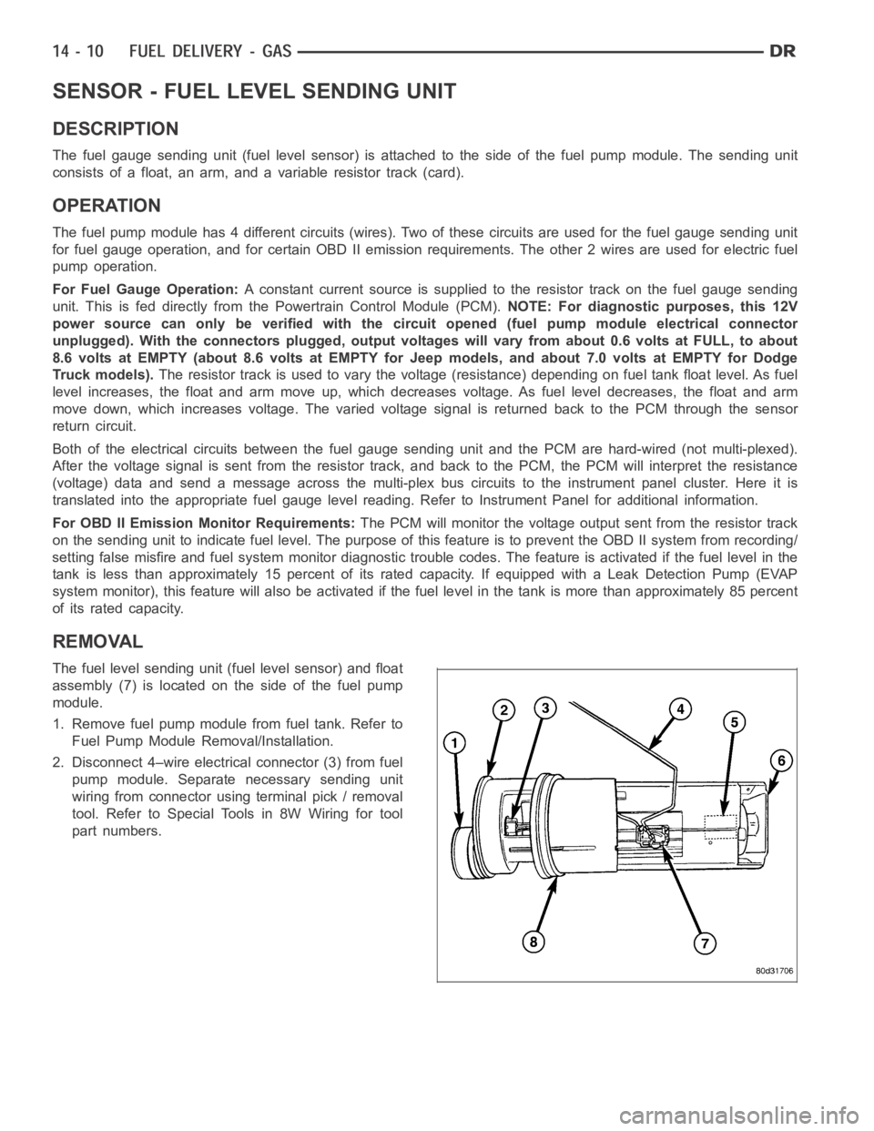
The fuel level sending unit (fuel level sensor) and float
assembly (7) is located on the side of the fuel pump
module.
1. Remove fuel pump module from fuel tank. Refer to
Fuel Pump Module Removal/Installation.
2. Disconnect 4–wire electrical connector (3) from fuel
pump module. Separate necessary sending unit
wiring from connector using terminal pick / removal
tool. Refer to Special Tools in 8W Wiring for tool
part numbers.