Page 2409 of 5267

INSUFFICIENT ASST. OR POOR RETURN TO CENTER
CONDITION POSSIBLE CAUSE CORRECTION
HARD TURNING OR MOMENTARY
INCREASE IN TURNING EFFORT1. Tire pressure. 1. Adjust tire pressure.
2. Low fluid level. 2. Fill to proper level.
3. Loose belt. 3. Adjust or replace.
4. Low pump pressure. 4. Pressure test and repair as
necessary.
5. Internal gear leak. 5. Replace gear.
STEERING WHEEL DOES NOT
WANT TO RETURN TO CENTER
POSITION1. Tire pressure. 1. Adjust tire pressure.
2. Wheel alignment. 2. Align front end.
3. Lack of lubrication. 3. Inspect and lubricate suspension
components.
4. High friction in steering gear. 4. Replace gear.
LOOSE STEERING AND VEHICLE LEAD
CONDITION POSSIBLE CAUSE CORRECTION
EXCESSIVE PLAY IN STEERING
WHEEL1. Worn or loose suspension or
steering components.1. Inspect and repair as necessary.
2. Worn or loose wheel bearings. 2. Inspect and repair or adjust
bearings.
3. Steering gear mounting. 3. Tighten gear mounting bolts to
specification.
4. Gear out of adjustment. 4. Replace gear.
5. Worn or loose steering coupler. 5. Inspect and replace as
necessary.
VEHICLE PULLS OR LEADS TO
ONE SIDE.1. Tire Pressure. 1. Adjust tire pressure.
2. Radial tire lead. 2. Rotate tires.
3. Brakes dragging. 3. Repair as necessary.
4. Wheel alignment. 4. Align front end.
5. Steering gear valve bias. 5. Replace steering gear.
POWER STEERING FLOW AND PRESSURE
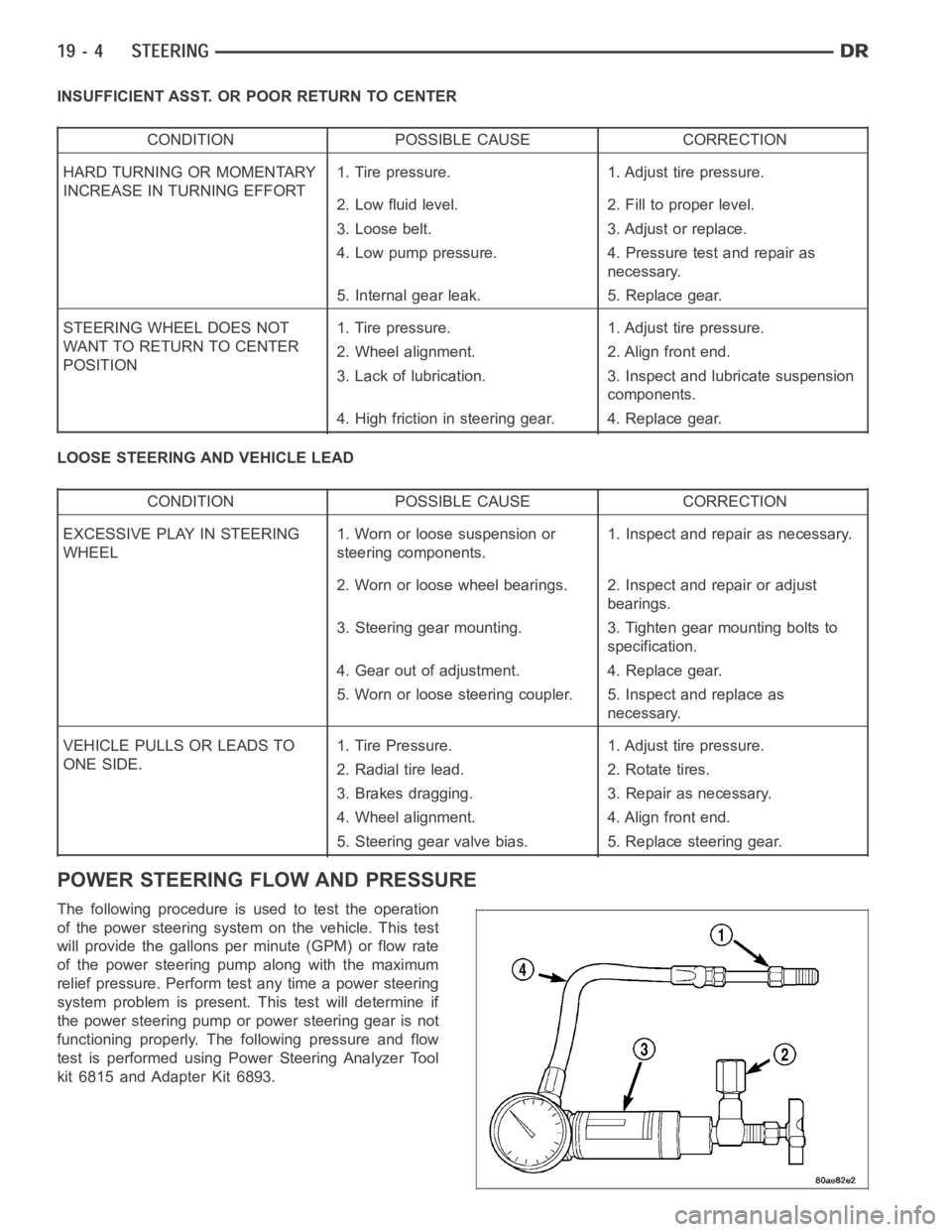
The following procedure is used to test the operation
of the power steering system on the vehicle. This test
will provide the gallons per minute (GPM) or flow rate
of the power steering pump along with the maximum
relief pressure. Perform test any time a power steering
system problem is present. This test will determine if
the power steering pump or power steering gear is not
functioning properly. The following pressure and flow
test is performed using Power Steering Analyzer Tool
kit 6815 and Adapter Kit 6893.
Page 2463 of 5267

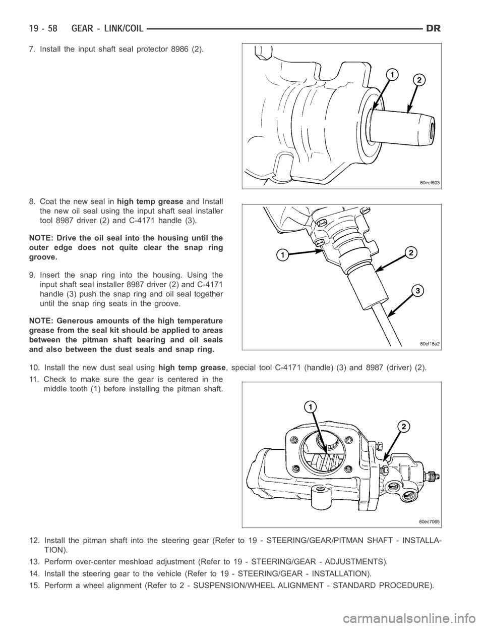
7. Install the input shaft seal protector 8986 (2).
8. Coat the new seal inhigh temp greaseand Install
the new oil seal using the input shaft seal installer
tool 8987 driver (2) and C-4171 handle (3).
NOTE: Drive the oil seal into the housing until the
outer edge does not quite clear the snap ring
groove.
9. Insert the snap ring into the housing. Using the
input shaft seal installer 8987 driver (2) and C-4171
handle (3) push the snap ring and oil seal together
until the snap ring seats in the groove.
NOTE: Generous amounts of the high temperature
grease from the seal kit should be applied to areas
between the pitman shaft bearing and oil seals
and also between the dust seals and snap ring.
10. Install the new dust seal usinghigh temp grease, special tool C-4171 (handle) (3) and 8987 (driver) (2).
11. Check to make sure the gear is centered in the
middle tooth (1) before installing the pitman shaft.
12. Install the pitman shaft into the steering gear (Refer to 19 - STEERING/GEAR/PITMAN SHAFT - INSTALLA-
TION).
13. Perform over-center meshload adjustment (Refer to 19 - STEERING/GEAR- ADJUSTMENTS).
14. Install the steering gear to the vehicle (Refer to 19 - STEERING/GEAR - INSTALLATION).
15. Perform a wheel alignment (Refer to2 - SUSPENSION/WHEEL ALIGNMENT - STANDARD PROCEDURE).
Page 2465 of 5267
7. Remove the pitman shaft cover (3) bolts.
NOTE: The pitman shaft will not clear the housing
if it is not centered.
8. Remove the pitman shaft (1) from the gear.
9. Remove the cover (3) if needed by loosing the
adjuster nut (4). Then removing the cover from the
pitman shaft.
INSTALLATION
GAS
1. Coat the seal withpower steering fluid.
2. Install pitman shaft (1) into the steering gear until it
fully seats into the bearing.
3. Install the new cover bolts and tighten to 68 Nꞏm
(50 ft. lbs.).
4. Perform over-center meshload adjustment, (Refer
to 19 - STEERING/GEAR - ADJUSTMENTS).
5. Install the pitman arm (Refer to 19 - STEERING/LINKAGE/PITMAN ARM - INSTALLATION).
6. Perform a wheel alignment (Refer to 2- SUSPENSION/WHEEL ALIGNMENT - STANDARD PROCEDURE).
Page 2466 of 5267
DIESEL
1. Coat the seal withpower steering fluid.
2. Install the pitman shaft (1) into the steering gear
until it fully seats into the bearing.
3. Install the new cover bolts and tighten to 68 Nꞏm
(50 ft. lbs.).
4. Perform over-center meshload adjustment (Refer to
19 - STEERING/GEAR - ADJUSTMENTS).
5. Install the steering gear (Refer to 19 - STEERING/GEAR - INSTALLATION).
6. Install the pitman arm (Refer to 19 - STEERING/LINKAGE/PITMAN ARM - INSTALLATION).
7. Perform a wheel alignment (Refer to 2- SUSPENSION/WHEEL ALIGNMENT - STANDARD PROCEDURE).
Page 2476 of 5267
DRAG LINK
REMOVAL
1. Remove the drag link nut (2) from the pitman arm
side (1).
2. Remove the drag link nut from the knuckle side.
3. Remove the drag link (2) from the right knuckle
and pitman arm (1) with Puller C-3894A (3).
INSTALLATION
1. Install the drag link (2) to the pitman arm (1). Install
the nut and tighten to 88 Nꞏm (65 ft. lbs.).
2. Install the drag link to the right steering knuckle.
Install the nut and tighten to 54 Nꞏm (40 ft. lbs.).
Then an additional 90°.
3. Install tie rod to the left steering knuckle and drag
link. Install the nuts and tighten to 54 Nꞏm (40 ft.
lbs.). Then an additional 90°.
4. Remove the supports and lower the vehicle to the
surface. Center steering wheel and adjust toe,
(Refer to 2 - SUSPENSION/WHEEL ALIGNMENT -
STANDARD PROCEDURE).
5. After adjustment tighten tie rod adjustment sleeve
clamp bolts to 61 Nꞏm (45 ft. lbs.).
NOTE:Positiontheclamponthesleevesoretain-
ing bolt is located on the bottom side of the sleeve.
Page 2478 of 5267
INSTALLATION
1. Align reference marks and install pitman arm.
2. Install the lock washer and retaining nut on the pit-
man shaft and tighten nut to 251 Nꞏm (185 ft. lbs.).
3. Install the drag link (1) to the pitman arm (5). Install
thenut(4)andtightento54Nꞏm(40ft.lbs.).Then
an additional 90°.
4. Remove the supports and lower the vehicle to the
surface. Center steering wheel and adjust toe,
(Refer to 2 - SUSPENSION/WHEEL ALIGNMENT -
STANDARD PROCEDURE).
5. After adjustment tighten tie rod adjustment sleeve
clamp bolts to 61 Nꞏm (45 ft. lbs.).
NOTE:Positiontheclamponthesleevesoretain-
ing bolt is located on the bottom side of the
sleeve.
Page 2479 of 5267
TIE ROD END
REMOVAL
1. Remove tie rod nuts (1).
2. Remove tie rod from drag link and left knuckle with
remover C-4150A.
INSTALLATION
1. Install tie rod (2) to the left steering knuckle and
drag link. Install the nuts (1) and tighten to 54 Nꞏm
(40 ft. lbs.) Then an additional 90°.
2. Remove the supports and lower the vehicle to the
surface. Center steering wheel and adjust toe,
(Refer to 2 - SUSPENSION/WHEEL ALIGNMENT -
STANDARD PROCEDURE).
3. After adjustment tighten tie rod adjustment sleeve
clamp bolts to 61 Nꞏm (45 ft. lbs.).
NOTE: Position the clamp on the sleeve so retaining bolt is located on the bottom side of the sleeve.