2006 DODGE RAM SRT-10 oil change
[x] Cancel search: oil changePage 39 of 5267

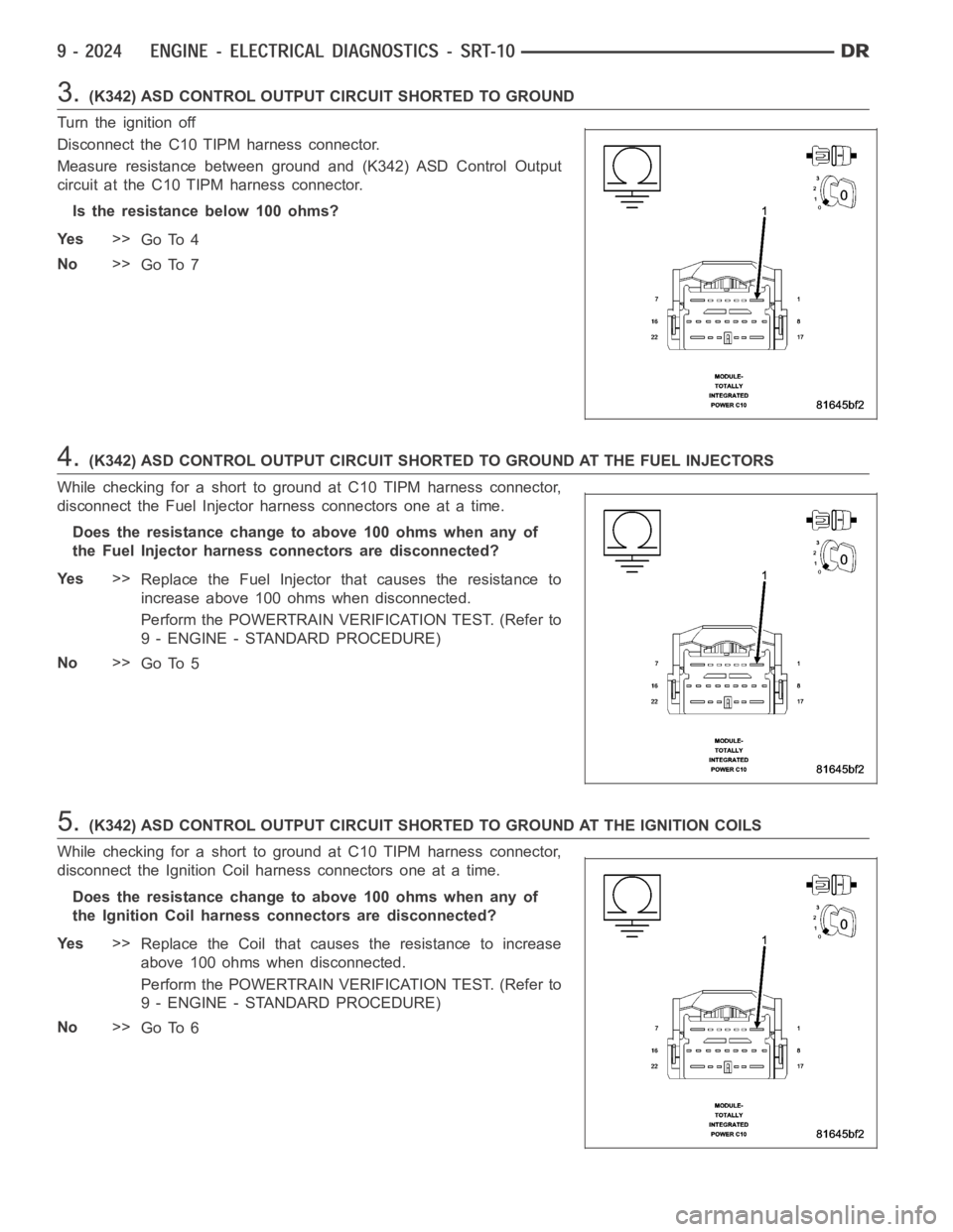
3.(K342) ASD CONTROL OUTPUT CIRCUIT SHORTED TO GROUND
Turn the ignition off
Disconnect the C10 TIPM harness connector.
Measure resistance between ground and (K342) ASD Control Output
circuit at the C10 TIPM harness connector.
Istheresistancebelow100ohms?
Ye s>>
Go To 4
No>>
Go To 7
4.(K342) ASD CONTROL OUTPUT CIRCUIT SHORTED TO GROUND AT THE FUEL INJECTORS
While checking for a short to ground at C10 TIPM harness connector,
disconnect the Fuel Injector harness connectors one at a time.
Does the resistance change to above 100 ohms when any of
the Fuel Injector harness connectors are disconnected?
Ye s>>
Replace the Fuel Injector that causes the resistance to
increase above 100 ohms when disconnected.
Perform the POWERTRAIN VERIFICATION TEST. (Refer to
9 - ENGINE - STANDARD PROCEDURE)
No>>
Go To 5
5.(K342) ASD CONTROL OUTPUT CIRCUIT SHORTED TO GROUND AT THE IGNITION COILS
While checking for a short to ground at C10 TIPM harness connector,
disconnect the Ignition Coil harness connectors one at a time.
Does the resistance change to above 100 ohms when any of
the Ignition Coil harness connectors are disconnected?
Ye s>>
Replace the Coil that causes the resistance to increase
above 100 ohms when disconnected.
Perform the POWERTRAIN VERIFICATION TEST. (Refer to
9 - ENGINE - STANDARD PROCEDURE)
No>>
Go To 6
Page 43 of 5267

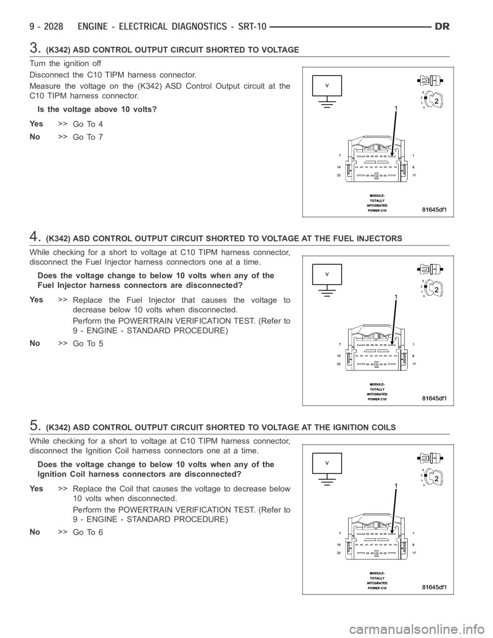
3.(K342) ASD CONTROL OUTPUT CIRCUIT SHORTED TO VOLTAGE
Turn the ignition off
Disconnect the C10 TIPM harness connector.
Measure the voltage on the (K342) ASD Control Output circuit at the
C10 TIPM harness connector.
Is the voltage above 10 volts?
Ye s>>
Go To 4
No>>
Go To 7
4.(K342) ASD CONTROL OUTPUT CIRCUIT SHORTED TO VOLTAGE AT THE FUEL INJECTORS
While checking for a short to voltage at C10 TIPM harness connector,
disconnect the Fuel Injector harness connectors one at a time.
Does the voltage change to below 10 volts when any of the
Fuel Injector harness connectors are disconnected?
Ye s>>
Replace the Fuel Injector that causes the voltage to
decrease below 10 volts when disconnected.
Perform the POWERTRAIN VERIFICATION TEST. (Refer to
9 - ENGINE - STANDARD PROCEDURE)
No>>
Go To 5
5.(K342) ASD CONTROL OUTPUT CIRCUIT SHORTED TO VOLTAGE AT THE IGNITION COILS
While checking for a short to voltage at C10 TIPM harness connector,
disconnect the Ignition Coil harness connectors one at a time.
Does the voltage change to below 10 volts when any of the
Ignition Coil harness connectors are disconnected?
Ye s>>
Replace the Coil that causes the voltage to decrease below
10 volts when disconnected.
Perform the POWERTRAIN VERIFICATION TEST. (Refer to
9 - ENGINE - STANDARD PROCEDURE)
No>>
Go To 6
Page 123 of 5267

P1521–INCORRECT ENGINE OIL TYPE
When Monitored:
Engine Running.
Set Condition:
Using the oil pressure, oil temperature and other vital engine inputs the PCM can determine the engine oil
viscosity. Incorrect viscosity will effect the operation of the MDS by delaying cylinder activation.
Possible Causes
INCORRECT ENGINE OIL TYPE
ENGINE OIL CONTAMINATION
ENGINE OIL
Always perform the Pre-Diagnostic Troubleshooting procedure before proceeding. (Refer to 9 - ENGINE -
DIAGNOSIS AND TESTING).
Diagnostic Test
1.ACTIVE DTC
NOTE: Review the customers oil change history. Make sure the customers is using the correct engine oil
viscosity. If the incorrect oil is being used, change the oil, using the correct engine oil viscosity.
Ignition on, engine off.
With the scan tool, read DTCs.
Is the DTC active at this time?
Ye s>>
Go to 2
No>>
Te s t C o m p l e t e .
2.ENGINE OIL
NOTE: If any engine oil pressure or oil temperature DTCs set along with P1521, repair them before continu-
ing with the P1521 diagnostics.
The following conditions must be checked.
OEM recommended oil viscosity is being used.
Customer is following the oil change schedule.
Check the engine oil for contamination. (i.e., fuel and/or engine coolant)
Internal engine condition that may effect oil pressure.
Were any of the above condition found?
Ye s>>
Repair as necessary.
Perform the POWERTRAIN VERIFICATION TEST. (Refer to 9 - ENGINE - STANDARD PROCEDURE)
No>>
Change the engine oil using the correct oil viscosity.
Perform the POWERTRAIN VERIFICATION TEST. (Refer to 9 - ENGINE - STANDARD PROCEDURE)
Page 912 of 5267

P0355-IGNITION COIL #5 PRIMARY
CIRCUIT................................. 1948
P0420-1/1 CATALYTIC CONVERTER
EFFICIENCY............................. 1952
P0432-2/1 CATALYTIC CONVERTER
EFFICIENCY............................. 1955
P0441-EVAP PURGE FLOW MONITOR . . . . . 1958
P0442-EVAP LEAK MONITOR MEDIUM
(0.040) LEAK DETECTED.................. 1962
P0443-EVAP PURGE SOLENOID CIRCUIT . . 1968
P0455-EVAP LEAK MONITOR LARGE LEAK
DETECTED............................... 1972
P0460-FUEL LEVEL SENDING UNIT NO
CHANGE OVER MILES.................... 1978
P0462-FUEL LEVEL SENDING UNIT VOLTS
TOO LOW................................ 1979
P0463-FUEL LEVEL SENSOR 1 CIRCUIT
HIGH.................................... 1982
P0500-NO VEHICLE SPEED SIGNAL ....... 1986
P0505-IDLE AIR CONTROL MOTOR
CIRCUITS................................ 1989
P0513-INVALID SKREEM KEY ............. 1994
P0522-OIL PRESSURE CIRCUIT LOW ...... 1996
P0523-OIL PRESSURE CIRCUIT HIGH ..... 2000
P0601-PCM INTERNAL CONTROLLER
FAILURE................................. 2003
P0622-GENERATOR FIELD NOT
SWITCHING PROPERLY.................. 2004
P0645-A/C CLUTCH RELAY CIRCUIT . . ..... 2008
P0801-REVERSE GEAR LOCKOUT CIRCUIT
OPEN OR SHORTED...................... 2012
P1195-O2 SENSOR 1/1 SLOW DURING
CATALYST MONITOR..................... 2016
P1196-O2 SENSOR 2/1 SLOW DURING
CATALYST MONITOR..................... 2019
P126B-ASD CONTROL CIRCUIT 2 LOW .... 2022
P126C-ASD CONTROL CIRCUIT 2 HIGH .... 2026
P126D-ASD CONTROL CIRCUIT 2 OPEN . . . 2030
P126E-ASD CONTROL CIRCUIT
OVERCURRENT.......................... 2034
P1272-A/C CLUTCH CONTROL CIRCUIT 2
LOW..................................... 2038
P1273-A/C CLUTCH CONTROL CIRCUIT 2
HIGH.................................... 2041
P1274-A/C CLUTCH CONTROL CIRCUIT 2
OPEN.................................... 2045
P1275-A/C CLUTCH CONTROL CIRCUIT 2
OVERCURRENT.......................... 2049
P1277-STARTER CONTROL CIRCUIT 2 LOW
(TIPM)................................... 2052
P1278-STARTER CONTROL CIRCUIT 2
HIGH (TIPM).............................. 2055
P1279-STARTER CONTROL CIRCUIT 2
OPEN (TIPM)............................. 2058
P127A-STARTER CONTROL CIRCUIT 2
OVERCURRENT.......................... 2061
P127C-FUEL PUMP CONTROL CIRCUIT 2
LOW..................................... 2064P127D-FUEL PUMP CONTROL CIRCUIT 2
HIGH.................................... 2067
P127E-FUEL PUMP CONTROL CIRCUIT 2
OPEN (TIPM)............................. 2071
P0127F-FUEL PUMP CONTROL CIRCUIT 2
OVERCURRENT (TIPM)................... 2075
P1281-ENGINE IS COLD TOO LONG ....... 2078
P1282-FUEL PUMP/SYSTEM RELAY
CONTROL CIRCUIT....................... 2079
P1294-TARGET IDLE NOT REACHED ...... 2082
P1296-NO 5-VOLTS TO MAP SENSOR ..... 2085
P1297-NO CHANGE IN MAP FROM START
TO RUN.................................. 2089
P1388-AUTO SHUTDOWN RELAY CONTROL
CIRCUIT................................. 2094
P1389-NO ASD RELAY OUTPUT VOLTAGE
AT P C M.................................. 2097
P1391-INTERMITTENT LOSS OF CMP OR
CKP
..................................... 2100
P1398-MIS-FIRE ADAPTIVE NUMERATOR
AT L I M I T................................. 2104
P1486-EVAP LEAK MONITOR PINCHED
HOSE FOUND............................ 2106
P1492-AMBIENT/BATTERY TEMPERATURE
SENSOR VOLTAGE TOO HIGH............. 2110
P1493-AMBIENT/BATTERY TEMPERATURE
SENSOR VOLTAGE TOO LOW............. 2114
P1494-LEAK DETECTION PUMP SWITCH
OR MECHANICAL FAULT.................. 2117
P1495-LEAK DETECTION PUMP SOLENOID
CIRCUIT................................. 2121
P1499-HYDRAULIC FAN SOLENOID
CIRCUIT................................. 2126
P1594-CHARGING SYSTEM VOLTAGE TOO
HIGH.................................... 2130
P1598-A/C PRESSURE SENSOR VOLTAGE
TOO HIGH............................... 2133
P1599-A/C PRESSURE SENSOR VOLTAGE
TOO LOW................................ 2137
P1682-CHARGING SYSTEM VOLTAGE TOO
LOW..................................... 2141
P1687-NO CLUSTER BUS MESSAGE ...... 2146
P1695-BUS MESSAGE FROM BODY
CONTROL MODULE...................... 2148
P1696-PCM FAILURE EEPROM WRITE
DENIED.................................. 2151
*BRAKE SWITCH SENSE STATUS DOES
NOT CHANGE ON THE SCAN TOOL....... 2153
*CANNOT SHIFT INTO REVERSE .......... 2157
*CHECKING A/C SYSTEM OPERATION
WITH NO DTCS.......................... 2159
*CHECKING CHARGING SYSTEM
OPERATION WITH NO DTCS.............. 2163
*CHECKING RADIATOR FAN OPERATION . . 2167
*CHECKING THE PCM POWER AND
GROUNDS............................... 2169
B2277–CAN GATEWAY INTERNAL
(GATEWAY).............................. 2172
U0001–CAN C BUS CIRCUIT (GATEWAY) . . . 2172
Page 1333 of 5267

3.(K342) ASD CONTROL OUTPUT CIRCUIT SHORTED TO GROUND
Turn the ignition off
Disconnect the C10 TIPM harness connector.
Measure resistance between ground and (K342) ASD Control Output
circuit at the C10 TIPM harness connector.
Istheresistancebelow100ohms?
Ye s>>
Go To 4
No>>
Go To 7
4.(K342) ASD CONTROL OUTPUT CIRCUIT SHORTED TO GROUND AT THE FUEL INJECTORS
While checking for a short to ground at C10 TIPM harness connector,
disconnect the Fuel Injector harness connectors one at a time.
Does the resistance change to above 100 ohms when any of
the Fuel Injector harness connectors are disconnected?
Ye s>>
Replace the Fuel Injector that causes the resistance to
increase above 100 ohms when disconnected.
Perform the POWERTRAIN VERIFICATION TEST. (Refer to
9 - ENGINE - STANDARD PROCEDURE)
No>>
Go To 5
5.(K342) ASD CONTROL OUTPUT CIRCUIT SHORTED TO GROUND AT THE IGNITION COILS
While checking for a short to ground at C10 TIPM harness connector,
disconnect the Ignition Coil harness connectors one at a time.
Does the resistance change to above 100 ohms when any of
the Ignition Coil harness connectors are disconnected?
Ye s>>
Replace the Coil that causes the resistance to increase
above 100 ohms when disconnected.
Perform the POWERTRAIN VERIFICATION TEST. (Refer to
9 - ENGINE - STANDARD PROCEDURE)
No>>
Go To 6
Page 1337 of 5267

3.(K342) ASD CONTROL OUTPUT CIRCUIT SHORTED TO VOLTAGE
Turn the ignition off
Disconnect the C10 TIPM harness connector.
Measure the voltage on the (K342) ASD Control Output circuit at the
C10 TIPM harness connector.
Is the voltage above 10 volts?
Ye s>>
Go To 4
No>>
Go To 7
4.(K342) ASD CONTROL OUTPUT CIRCUIT SHORTED TO VOLTAGE AT THE FUEL INJECTORS
While checking for a short to voltage at C10 TIPM harness connector,
disconnect the Fuel Injector harness connectors one at a time.
Does the voltage change to below 10 volts when any of the
Fuel Injector harness connectors are disconnected?
Ye s>>
Replace the Fuel Injector that causes the voltage to
decrease below 10 volts when disconnected.
Perform the POWERTRAIN VERIFICATION TEST. (Refer to
9 - ENGINE - STANDARD PROCEDURE)
No>>
Go To 5
5.(K342) ASD CONTROL OUTPUT CIRCUIT SHORTED TO VOLTAGE AT THE IGNITION COILS
While checking for a short to voltage at C10 TIPM harness connector,
disconnect the Ignition Coil harness connectors one at a time.
Does the voltage change to below 10 volts when any of the
Ignition Coil harness connectors are disconnected?
Ye s>>
Replace the Coil that causes the voltage to decrease below
10 volts when disconnected.
Perform the POWERTRAIN VERIFICATION TEST. (Refer to
9 - ENGINE - STANDARD PROCEDURE)
No>>
Go To 6
Page 1469 of 5267

Possible Causes
A/C SELECT CIRCUIT OPEN
A/C SELECT IN HVAC
PCM
A/C REQUEST CIRCUIT OPEN
REFRIGERATION SYSTEM NOT PROPERLY CHARGED
HIGH PRESS CUT-OFF SWITCH
LOW PRESSURE SWITCH
A/CCLUTCHCOIL
A/C COMPRESSOR CLUTCH GROUND CIRCUIT OPEN
(C3) A/C CLUTCH RELAY OUTPUT CIRCUIT OPEN
FUSED B+ CIRCUIT OPEN
A/CCLUTCHRELAY
Always perform the Pre-Diagnostic Troubleshooting procedure before proceeding. (Refer to 9 - ENGINE -
DIAGNOSIS AND TESTING)
Diagnostic Test
1.DTC AND COMMUNICATION PRESENT
Ignition on, engine not running.
Verify that communication with the HVAC and PCM is available over the BUS.
With the scan tool, check for DTCs in the PCM and HVAC module.
Are any A/C DTC’s or communication failures present?
Ye s>>
Diagnose the related DTC(s) or BUS failure before continuing.
Perform BODY VERIFICATION TEST - VER 1.
No>>
Go To 2
2.A/C SELECT CIRCUIT OPEN
Engine running.
With the scan tool, read the A/C Select status in the PCM.
Turn the A/C Switch on and off a few times.
Does the A/C Select state change?
Ye s>>
Go To 3
No>>
Go To 12
3.A/C REQUEST CIRCUIT OPEN
Engine Running.
Turn the A/C system on and the fan on high.
With the scan tool in Inputs/Outputs, read the A/C request state.
Does the A/C request state change?
Ye s>>
Go To 4
No>>
Repair the open in the A/C Request circuit.
Perform BODY VERIFICATION TEST - VER 1.
Page 1471 of 5267

9.(C3) A/C CLUTCH RELAY OUTPUT CIRCUIT OPEN
Turn the ignition off.
Disconnect the A/C Clutch harness connector.
Remove the A/C Clutch Relay.
NOTE: Check connectors - Clean/repair as necessary.
Measure the resistance of the (C3) A/C Clutch Relay Output circuit betweenthe IPM and the A/C Clutch Coil.
Is the resistance below 5.0 ohms?
Ye s>>
Go To 10
No>>
Repair the open in the (C3) A/C Clutch Relay Output circuit.
Perform BODY VERIFICATION TEST - VER 1.
10.(A17) FUSED B+ CIRCUIT OPEN
Turn the ignition off.
Remove the A/C Clutch Relay.
NOTE: Check connectors - Clean/repair as necessary.
Measure the voltage of the Fused B+ circuit at the A/C Clutch Relay connector.
Is the voltage above 11.0 volts?
Ye s>>
Go To 11
No>>
Repair the open in the Fused B+ circuit. The open may be in the IMP.
Perform BODY VERIFICATION TEST - VER 1.
11 .A/C CLUTCH RELAY
If there are no possible causes remaining, view repair.
Repair
Replace the A/C Clutch Relay.
Perform BODY VERIFICATION TEST - VER 1.
12.A/CSELECTSWITCHSTATUSINHVAC
Ignition on, engine not running.
With the scan tool in the HVAC, under the Monitors screen, read the A/C Select Switch state.
While monitoring the scan tool screen, turn the A/C switch on and off a few times.
Does the A/C Select State change on the HVAC Monitors screen.
Ye s>>
Check for any related TSBs. Replace and program the PCM in accordance with the Service Information
as long as no BUS problems exist.
Perform BODY VERIFICATION TEST - VER 1.
No>>
Replace the A/C-Heater Control module.
Perform BODY VERIFICATION TEST - VER 1.