2006 DODGE RAM SRT-10 auxiliary battery
[x] Cancel search: auxiliary batteryPage 10 of 5267

When Monitored:
Ignition on.
Set Condition:
When the PCM recognizes the Auxiliary 5-volt Supply circuit voltage is toohigh. One Trip Fault. ETC light is
flashing.
Possible Causes
(F856) AUXILIARY 5-VOLT SUPPLY SHORTED TO BATTERY VOLTAGE
PCM
Always perform the Pre-Diagnostic Troubleshooting procedure before proceeding. (Refer to 9 - ENGINE -
DIAGNOSIS AND TESTING).
Diagnostic Test
1.ACTIVE DTC
Ignition on, engine not running.
With a scan tool, read DTCs.
Is the DTC active at this time?
Ye s>>
Go To 2
No>>
Refer to the INTERMITTENT CONDITION Diagnostic Procedure.
Perform the POWERTRAIN VERIFICATION TEST. (Refer to 9 - ENGINE - STANDARD PROCEDURE)
2.(F856) AUXILIARY 5-VOLT SUPPLY SHORTED TO BATTERY VOLTAGE
Turn the ignition off.
Disconnect the C1 PCM harness connector.
Disconnect all the Sensors that share the (F856) Auxiliary 5-volt Supply
circuit.
NOTE: Improperly installed aftermarket accessories can cause this
DTC to set. Check for wiring added by customer.
Ignition on, engine not running.
Measure the voltage on the (F856) Auxiliary 5-volt Supply circuit at the
CMP Sensor harness connector.
Is the voltage above 0 volts?
Ye s>>
Repair the short to battery voltage in the (F856) Auxiliary
5-volt Supply circuit.
Perform the POWERTRAIN VERIFICATION TEST. (Refer to
9 - ENGINE - STANDARD PROCEDURE)
No>>
Go To 3
Page 155 of 5267

When Monitored:
Ignition on.
Set Condition:
When the PCM recognizes the Auxiliary 5-volt Supply circuit voltage is varying too much too quickly. One Trip
Fault. ETC light is flashing.
Possible Causes
(F856) AUXILIARY 5-VOLT SUPPLY CIRCUIT SHORTED TO GROUND
(F856) AUXILIARY 5-VOLT SUPPLY CIRCUIT SHORTED TO BATTERY VOLTAGE
(F856) AUXILIARY 5-VOLT SUPPLY CIRCUIT OPEN
5-VOLT SENSOR
PCM
Always perform the Pre-Diagnostic Troubleshooting procedure before proceeding. (Refer to 9 - ENGINE -
DIAGNOSIS AND TESTING).
Diagnostic Test
1.ACTIVE DTC
Ignition on, engine not running.
With a scan tool, read DTCs.
Is the DTC active at this time?
Ye s>>
Go To 2
No>>
Refer to the INTERMITTENT CONDITION Diagnostic Procedure.
Perform the POWERTRAIN VERIFICATION TEST. (Refer to 9 - ENGINE - STANDARD PROCEDURE)
2.(F856) AUXILIARY 5-VOLT SUPPLY CIRCUIT SHORTED TO GROUND
Turn the ignition off.
Disconnect the C1 PCM harness connector.
Disconnect all the Sensors that share the (F856) Auxiliary 5-volt Supply
circuit.
NOTE: This code can be caused by the improper installation of
after market accessories that may be causing excessive noise on
the (F856) 5-volt Supply circuit.
Measure the resistance between ground and the (F856) Auxiliary 5-volt
Supply circuit at the CMP Sensor harness connector.
Istheresistancebelow100ohms?
Ye s>>
Repair the short to ground in the (F856) Auxiliary 5-volt
Supply circuit.
Perform the POWERTRAIN VERIFICATION TEST. (Refer to
9 - ENGINE - STANDARD PROCEDURE)
No>>
Go To 3
Page 157 of 5267

5.(F856) AUXILIARY 5-VOLT SUPPLY CIRCUIT SHORTED TO BATTERY VOLTAGE
Turn the ignition off.
Disconnect the C1 PCM harness connector.
Disconnect all the Sensors that share the (F856) Auxiliary 5-volt Supply
circuit.
Ignition on, engine not running.
Measure the voltage on the (F856) Auxiliary 5-volt Supply circuit at the
CMP Sensor harness connector.
Is the voltage above 0 volts?
Ye s>>
Repair the short to battery voltage in the (F856) Auxiliary
5-volt Supply circuit.
Perform the POWERTRAIN VERIFICATION TEST. (Refer to
9 - ENGINE - STANDARD PROCEDURE)
No>>
Go To 6
6.(F856) AUXILIARY 5-VOLT SUPPLY CIRCUIT OPEN
Turn the ignition off.
Reconnect all the sensors that were disconnected in the previous step
except the CMP Sensor harness connector.
CAUTION: Do not probe the PCM harness connectors. Probing the
PCM harness connectors will damage the PCM terminals resulting
in poor terminal to pin connection. Install Miller Special Tool #8815
to perform diagnosis.
Measure the resistance in the (F856) Auxiliary 5-volt Supply circuit from
the Sensor harness connector to the appropriate terminal of special tool
#8815.
It may be necessary to perform this test from every sensor that uses
the (F856) Auxiliary 5-volt Supply circuit.
Is the resistance below 5.0 ohms?
Ye s>>
Go To 7
No>>
Repair the open in the (F856) Auxiliary 5-volt Supply circuit.
Perform the POWERTRAIN VERIFICATION TEST. (Refer to
9 - ENGINE - STANDARD PROCEDURE)
7.PCM
NOTE: Before continuing, check the PCM harness connector terminals for corrosion, damage, or terminal
push out. Repair as necessary.
Using the schematics as a guide, inspect the wire harness and connectors. Pay particular attention to all Power and
Ground circuits.
Were there any problems found?
Ye s>>
Repair as necessary.
Perform the POWERTRAIN VERIFICATION TEST. (Refer to 9 - ENGINE - STANDARD PROCEDURE)
No>>
Replace and program the Powertrain Control Module per Service Information.
Perform the POWERTRAIN VERIFICATION TEST. (Refer to 9 - ENGINE - STANDARD PROCEDURE)
Page 310 of 5267

When Monitored:
Ignition on, Engine running, and no ECT DTCs present.
Set Condition:
PCM recognizes that the ECT has failed its self coherence test. The coolanttemp should only change at a
certain rate, if this rate is too slow or too fast this fault will set. Two trip fault. Three good trips to clear MIL.
ETC light will illuminate on first trip failure.
Possible Causes
LOW COOLANT LEVEL
(K2) ECT SIGNAL CIRCUIT SHORTED TO BATTERY VOLTAGE
(K2) ECT SIGNAL CIRCUIT OPEN
(K900) SENSOR GROUND CIRCUIT OPEN
(K2) ECT SIGNAL CIRCUIT SHORTED TO GROUND
(K2) ECT SIGNAL CIRCUIT SHORTED TO THE (K900) SENSOR GROUND
THERMOSTAT
ECT SENSOR
PCM
Always perform the Pre-Diagnostic Troubleshooting procedure before proceeding. (Refer to 9 - ENGINE -
DIAGNOSIS AND TESTING).
Diagnostic Test
1.ACTIVE DTC
Ignition on, engine not running.
NOTE: If this code sets during extreme ambient temperatures, improper installation of a block heater could
be the cause of this DTC.
With a scan tool, read DTCs.
Diagnose all other ECT and Cooling System codes before continuing.
Is the DTC active at this time?
Ye s>>
Go To 2
No>>
Refer to the INTERMITTENT CONDITION Diagnostic Procedure.
Perform the POWERTRAIN VERIFICATION TEST. (Refer to 9 - ENGINE - STANDARD PROCEDURE)
2.LOW COOLANT LEVEL
NOTE: If a Engine Coolant Temperature (ECT) DTC is set along with this code,diagnose the ECT DTC first.
NOTE: Inspect the ECT terminals and related PCM terminals. Ensure the terminals are free from corrosion
and damage.
NOTE: The best way to diagnose this DTC is to allow the vehicle to sit overnight outside in order to have
a totally cold soaked engine.
NOTE: Extremely cold outside ambient temperatures may have caused this DTCtoset.
NOTE: Need to make sure that no Cooling System DTCs are set or changes that would make the warm up
much slower or much faster: broken water pump can set this, addition of aftermarket auxiliary cooler can
set this DTC.
WARNING: Never open the cooling system when the engine is hot. The system isunder pressure. Failure to
follow these instructions can result in personal injury or death. Allow the engine to cool before opening the
cooling system.
Page 1923 of 5267

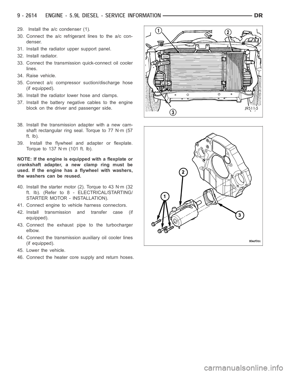
29. Install the a/c condenser (1).
30. Connect the a/c refrigerant lines to the a/c con-
denser.
31. Install the radiator upper support panel.
32. Install radiator.
33. Connect the transmission quick-connect oil cooler
lines.
34. Raise vehicle.
35. Connect a/c compressor suction/discharge hose
(if equipped).
36. Install the radiator lower hose and clamps.
37. Install the battery negative cables to the engine
block on the driver and passenger side.
38. Install the transmission adapter with a new cam-
shaft rectangular ring seal. Torque to 77 Nꞏm (57
ft. lb).
39. Install the flywheel and adapter or flexplate.
Torque to 137 Nꞏm (101 ft. lb).
NOTE: If the engine is equipped with a flexplate or
crankshaft adapter, a new clamp ring must be
used. If the engine has a flywheel with washers,
the washers can be reused.
40. Install the starter motor (2). Torque to 43 Nꞏm (32
ft. lb). (Refer to 8 - ELECTRICAL/STARTING/
STARTER MOTOR - INSTALLATION).
41. Connect engine to vehicle harness connectors.
42. Install transmission and transfer case (if
equipped).
43. Connect the exhaust pipe to the turbocharger
elbow.
44. Connect the transmission auxiliary oil cooler lines
(if equipped).
45. Lower the vehicle.
46. Connect the heater core supply and return hoses.
Page 1971 of 5267

12. Install gear housing cover (Refer to 9 - ENGINE/VALVE TIMING/GEAR HOUSING COVER - INSTALLATION).
Install front crankshaft dust seal.
13. Install the crankshaft damper with the speed indicator ring (Refer to 9- ENGINE/ENGINE BLOCK/VIBRATION
DAMPER - INSTALLATION).
14. Install the fan support/hub assembly Refer to (Refer to 7 - COOLING/ENGINE/RADIATOR FAN - INSTALLA-
TION).
15. Install the power steering pump.
16. Install accessory drive belt tensioner. Torque bolt to 43 Nꞏm (32 ft. lbs.).
17. Install the accessory drive belt (Refer to 7 - COOLING/ACCESSORY DRIVE/DRIVE BELTS - INSTALLATION).
18. Install the charge air cooler (with a/c condenser and auxiliary transmission oil cooler, if equipped) and tighten
the mounting bolts to 2 Nꞏm (17 in. lbs.) torque.
19. Connect charge air cooler inlet and outlet pipes. Tighten clamps to 11 Nꞏm (95 in. lbs.) torque.
20. Install the radiator upper support panel.
21. Close radiator petcock and lower the radiator into the engine compartment. Tighten the mounting bolts to 11
Nꞏm (95 in. lbs.) torque.
22. Raise vehicle on hoist.
23. Connect radiator lower hose and install clamp.
24. Connect transmission auxiliary oil cooler lines (if equipped).
25. Lower vehicle.
26. Install the fandrive/shroud assembly. (Refer to 7 - COOLING/ENGINE/RADIATOR FAN - INSTALLATION)
27. Install the coolant recovery and windshield washer fluid reservoirs to the fan shroud.
28. Connect the coolant recovery hose to the radiator filler neck.
29. Add engine coolant (Refer to 7 - COOLING - STANDARD PROCEDURE).
30. Charge A/C system with refrigerant (if A/C equipped) (Refer to 24 - HEATING & AIR CONDITIONING/PLUMB-
ING - STANDARD PROCEDURE).
31. Connect the battery negative cables.
32. Start engine and check for engine oil and coolant leaks.
Page 2170 of 5267

DIAGNOSIS AND TESTING
CHARGE AIR COOLER SYSTEM - LEAKS
Low turbocharger boost pressure and low engine per-
formance can be caused by leaks in the charge air
cooler or plumbing. Fuel staining on the exhaust man-
ifold can also be an indication that there are leaks in
the air system. The followingprocedure outlines how
to check for leaks in the charge air cooler system.
This procedure can also be used to check for leaks in
the wastegate signal line or the wastegate canister.
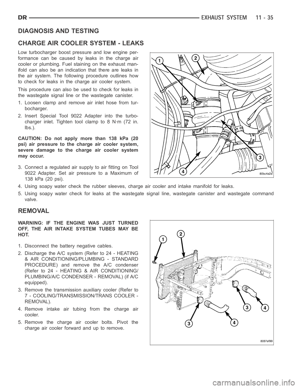
1. Loosen clamp and remove air inlet hose from tur-
bocharger.
2. Insert Special Tool 9022 Adapter into the turbo-
charger inlet. Tighten tool clamp to 8 Nꞏm (72 in.
lbs.).
CAUTION: Do not apply more than 138 kPa (20
psi) air pressure to the charge air cooler system,
severe damage to the charge air cooler system
may occur.
3. Connect a regulated air supply to air fitting on Tool
9022 Adapter. Set air pressure to a Maximum of
138 kPa (20 psi).
4. Using soapy water check the rubber sleeves, charge air cooler and intakemanifold for leaks.
5. Using soapy water check for leaks at the wastegate signal line, wastegate canister and wastegate command
valve.
REMOVAL
WARNING: IF THE ENGINE WAS JUST TURNED
OFF, THE AIR INTAKE SYSTEM TUBES MAY BE
HOT.
1. Disconnect the battery negative cables.
2. Discharge the A/C system (Refer to 24 - HEATING
& AIR CONDITIONING/PLUMBING - STANDARD
PROCEDURE) and remove the A/C condenser
(Refer to 24 - HEATING & AIR CONDITIONING/
PLUMBING/A/C CONDENSER - REMOVAL) (if A/C
equipped).
3. Remove the transmission auxiliary cooler (Refer to
7 - COOLING/TRANSMISSION/TRANS COOLER -
REMOVAL).
4. Remove intake air tubing from the charge air
cooler.
5. Remove the charge air cooler bolts. Pivot the
charge air cooler forward and up to remove.
Page 2172 of 5267

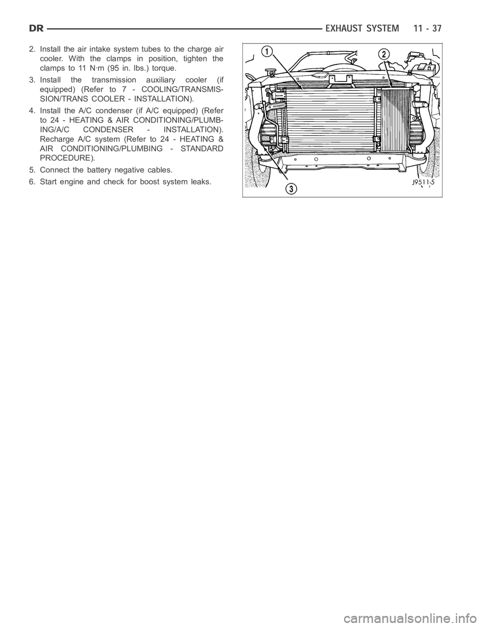
2. Install the air intake system tubes to the charge air
cooler. With the clamps in position, tighten the
clamps to 11 Nꞏm (95 in. lbs.) torque.
3. Install the transmission auxiliary cooler (if
equipped) (Refer to 7 - COOLING/TRANSMIS-
SION/TRANS COOLER - INSTALLATION).
4. Install the A/C condenser (if A/C equipped) (Refer
to 24 - HEATING & AIR CONDITIONING/PLUMB-
ING/A/C CONDENSER - INSTALLATION).
Recharge A/C system (Refer to 24 - HEATING &
AIR CONDITIONING/PLUMBING - STANDARD
PROCEDURE).
5. Connect the battery negative cables.
6. Start engine and check for boost system leaks.