Page 265 of 5267

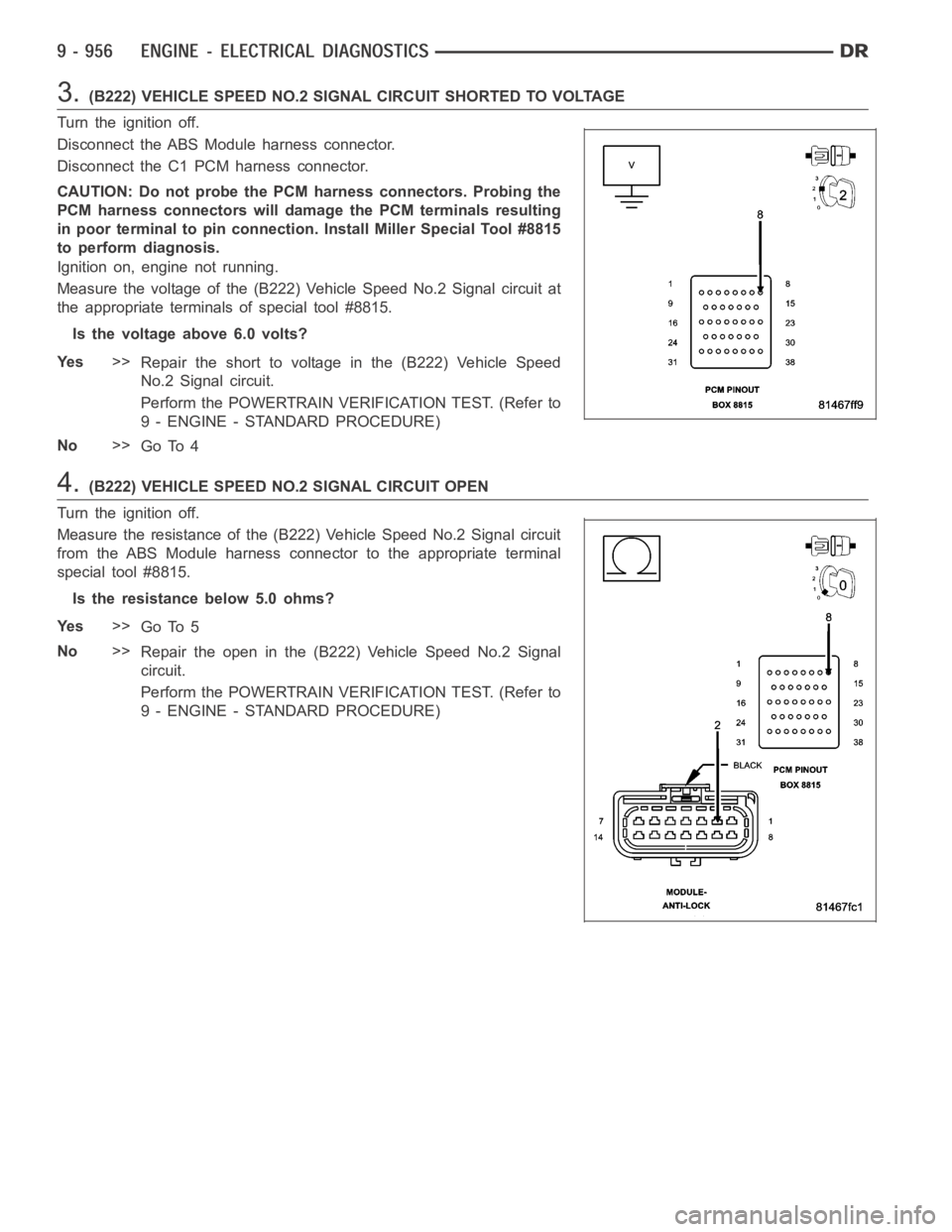
3.(B222) VEHICLE SPEED NO.2 SIGNAL CIRCUIT SHORTED TO VOLTAGE
Turn the ignition off.
Disconnect the ABS Module harness connector.
Disconnect the C1 PCM harness connector.
CAUTION: Do not probe the PCM harness connectors. Probing the
PCM harness connectors will damage the PCM terminals resulting
in poor terminal to pin connection. Install Miller Special Tool #8815
to perform diagnosis.
Ignition on, engine not running.
Measure the voltage of the (B222) Vehicle Speed No.2 Signal circuit at
the appropriate terminals of special tool #8815.
Is the voltage above 6.0 volts?
Ye s>>
Repair the short to voltage in the (B222) Vehicle Speed
No.2 Signal circuit.
Perform the POWERTRAIN VERIFICATION TEST. (Refer to
9 - ENGINE - STANDARD PROCEDURE)
No>>
Go To 4
4.(B222) VEHICLE SPEED NO.2 SIGNAL CIRCUIT OPEN
Turn the ignition off.
Measure the resistance of the (B222) Vehicle Speed No.2 Signal circuit
from the ABS Module harness connector to the appropriate terminal
special tool #8815.
Is the resistance below 5.0 ohms?
Ye s>>
Go To 5
No>>
Repair the open in the (B222) Vehicle Speed No.2 Signal
circuit.
Perform the POWERTRAIN VERIFICATION TEST. (Refer to
9 - ENGINE - STANDARD PROCEDURE)
Page 398 of 5267
When Monitored:
Ignition run time is greater than 1 second. Battery voltage between 9 and 16volts. Engine run time greater
than 3 seconds.
Set Condition:
The PCM doesn’t receive an ABS message over the CAN C circuit for 7 consecutive seconds. The circuit is
continuously monitored. One Trip fault.
Possible Causes
CAN C BUS OPEN OR SHORTED CONDITION
ABS MODULE
FCM
PCM
Refer to 8 - ELECTRICAL/ELECTRONIC CONTROL MODULES - DIAGNOSIS AND TESTING for diagnostic
procedures and for further possible causes.
Diagnostic Test
1.ACTIVE DTC
Ignition on, engine not running.
With a scan tool, read PCM DTCs.
Is the DTC active at this time?
Ye s>>
Refer to 8 - ELECTRICAL/ELECTRONIC CONTROL MODULES - DIAGNOSIS AND TESTING for diag-
nostic procedures and for further possible causes.
No>>
Refer to the INTERMITTENT CONDITION Diagnostic Procedure.
Perform the POWERTRAIN VERIFICATION TEST. (Refer to 9 - ENGINE - STANDARD PROCEDURE)
Page 409 of 5267

When Monitored:
Ignition on.
Set Condition:
The PCM doesn’t receive a vehicle speed signal from the Anti-lock brake Module over the CAN C bus. One
Trip fault.
Possible Causes
CAN C BUS CIRCUIT OPEN OR SHORTED
ANTI-LOCK BRAKE MODULE
PCM
Always perform the Pre-Diagnostic Troubleshooting procedure before proceeding. (Refer to 9 - ENGINE -
DIAGNOSIS AND TESTING) .
Theory of Operation
The PCM receives the vehicle speed signal over the CAN C bus from the Anti-lock Brake Module.
Diagnostic Test
1.ACTIVE DTC
Ignition on, engine not running.
With the scan tool read Powertrain DTCs.
Is the DTC active at this time?
Ye s>>
Go To 2
No>>
Refer to the INTERMITTENT CONDITION Diagnostic Procedure.
Perform the POWERTRAIN VERIFICATION TEST. (Refer to 9 - ENGINE - STANDARD PROCEDURE)
2.U0121-LOST COMMUNICATION WITH ABS MODULE ALSO SET
With the scan tool continue reading DTCs.
Is the U0121-LOST COMMUNICATION WITH ABS MODULE also set?
Ye s>>
Follow the diagnostics for U0121-LOST COMMUNICATION WITH ABS MODULE
Perform the POWERTRAIN VERIFICATION TEST. (Refer to 9 - ENGINE - STANDARD PROCEDURE)
No>>
Replace and program the Powertrain Control Module per Service Information.
Perform the POWERTRAIN VERIFICATION TEST. (Refer to 9 - ENGINE - STANDARD PROCEDURE)
Page 413 of 5267

When Monitored:
Ignition on.
Set Condition:
The PCM doesn’t receive a vehicle speed signal from the Anti-lock brake Module over the CAN C bus. One
Trip fault.
Possible Causes
CAN C BUS CIRCUIT OPEN OR SHORTED
ANTI-LOCK BRAKE MODULE
PCM
Always perform the Pre-Diagnostic Troubleshooting procedure before proceeding. (Refer to 9 - ENGINE -
DIAGNOSIS AND TESTING) .
Theory of Operation
The PCM receives the vehicle speed signal over the CAN C bus from the Anti-lock Brake Module.
Diagnostic Test
1.ACTIVE DTC
Ignition on, engine not running.
With the scan tool read Powertrain DTCs.
Is the DTC active at this time?
Ye s>>
Go To 2
No>>
Refer to the INTERMITTENT CONDITION Diagnostic Procedure.
Perform the POWERTRAIN VERIFICATION TEST. (Refer to 9 - ENGINE - STANDARD PROCEDURE)
2.U0121-LOST COMMUNICATION WITH ABS MODULE ALSO SET
With the scan tool continue reading DTCs.
Is the U0121-LOST COMMUNICATION WITH ABS MODULE also set?
Ye s>>
Follow the diagnostics for U0121-LOST COMMUNICATION WITH ABS MODULE
Perform the POWERTRAIN VERIFICATION TEST. (Refer to 9 - ENGINE - STANDARD PROCEDURE)
No>>
Replace and program the Powertrain Control Module per Service Information.
Perform the POWERTRAIN VERIFICATION TEST. (Refer to 9 - ENGINE - STANDARD PROCEDURE)
Page 417 of 5267

When Monitored:
Ignition on.
Set Condition:
The PCM gets an implausible signal over the CAN C circuit from the ABS Module. The circuit is continuously
monitored. One Trip fault.
Possible Causes
CAN C BUS CIRCUIT SHORTED
CAN C BUS CIRCUIT OPEN
ABS MODULE
PCM
Always perform the Pre-Diagnostic Troubleshooting procedure before proceeding. (Refer to 9 - ENGINE -
DIAGNOSIS AND TESTING).
Theory of Operation
The ABS Module sends vehicle speed information over the CAN C Bus circuit tothe PCM.
Diagnostic Test
1.ACTIVE DTC
Ignition on, engine not running.
With a scan tool, read DTCs.
Is the U1412-IMPLAUSIBLE VEHICLE SPEED SIGNAL RECEIVED active at this time?
Ye s>>
Go To 2
No>>
Refer to the INTERMITTENT CONDITION Diagnostic Procedure.
Perform the POWERTRAIN VERIFICATION TEST. (Refer to 9 - ENGINE - STANDARD PROCEDURE)
2.U0001-NO COMMUNICATION ON THE CAN C BUS CIRCUIT IS ACTIVE
Continue reading DTCs.
Is the U0001-NO COMMUNICATION ON THE CAN C BUS CIRCUIT ACTIVE at this time?
Ye s>>
Refer to the Diagnostic Procedure for the U0001-NO COMMUNICATION ON THE CANCBUSCIR-
CUIT.
No>>
Go To 3
3.ABS MODULE IS ACTIVE ON THE CAN C BUS
With the scan tool, select ECU View.
Verify that the ABS Module active on the bus.
Is the ABS Module active on the bus?
Ye s>>
Go To 4
No>>
(Refer to 8 - ELECTRICAL/ELECTRONIC CONTROL MODULES - DIAGNOSIS AND TESTING) for No
Response diagnostic procedures.
Perform BODY VERIFICATION TEST – VER 1.
Page 418 of 5267
4.ACTIVE DTCS IN THE FCM
With the scan tool, select ECU View and select FCM.
With the scan tool, read active DTCs.
Is the U0001-NO COMMUNICATION ON THE CAN C BUS CIRCUIT ACTIVE in the FCM at this time?
Ye s>>
Replace the ABS Module per Service Information.
Perform the POWERTRAIN VERIFICATION TEST. (Refer to 9 - ENGINE - STANDARD PROCEDURE)
No>>
Replace and program the Powertrain Control Module per Service Information.
Perform the POWERTRAIN VERIFICATION TEST. (Refer to 9 - ENGINE - STANDARD PROCEDURE)
Page 420 of 5267

When Monitored:
Ignition on.
Set Condition:
The PCM gets an implausible signal over the CAN C circuit from the ABS Module. The circuit is continuously
monitored. One Trip fault.
Possible Causes
VEHICLE SPEED SENSOR FAULT ACTIVE IN ANTI-LOCK BRAKE MODULE
CAN C BUS CIRCUIT SHORTED
CAN C BUS CIRCUIT OPEN
ABS MODULE
PCM
Always perform the Pre-Diagnostic Troubleshooting procedure before proceeding. (Refer to 9 - ENGINE -
DIAGNOSIS AND TESTING).
Theory of Operation
The ABS Module sends an implausible distance signal over the CAN C Bus circuit to the PCM.
Diagnostic Test
1.ACTIVE DTC
Ignition on, engine not running.
With a scan tool, read DTCs.
Is the U1417-IMPLAUSIBLE LEFT WHEEL DISTANCE SIGNAL RECEIVED active at this time?
Ye s>>
Go To 2
No>>
Refer to the INTERMITTENT CONDITION Diagnostic Procedure.
Perform the POWERTRAIN VERIFICATION TEST. (Refer to 9 - ENGINE - STANDARD PROCEDURE)
2.ABS MODULE IS ACTIVE ON THE CAN C BUS
With the scan tool, select ECU View.
Verify that the ABS Module active on the bus.
Is the ABS Module active on the bus?
Ye s>>
Go To 3
No>>
(Refer to 8 - ELECTRICAL/ELECTRONIC CONTROL MODULES - DIAGNOSIS AND TESTING) for No
Response diagnostic procedures.
Perform BODY VERIFICATION TEST – VER 1.
3.DTCS STORED OR ACTIVE IN THE ABS MODULE
Check for DTCs in the ABS Module.
Are any DTCs active or stored in the ABS Module?
Ye s>>
Refer to section 5 - BRAKES - ABS ELECTRICAL DIAGNOSTICS and perform the diagnostics for the
DTCs in the ABS Module.
Perform ABS VERIFICATION TEST – VER 1
No>>
Go to 4
Page 421 of 5267
4.ACTIVE DTCS IN THE FCM
With the scan tool, select ECU View and select FCM.
With the scan tool, read active DTCs.
AreanyCommunicationDTCsactiveintheFCMrelatingtotheABSSystem?
Ye s>>
Replace the ABS Module per Service Information.
Perform the POWERTRAIN VERIFICATION TEST. (Refer to 9 - ENGINE - STANDARD PROCEDURE)
No>>
Replace and program the Powertrain Control Module per Service Information.
Perform the POWERTRAIN VERIFICATION TEST. (Refer to 9 - ENGINE - STANDARD PROCEDURE)