2006 DODGE RAM SRT-10 ABS
[x] Cancel search: ABSPage 1484 of 5267
23. If thelift foot setsare continually used, a speed control overshoot/undershoot condition will develop.
24. To
unlearnthe overshoot/undershoot condition, the vehicle operator has to press and release the set button
while maintaining the desired set speedusing the accelerator pedal (not decelerating or accelerating).
25. Then turn the cruise control switch to the OFF position (or press the CANCEL button if equipped) after waiting
10 seconds.
26. This procedure must be performed approximately 10-15 times to completely unlearn the overshoot/undershoot
condition.
Did the Speed Control pass the above test?
Ye s>>
Repair is complete.
No>>
Check for any related Technical Service Bulletins and/or refer to the appropriate Diagnostic Procedure.
3.POWERTRAIN VERIFICATION TEST 2
1. If this vehicle is equipped with an Electronic Throttle Control system,and the APP Sensors, PCM, or Throttle
Body Assembly has been replaced use a scan tool to perform the ETC RELEARN function.
NOTE: 2. After completing the Powertrain Verification Test the Transmission Verification Test must be per-
formed.
NOTE: 3. If the PCM has been replaced and the correct VIN and mileage have notbeen programmed, a DTC
will set in the ABS Module, Airbag Module and the SKIM/SKREEM.
NOTE: 4. If the vehicle is equipped with a Sentry Key Remote Entry, Secret Key data must be updated. Refer
to the Service Information for the PCM, SKIM/SKREEM and the Transponder (ignition key) for programming
information. Using the scan tool, program the Secret Key information intothe PCM using the PCM replaced
function under the WCM menu.
5. Inspect the vehicle to make sure that all components related to the repair are properly installed and connected.
6. With the scan tool, clear DTCs.
7. Perform generator output test. Refer to the appropriate service information as necessary.
8. Start the engine and set engine speed to 2000 RPM for at least thirty seconds.
9. Cycle the ignition key off and on.
10. With the scan tool, read the DTCs.
Are any DTCs or symptoms remaining?
Ye s>>
Check for any Technical Service Bulletins and/or refer to the appropriateDiagnostic Procedure.
No>>
Repair is complete.
4.POWERTRAIN VERIFICATION TEST 3
1. Install the Miller Tool #8404 Evaporative Emission Leak Detector (EELD) according to the instructions in the pre-
vious DTC table.
2. Set the smoke/air control switch to AIR.
3. Insert the tester’s AIR supply tip (clear hose) into the appropriate calibration orifice on the tester’s control panel
(based on DTC leak size).
4. Press the remote smoke/air start button.
5. Position the red flag on the air flow meter so it is aligned with the indicator ball.
6. When the calibration is complete, release the remote button. The EELD flow meter is now calibrated in liters per
minute to the size of leak indicated by the DTC set in the PCM.
7. Install the service port adapter #8404-14 on the vehicle’s service port.
8. Connect the Air supply hose from the EELD to the vehicle.
9. Press the remote button to activate AIR flow.
NOTE: 10. Larger volume fuel tanks, lower fuel levels or if the vehicle is equipped with a Flow Management
Valve may indicate high flow and will require 4 to 5 minutes to fill.
11. Compare the flow meter indicator ball reading to the red flag.
12. ABOVE the red flag indicates a leak present.
13. BELOW the red flag indicates a sealed system.
Page 1485 of 5267
NOTE: If this vehicle is equipped with an Electronic Throttle Control system, and the APP Sensors, PCM, or
Throttle Body Assembly have been replaced, use the scan tool to perform theETC RELEARN function.
14. If the indicator ball shows a leak present, perform the smoke test indicated in the previous test and identify the
leak and repair. Perform this verification test when the repair is complete.
Didtheindicatorballindicatethealeakispresent?
Ye s>>
Repeat the DTC test to identify the leak and repair.
No>>
Repair is complete.
5.POWERTRAIN VERIFICATION TEST 4
NOTE: 1. After completing the Powertrain Verification Test the Transmission Verification Test must be per-
formed.
NOTE: 2. If the PCM has been replaced and the correct VIN and mileage have notbeen programmed, a DTC
will set in the ABS Module, Airbag Module and the SKIM/SKREEM.
NOTE: 3. If the vehicle is equipped with a Sentry Key Remote Entry, Secret Key data must be updated. Refer
to the Service Information for the PCM, SKIM/SKREEM and the Transponder (ignition key) for programming
information. Using the scan tool, program the Secret Key information intothe PCM using the PCM replaced
function under the WCM menu.
NOTE: 4. If this vehicle is equipped with an Electronic Throttle Control system, and the APP Sensors, PCM,
or Throttle Body Assembly have been replaced, use the scan tool to perform the ETC RELEARN function.
NOTE: 5. When replacing an O2 Sensor, the PCM RAM memory must be cleared, either by disconnecting the
PCM C1 connector or momentarily disconnecting the Battery negative terminal.
6. The NGC learns the characteristics of each O2 heater element and these old values should be cleared when
installing a new O2 sensor. The customermay experience driveability issues if this is not performed.
7. Inspect the vehicle to make sure that all engine components are properlyinstalled and connected. Reassemble
and reconnect components as necessary.
8. Connect the scan tool to the data link connector.
9. Make sure the fuel tank has at least a quarter tank of fuel. Turn off all accessories.
10. If the Catalyst was replaced, with the scan tool go to the MiscellaneousMenu Option
Catalyst Replacedand
press enter.
11. If a Comprehensive Component DTC was repaired, perform steps 12 - 14. Ifa Major OBDII Monitor DTC was
repaired skip those steps and continue verification.
12. After the ignition has been off for at least 10 seconds, restart the vehicle and run 2 minutes.
13. With the scan tool, monitor the appropriate pre-test enabling conditions until all conditions have been met. Once
the conditions have been met, switch screen to the appropriate OBDII monitor, (Audible beeps when the monitor is
running).
14. If the repaired OBDII trouble code has reset or was seen in the monitor while on the road test, the repair is not
complete. Check for any related technical service bulletins or flash updates and return to Engine Electrical Diag-
nostic List.
15. If the conditions cannot be duplicated, erase all DTCs with the Scan tool.
16. If another DTC has set, return to the Engine Electrical Diagnostic Listand follow the path specified for that DTC.
Did the OBDII Monitor run successfully and has the Good Trip Counter changed to one or more?
Ye s>>
Repair is complete.
No>>
Check for any related Technical Service Bulletins and/or refer to the appropriate Diagnostic Procedure.
Page 1496 of 5267
MoparGasket Maker is an anaerobic type gasket material. The material cures in the absence of air when
squeezed between two metallic surfaces. It will not cure if left in the uncovered tube. The anaerobic material is for
use between two machined surfaces. Do not use on flexible metal flanges.
MOPAR
GASKET SEALANT
Mopar
Gasket Sealant is a slow drying, permanently soft sealer. This material isrecommended for sealing
threaded fittings and gaskets against leakage of oil and coolant. Can be used on threaded and machined parts
under all temperatures. This material is used on engines with multi-layersteel (MLS) cylinder head gaskets. This
material also will prevent corrosion. Mopar
Gasket Sealant is available in a 13 oz. aerosol can or 4oz./16 oz. can
w/applicator.
FORM-IN-PLACE GASKET AND SEALER APPLICATION
Assembling parts using a form-in-place gasket requires care but it’s easier than using precut gaskets.
Mopar
Gasket Maker material should be applied sparingly 1 mm (0.040 in.) diameter or less of sealant to one
gasket surface. Be certain the material surrounds each mounting hole. Excess material can easily be wiped off.
Components should be torqued in place within 15 minutes. The use of a locating dowel is recommended during
assembly to prevent smearing material off the location.
Mopar
Engine RTV GEN II or ATF RTV gasket material should be applied in a continuous bead approximately 3
mm (0.120 in.) in diameter. All mounting holes must be circled. For corner sealing, a 3.17 or 6.35 mm (1/8 or 1/4 in.)
drop is placed in the center of the gasket contact area. Uncured sealant maybe removed with a shop towel. Com-
ponents should be torqued in place while the sealant is still wet to the touch (within 10 minutes). The usage of a
locating dowel is recommended during assembly to prevent smearing material off the location.
Mopar
Gasket Sealant in an aerosol can should be applied using a thin, even coat sprayed completely over both
surfaces to be joined, and both sides of a gasket. Then proceed with assembly. Material in a can w/applicator can
be brushed on evenly over the sealing surfaces. Material in an aerosol can shouldbeusedonengineswithmulti-
layer steel gaskets.
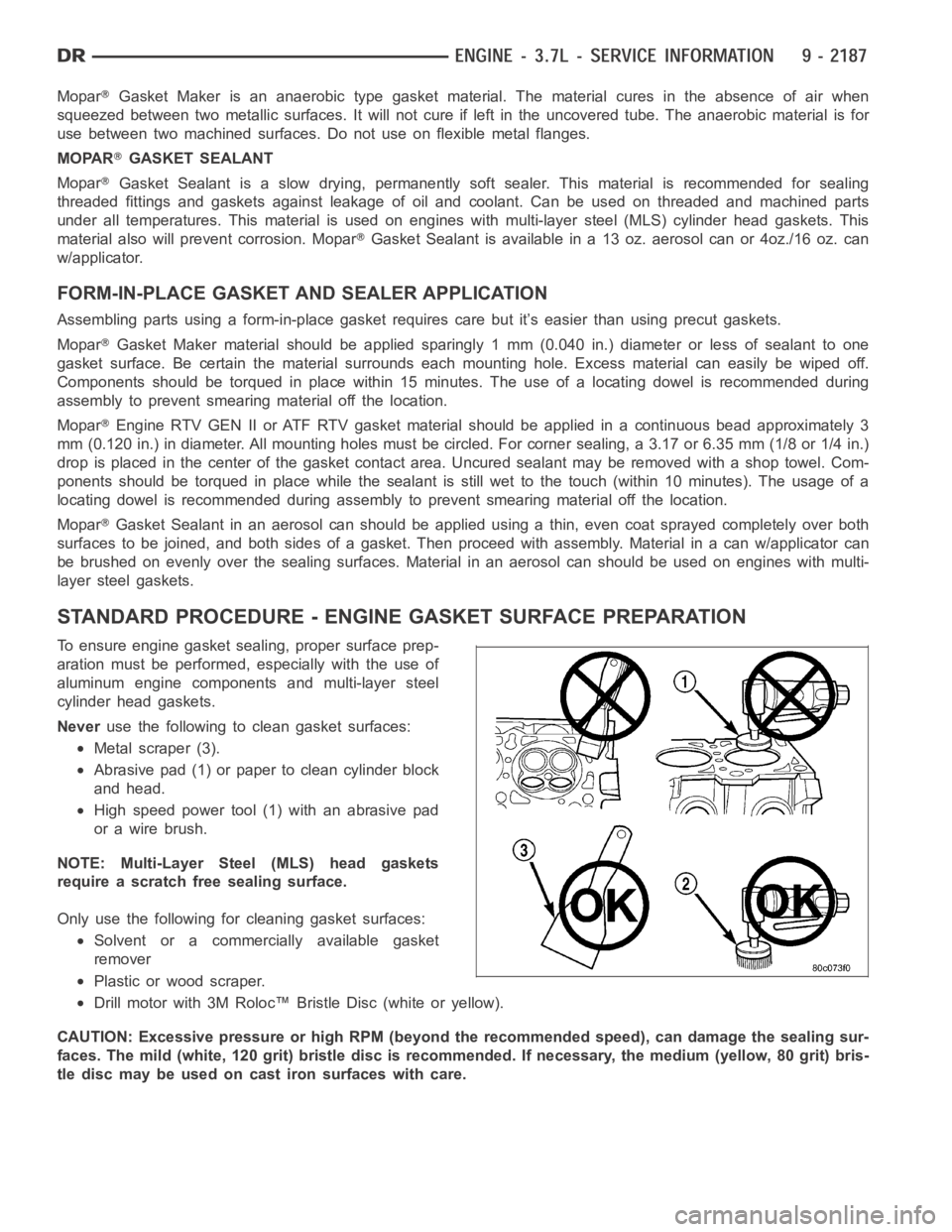
STANDARD PROCEDURE - ENGINE GASKET SURFACE PREPARATION
To ensure engine gasket sealing, proper surface prep-
aration must be performed, especially with the use of
aluminum engine components and multi-layer steel
cylinder head gaskets.
Neveruse the following to clean gasket surfaces:
Metal scraper (3).
Abrasive pad (1) or paper to clean cylinder block
and head.
High speed power tool (1) with an abrasive pad
orawirebrush.
NOTE: Multi-Layer Steel (MLS) head gaskets
require a scratch free sealing surface.
Only use the following for cleaning gasket surfaces:
Solvent or a commercially available gasket
remover
Plastic or wood scraper.
Drill motor with 3M Roloc™ Bristle Disc (white or yellow).
CAUTION: Excessive pressure or high RPM (beyond the recommended speed), can damage the sealing sur-
faces. The mild (white, 120 grit) bristle disc is recommended. If necessary, the medium (yellow, 80 grit) bris-
tle disc may be used on cast iron surfaces with care.
Page 1498 of 5267
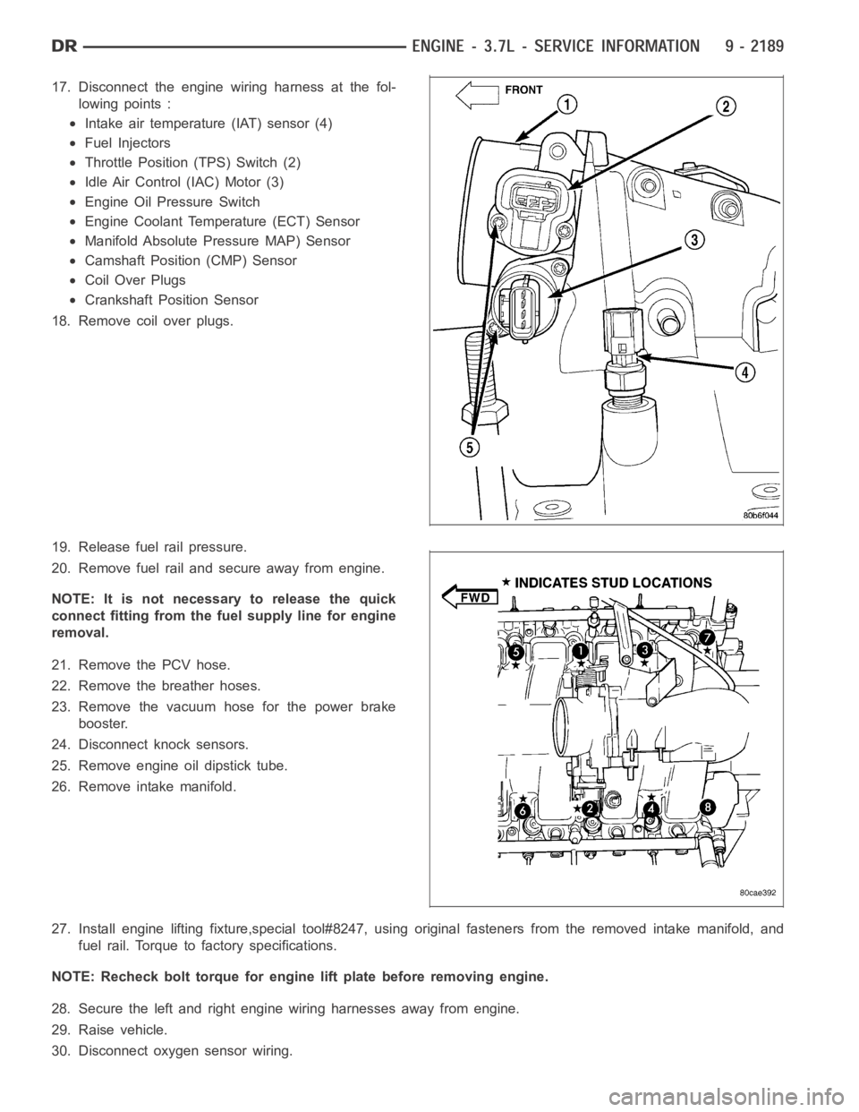
17. Disconnect the engine wiring harness at the fol-
lowing points :
Intake air temperature (IAT) sensor (4)
Fuel Injectors
Throttle Position (TPS) Switch (2)
Idle Air Control (IAC) Motor (3)
Engine Oil Pressure Switch
Engine Coolant Temperature (ECT) Sensor
Manifold Absolute Pressure MAP) Sensor
Camshaft Position (CMP) Sensor
Coil Over Plugs
Crankshaft Position Sensor
18. Remove coil over plugs.
19. Release fuel rail pressure.
20. Remove fuel rail and secure away from engine.
NOTE: It is not necessary to release the quick
connect fitting from the fuel supply line for engine
removal.
21. Remove the PCV hose.
22. Remove the breather hoses.
23. Remove the vacuum hose for the power brake
booster.
24. Disconnect knock sensors.
25. Remove engine oil dipstick tube.
26. Remove intake manifold.
27. Install engine lifting fixture,special tool#8247, using original fasteners from the removed intake manifold, and
fuel rail. Torque to factory specifications.
NOTE: Recheck bolt torque for engine lift plate before removing engine.
28. Secure the left and right engine wiring harnesses away from engine.
29. Raise vehicle.
30. Disconnect oxygen sensor wiring.
Page 1503 of 5267
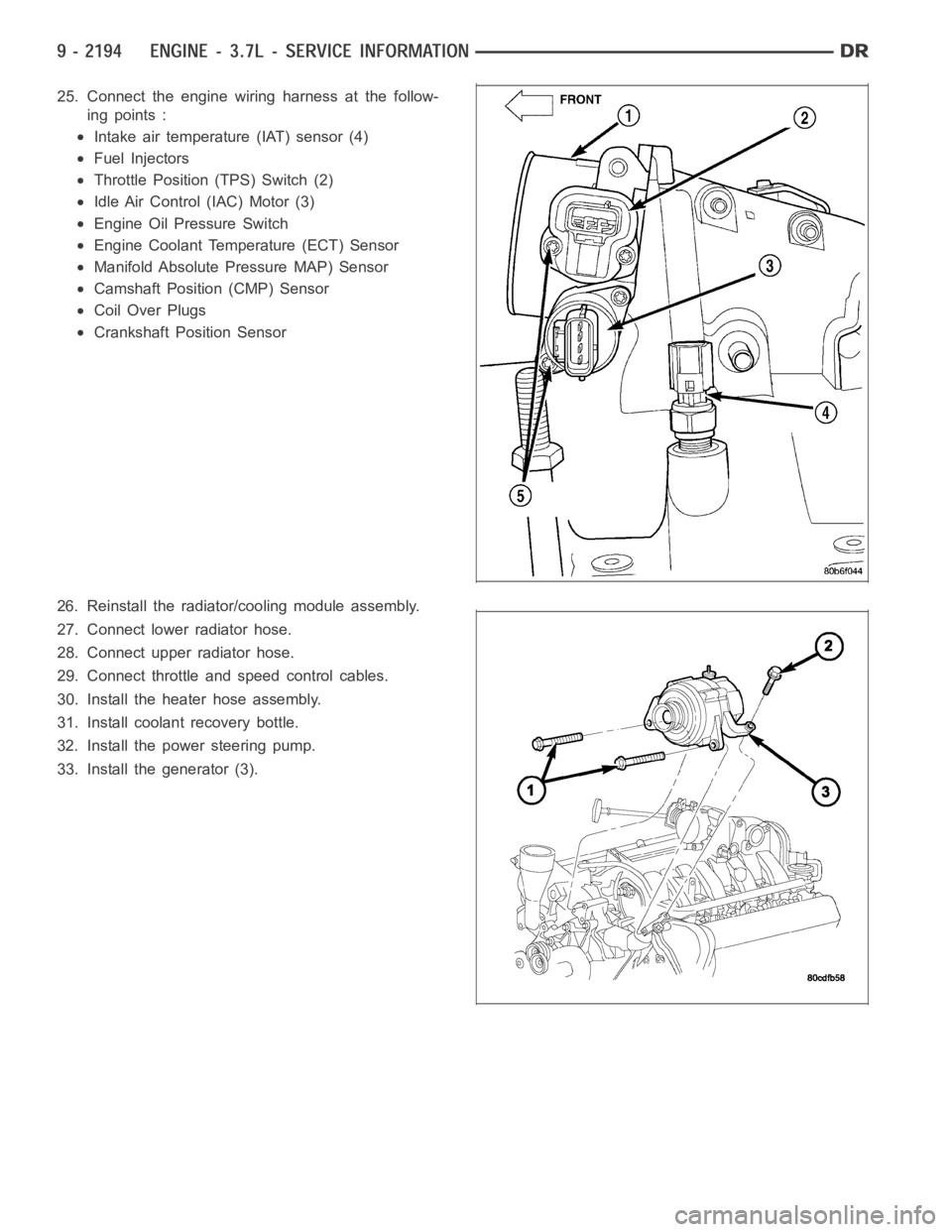
25. Connect the engine wiring harness at the follow-
ing points :
Intake air temperature (IAT) sensor (4)
Fuel Injectors
Throttle Position (TPS) Switch (2)
Idle Air Control (IAC) Motor (3)
Engine Oil Pressure Switch
Engine Coolant Temperature (ECT) Sensor
Manifold Absolute Pressure MAP) Sensor
Camshaft Position (CMP) Sensor
Coil Over Plugs
Crankshaft Position Sensor
26. Reinstall the radiator/cooling module assembly.
27. Connect lower radiator hose.
28. Connect upper radiator hose.
29. Connect throttle and speed control cables.
30. Install the heater hose assembly.
31. Install coolant recovery bottle.
32. Install the power steering pump.
33. Install the generator (3).
Page 1515 of 5267
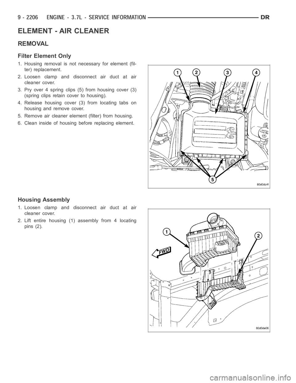
ELEMENT - AIR CLEANER
REMOVAL
Filter Element Only
1. Housing removal is not necessary for element (fil-
ter) replacement.
2. Loosen clamp and disconnect air duct at air
cleaner cover.
3. Pry over 4 spring clips (5) from housing cover (3)
(spring clips retain cover to housing).
4. Release housing cover (3) from locating tabs on
housing and remove cover.
5. Remove air cleaner element (filter) from housing.
6. Clean inside of housing before replacing element.
Housing Assembly
1. Loosen clamp and disconnect air duct at air
cleaner cover.
2. Lift entire housing (1) assembly from 4 locating
pins (2).
Page 1516 of 5267
INSTALLATION
1. Install filter element into housing.
2. Position housing cover into housing locating tabs.
3. Pry up 4 spring clips and lock cover to housing.
4. Install air duct to air cleaner cover and tighten hose clamp to 3 Nꞏm (30 in.lbs.)torque.
5. If any other hose clamps were removed from air intake system, tighten themto3.4Nꞏm(30in.lbs.)torque.
6. If any bolts were removed from air resonator housing or air intake tubing, tighten them to 4.5 Nꞏm (40 in. lbs.)
torque.
Page 1560 of 5267
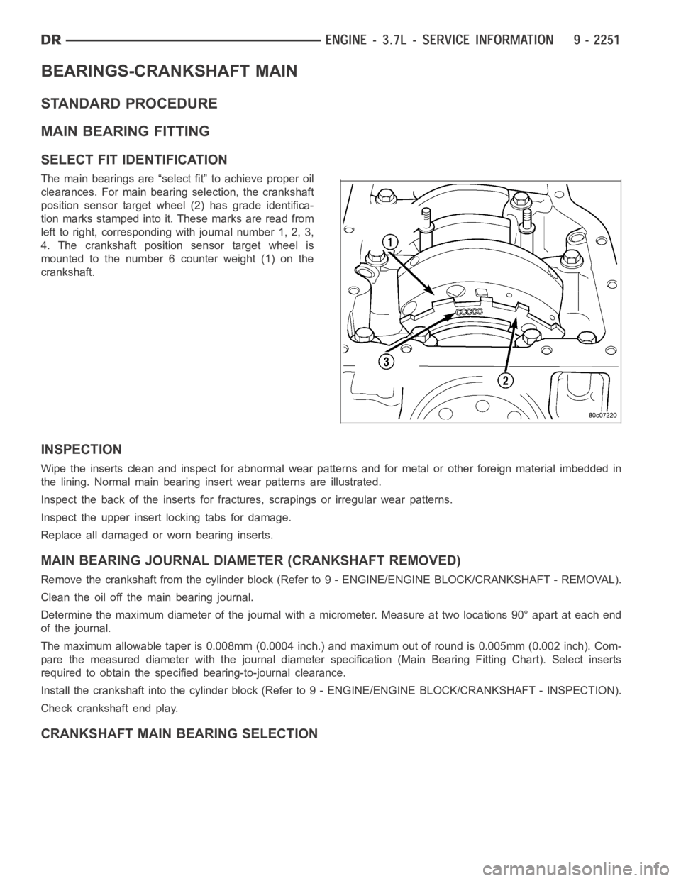
BEARINGS-CRANKSHAFT MAIN
STANDARD PROCEDURE
MAIN BEARING FITTING
SELECT FIT IDENTIFICATION
The main bearings are “select fit” to achieve proper oil
clearances. For main bearing selection, the crankshaft
position sensor target wheel (2) has grade identifica-
tion marks stamped into it. These marks are read from
left to right, corresponding with journal number 1, 2, 3,
4. The crankshaft position sensor target wheel is
mounted to the number 6 counter weight (1) on the
crankshaft.
INSPECTION
Wipe the inserts clean and inspect for abnormal wear patterns and for metalor other foreign material imbedded in
the lining. Normal main bearing insert wear patterns are illustrated.
Inspect the back of the inserts for fractures, scrapings or irregular wearpatterns.
Inspect the upper insert locking tabs for damage.
Replace all damaged or worn bearing inserts.
MAIN BEARING JOURNAL DIAMETER (CRANKSHAFT REMOVED)
Remove the crankshaft from the cylinder block (Refer to 9 - ENGINE/ENGINE BLOCK/CRANKSHAFT - REMOVAL).
Clean the oil off the main bearing journal.
Determine the maximum diameter of the journal with a micrometer. Measure at two locations 90° apart at each end
of the journal.
The maximum allowable taper is 0.008mm (0.0004 inch.) and maximum out of round is 0.005mm (0.002 inch). Com-
pare the measured diameter with the journal diameter specification (MainBearing Fitting Chart). Select inserts
required to obtain the specified bearing-to-journal clearance.
Install the crankshaft into the cylinder block (Refer to 9 - ENGINE/ENGINEBLOCK/CRANKSHAFT - INSPECTION).
Check crankshaft end play.
CRANKSHAFT MAIN BEARING SELECTION