Page 2252 of 5267
6. Perform fuel pressure release procedure. Refer to
Fuel Pressure Release Procedure.
7. Disconnect negative battery cable from battery.
8. Clean fitting of any foreign material before disas-
sembly.
9.2–Button Type Fitting:This type of fitting (1) is
equipped with a push-button located on each side
of quick-connect fitting (2). Press on both buttons
simultaneously for removal. Special tools are not
required for disconnection.
10.Pinch-Type Fitting:This fitting (1) is equipped
with two finger tabs (2). Pinch both tabs together
while removing fitting. Special tools are not
required for disconnection.
Page 2253 of 5267

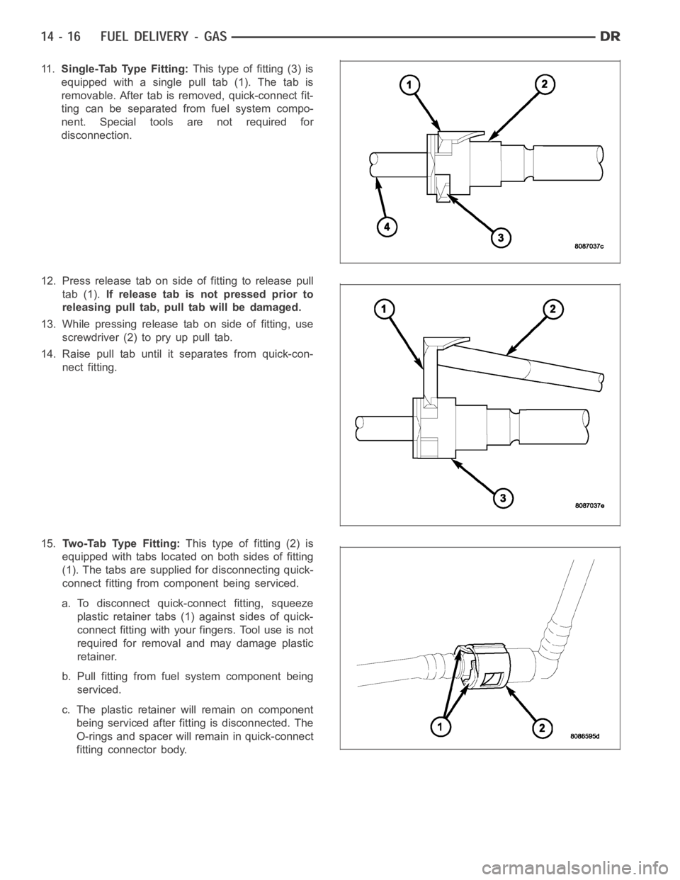
11 .Single-Tab Type Fitting:This type of fitting (3) is
equipped with a single pull tab (1). The tab is
removable. After tab is removed, quick-connect fit-
ting can be separated from fuel system compo-
nent. Special tools are not required for
disconnection.
12. Press release tab on side of fitting to release pull
tab (1).If release tab is not pressed prior to
releasing pull tab, pull tab will be damaged.
13. While pressing release tab on side of fitting, use
screwdriver (2) to pry up pull tab.
14. Raise pull tab until it separates from quick-con-
nect fitting.
15.Tw o - Ta b Ty p e F i t t i n g :This type of fitting (2) is
equipped with tabs located on both sides of fitting
(1). The tabs are supplied for disconnecting quick-
connect fitting from component being serviced.
a. To disconnect quick-connect fitting, squeeze
plastic retainer tabs (1) against sides of quick-
connect fitting with your fingers. Tool use is not
required for removal and may damage plastic
retainer.
b. Pull fitting from fuel system component being
serviced.
c. The plastic retainer will remain on component
being serviced after fitting is disconnected. The
O-rings and spacer will remain in quick-connect
fitting connector body.
Page 2280 of 5267
FILTER - INLET
REMOVAL
The fuel pump inlet filter (strainer) is located on the
bottom of the fuel pump module (1). The fuel pump
module is located inside of fuel tank.
1. Remove fuel tank. Refer to Fuel Tank Removal/In-
stallation.
2. Remove fuel pump module. Refer to Fuel Pump
Module Removal/Installation.
3. Remove filter by carefully prying 2 lock tabs (2) at
bottom of module with 2 screwdrivers. Filter is
snapped to module.
4. Clean bottom of pump module.
INSTALLATION
The fuel pump inlet filter (strainer) is located on the bottom of the fuel pump module. The fuel pump module is
located inside of fuel tank.
1. Snap new filter to bottom of module. Be sure o-ring is in correct position.
2. Install fuel pump module. Refer to Fuel Pump Module Removal/Installation.
3. Install fuel tank. Refer to Fuel Tank Removal/Installation.
Page 2313 of 5267
SENSOR-MAP
DESCRIPTION
3.7L V-6
The Manifold Absolute Pressure (MAP) sensor (2) is
mounted into the front of the intake manifold with 2
screws.
4.7L V-8
The Manifold Absolute Pressure (MAP) sensor (1) is
mounted into the front of the intake manifold with 2
screws.
Page 2314 of 5267

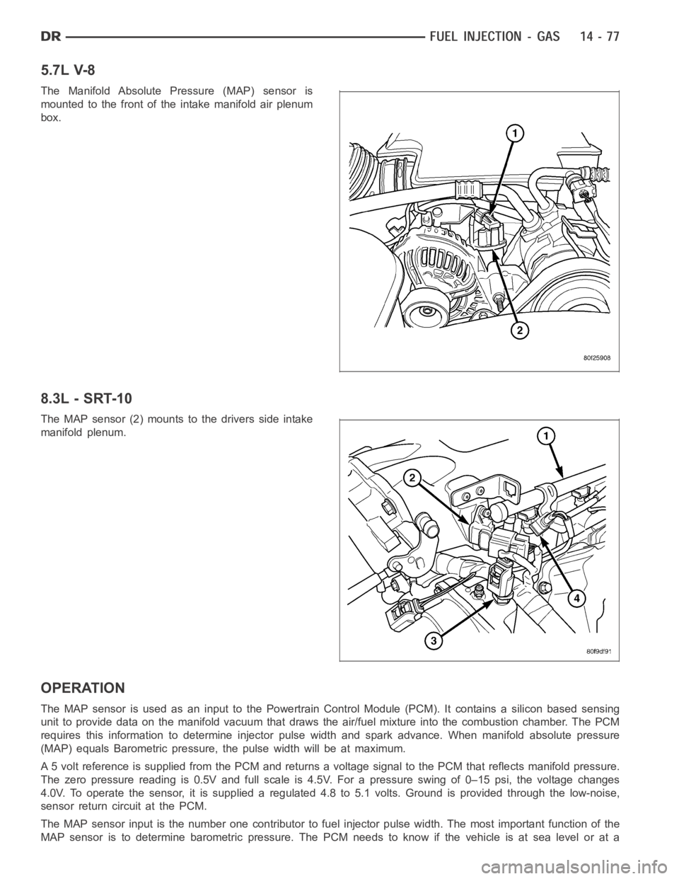
5.7L V-8
The Manifold Absolute Pressure (MAP) sensor is
mounted to the front of the intake manifold air plenum
box.
8.3L - SRT-10
The MAP sensor (2) mounts to the drivers side intake
manifold plenum.
OPERATION
The MAP sensor is used as an input to the Powertrain Control Module (PCM). Itcontains a silicon based sensing
unit to provide data on the manifold vacuum that draws the air/fuel mixtureinto the combustion chamber. The PCM
requires this information to determine injector pulse width and spark advance. When manifold absolute pressure
(MAP) equals Barometric pressure, the pulse width will be at maximum.
A 5 volt reference is supplied from the PCM and returns a voltage signal to the PCM that reflects manifold pressure.
The zero pressure reading is 0.5V and full scale is 4.5V. For a pressure swing of 0–15 psi, the voltage changes
4.0V. To operate the sensor, it is supplied a regulated 4.8 to 5.1 volts. Ground is provided through the low-noise,
sensor return circuit at the PCM.
The MAP sensor input is the number one contributor to fuel injector pulse width. The most important function of the
MAP sensor is to determine barometric pressure. The PCM needs to know if thevehicle is at sea level or at a
Page 2316 of 5267
REMOVAL
3.7L V-6
The Manifold Absolute Pressure (MAP) sensor is
mounted into the front of the intake manifold
An O-ring (2) is used to seal the sensor to the intake
manifold.
1. Disconnect electrical connector at sensor.
2. Clean area around MAP sensor.
3. Remove 2 sensor mounting screws.
4. Remove MAP sensor from intake manifold.
5. Check condition of sensor O-ring.
Page 2317 of 5267
4.7L V-8
The MAP sensor (3) is located on the front of the
intake manifold. An O-ring seals the sensor to the
intake manifold.
1. Disconnect electrical connector at sensor.
2. Clean area around MAP sensor.
3. Remove 2 sensor mounting bolts.
4. Remove MAP sensor from intake manifold.
5. Check condition of sensor O-ring.
5.7L V-8
The Manifold Absolute Pressure (MAP) sensor is
mounted to the front of the intake manifold air plenum
box.
Page 2318 of 5267
1. Disconnect electrical connector at sensor by sliding
release lock out. Press down on lock tab for
removal.
2. Rotate sensor (3) 1/4 turn counterclockwise for
removal.
3. Check condition of sensor O-ring.
8.3 L - SRT-10
The manifold absolute pressure sensor is mounted on the drivers side of theintake manifold.
1. Disconnect the electrical connector from the MAP sensor.
2. Remove MAP sensor mounting screws.
INSTALLATION
3.7L V-6
The Manifold Absolute Pressure (MAP) sensor is
mounted into the front of the intake manifold.