2006 DODGE RAM SRT-10 cruise control
[x] Cancel search: cruise controlPage 451 of 5267
POWERTRAIN VERIFICATION TEST
For a complete wiring diagramRefer to Section 8W.
Diagnostic Test
1.SELECTING THE PROPER VERIFICATION TEST
The following verification test are for different repairs. Select the appropriate Verification test for the
repair that has been completed.
Speed Control repair
Go To 2
Charging System repair
Go To 3
NVLD System repair
Go To 4
All other repairs
Go To 5
2.POWERTRAIN VERIFICATION TEST 1
NOTE: 1. If this vehicle is equipped with an Electronic Throttle Control system, and the APP Sensors, PCM,
or Throttle Body Assembly have been replaced, use the scan tool to perform the ETC RELEARN function.
NOTE: 2. After completing the Powertrain Verification Test the Transmission Verification Test must be per-
formed.
NOTE: 3. If the PCM has been replaced and the correct VIN and mileage have notbeen programmed, a DTC
will set in the ABS Module, Airbag Module and the SKIM/SKREEM.
NOTE: 4. If the vehicle is equipped with a Sentry Key Remote Entry, Secret Key data must be updated. Refer
to the Service Information for the PCM, SKIM/SKREEM and the Transponder (ignition key) for programming
information. Using the scan tool, program the Secret Key information intothe PCM using the PCM replaced
function under the WCM menu.
5. Inspect the vehicle to make sure that all engine components are properlyinstalled and connected.
6. Connect the scan tool to the data link connector and erase all codes.
7. Turn the speed control ON (if equipped, cruise light will be on).
8. Depress and release the SET Switch when the vehicle speed is greater than35 MPH. The speed control should
engage and hold the selected speed.
9. Press and hold the RESUME/ACCEL Switch. The vehicle speed should increase by at least 2 MPH.
10. Press and hold the COAST switch. The vehicle speed should decrease.
11. Using caution, press and release the brake pedal. The speed control should disengage.
12. Bring the vehicle speed back up to 35 MPH.
13. Press the RESUME/ACCEL switch. The speed control should resume the previously set speed.
14. Hold down the SET switch. The vehicle should decelerate.
15. Make sure vehicle speed is greater than 35 mph and release the SET Switch. The vehicle should adjust and set
a new vehicle speed.
16. Press and release the CANCEL switch. The speed control should disengage.
17. Bring the vehicle speed back up above 35 mph and engage speed control.
18. Turn the Speed Control Off. (Cruise light will be off). The speed control should disengage.
NOTE: OVERSHOOT/UNDERSHOOT FOLLOWING SPEED CONTROL SET.
19. If the vehicle operator repeatedly presses and releases the SET buttonwith their foot off of the accelerator
(referred to as
lift foot set), the vehicle may accelerate and exceed the desired set speed by up to 5 mph (8km/h).
20. It may also decelerate to less than the desired set speed, before finally achieving the desired set speed.
21. The Speed Control System has an adaptive strategy that compensates forvehicle-to-vehicle variations in speed
control cable lengths.
22. When the speed control is set with the vehicles operators foot off of theaccelerator pedal, the speed control
thinks there is excessive speed control cable slack and adapts accordingly.
Page 452 of 5267
23. If thelift foot setsare continually used, a speed control overshoot/undershoot condition will develop.
24. To
unlearnthe overshoot/undershoot condition, the vehicle operator has to press and release the set button
while maintaining the desired set speedusing the accelerator pedal (not decelerating or accelerating).
25. Then turn the cruise control switch to the OFF position (or press the CANCEL button if equipped) after waiting
10 seconds.
26. This procedure must be performed approximately 10-15 times to completely unlearn the overshoot/undershoot
condition.
Did the Speed Control pass the above test?
Ye s>>
Repair is complete.
No>>
Check for any related Technical Service Bulletins and/or refer to the appropriate Diagnostic Procedure.
3.POWERTRAIN VERIFICATION TEST 2
1. If this vehicle is equipped with an Electronic Throttle Control system,and the APP Sensors, PCM, or Throttle
Body Assembly has been replaced use a scan tool to perform the ETC RELEARN function.
NOTE: 2. After completing the Powertrain Verification Test the Transmission Verification Test must be per-
formed.
NOTE: 3. If the PCM has been replaced and the correct VIN and mileage have notbeen programmed, a DTC
will set in the ABS Module, Airbag Module and the SKIM/SKREEM.
NOTE: 4. If the vehicle is equipped with a Sentry Key Remote Entry, Secret Key data must be updated. Refer
to the Service Information for the PCM, SKIM/SKREEM and the Transponder (ignition key) for programming
information. Using the scan tool, program the Secret Key information intothe PCM using the PCM replaced
function under the WCM menu.
5. Inspect the vehicle to make sure that all components related to the repair are properly installed and connected.
6. With the scan tool, clear DTCs.
7. Perform generator output test. Refer to the appropriate service information as necessary.
8. Start the engine and set engine speed to 2000 RPM for at least thirty seconds.
9. Cycle the ignition key off and on.
10. With the scan tool, read the DTCs.
Are any DTCs or symptoms remaining?
Ye s>>
Check for any Technical Service Bulletins and/or refer to the appropriateDiagnostic Procedure.
No>>
Repair is complete.
4.POWERTRAIN VERIFICATION TEST 3
1. Install the Miller Tool #8404 Evaporative Emission Leak Detector (EELD) according to the instructions in the pre-
vious DTC table.
2. Set the smoke/air control switch to AIR.
3. Insert the tester’s AIR supply tip (clear hose) into the appropriate calibration orifice on the tester’s control panel
(based on DTC leak size).
4. Press the remote smoke/air start button.
5. Position the red flag on the air flow meter so it is aligned with the indicator ball.
6. When the calibration is complete, release the remote button. The EELD flow meter is now calibrated in liters per
minute to the size of leak indicated by the DTC set in the PCM.
7. Install the service port adapter #8404-14 on the vehicle’s service port.
8. Connect the Air supply hose from the EELD to the vehicle.
9. Press the remote button to activate AIR flow.
NOTE: 10. Larger volume fuel tanks, lower fuel levels or if the vehicle is equipped with a Flow Management
Valve may indicate high flow and will require 4 to 5 minutes to fill.
11. Compare the flow meter indicator ball reading to the red flag.
12. ABOVE the red flag indicates a leak present.
13. BELOW the red flag indicates a sealed system.
Page 463 of 5267

POWERTRAIN VERIFICATION TEST VER - 4 (DIESEL)
1.POWERTRAIN VERIFICATION TEST VER - 4 (DIESEL)
1. Check if any of the following conditions exist.
2. The ECM has been disconnected or replace.
3. The Battery power has been disconnected.
4. Inspect the vehicle to ensure that all engine components are properly installed and connected. Reassemble and
reconnect components as necessary.
5. With the DRBIII
,eraseDTCs.
6. If the ECM has been replaced, perform steps 11 through 13, then continue with the verification.
7. If ECM has been changed and correct VIN and mileage have not been programmed, a DTC will be set in ABS
and Air bag modules. In addition, if vehicle is equipped with a Sentry Key Immobilizer Module (SKIM), Secret Key
data must be updated to enable start.
8. For ABS and Air Bag systems: Enter correct VIN and Mileage in ECM. Erase codes in ABS and Air Bag modules.
9. For SKIM theft alarm: Connect DRBIII
to data link conn. Go to Theft Alarm, SKIM, Misc. and place SKIM in
secured access mode, by using the appropriate PIN code for this vehicle. Select Update the Secret Key data. Data
will be transferred from SKIM to PCM
10. Turn the speed control ON (if equipped, cruise light will be on).
11. Depress and release the SET Switch. If the speed control did not engage,the repair is not complete. Check for
TSBs that pertain to speed control problem and then, if necessary, return to Symptom List.
12. Depress and hold the RESUME/ACCEL Switch. If the vehicle speed did not increase by at least 2 mph, the
repair is not complete. Check for TSBs that pertain to speed control problem and then, if necessary, return to Symp-
tom List.
13. Press and hold the COAST switch. The vehicle speed should decrease. If it did not decrease, the repair is not
complete. Check for TSBs that pertain to speed control problem and then, ifnecessary, return to Symptom List.
14. Using caution, depress and release the brake pedal. If the speed control did not disengage, the repair is not
complete. Check for TSBs that pertain to speed control problem and then, ifnecessary, return to Symptom List.
15. Bring the vehicle speed back up to 35 MPH.
16. Depress the RESUME/ACCEL switch. If the speed control did not resume the previously set speed, the repair
is not complete. Check for TSBs that pertain to speed control problem and then, if necessary, return to Symptom
List.
17. Hold down the SET switch. If the vehicle did not decelerate, the repair is not complete. Check for TSBs that
pertain to speed control problem and then, if necessary, return to SymptomList.
18. Ensure vehicle speed is greater than 35 mph and release the SET Switch. If vehicle did not adjust and set a
new vehicle speed, the repair is not complete. Check for TSBs that pertain to speed control problem and then, if
necessary, return to Symptom List.
19. Depress and release the CANCEL switch. If the speed control did not disengage, the repair is not complete.
Check for TSBs that pertain to speed control problem and then, if necessary, return to Symptom List.
20. Bring the vehicle speed back up above 35 mph and engage speed control.
21. Depress the OFF switch to turn OFF, (Cruise light will be off). If the speed control did not disengage, the repair
is not complete. Check for TSBs that pertain to speed control problem and then, if necessary, return to Symptom
List.
22. If the vehicle successfully passed all of the previous tests, the speedcontrol system is now functioning as
designed. The repair is now complete.
23. NOTE: OVERSHOOT/UNDERSHOOT FOLLOWING SPEED CONTROL SET.
24. If the vehicle operator repeatedly presses and releases the SET buttonwith their foot off of the accelerator
(referred to as
lift foot set), the vehicle may accelerate and exceed the desired set speed by up to 5 mph (8km/h).
25. It may also decelerate to less than the desired set speed, before finally achieving the desired set speed.
26. The Speed Control System has an adaptive strategy that compensates forvehicle-to-vehicle variations in speed
control cable lengths.
27. When the speed control is set with the vehicles operators foot off of theaccelerator pedal, the speed control
thinks there is excessive speed control cable slack and adapts accordingly.
28. If the
lift foot setsare continually used, a speed control overshoot/undershoot condition will develop.
29. To
unlearnthe overshoot/undershoot condition, the vehicle operator has to press and release the set button
Page 464 of 5267

while maintaining the desired set speedusing the accelerator pedal (not decelerating or accelerating).
30. Then turning the cruise control switch to the OFF position (or press theCANCEL button if equipped) after wait-
ing 10 seconds.
31. This procedure must be performed approximately 10-15 times to completely unlearn the overshoot/undershoot
condition.
Did the Speed Control pass the above test?
Ye s>>
Repair is not complete, refer to appropriate symptom.
No>>
Repair is complete.
Page 1483 of 5267
POWERTRAIN VERIFICATION TEST
For a complete wiring diagramRefer to Section 8W.
Diagnostic Test
1.SELECTING THE PROPER VERIFICATION TEST
The following verification test are for different repairs. Select the appropriate Verification test for the
repair that has been completed.
Speed Control repair
Go To 2
Charging System repair
Go To 3
NVLD System repair
Go To 4
All other repairs
Go To 5
2.POWERTRAIN VERIFICATION TEST 1
NOTE: 1. If this vehicle is equipped with an Electronic Throttle Control system, and the APP Sensors, PCM,
or Throttle Body Assembly have been replaced, use the scan tool to perform the ETC RELEARN function.
NOTE: 2. After completing the Powertrain Verification Test the Transmission Verification Test must be per-
formed.
NOTE: 3. If the PCM has been replaced and the correct VIN and mileage have notbeen programmed, a DTC
will set in the ABS Module, Airbag Module and the SKIM/SKREEM.
NOTE: 4. If the vehicle is equipped with a Sentry Key Remote Entry, Secret Key data must be updated. Refer
to the Service Information for the PCM, SKIM/SKREEM and the Transponder (ignition key) for programming
information. Using the scan tool, program the Secret Key information intothe PCM using the PCM replaced
function under the WCM menu.
5. Inspect the vehicle to make sure that all engine components are properlyinstalled and connected.
6. Connect the scan tool to the data link connector and erase all codes.
7. Turn the speed control ON (if equipped, cruise light will be on).
8. Depress and release the SET Switch when the vehicle speed is greater than35 MPH. The speed control should
engage and hold the selected speed.
9. Press and hold the RESUME/ACCEL Switch. The vehicle speed should increase by at least 2 MPH.
10. Press and hold the COAST switch. The vehicle speed should decrease.
11. Using caution, press and release the brake pedal. The speed control should disengage.
12. Bring the vehicle speed back up to 35 MPH.
13. Press the RESUME/ACCEL switch. The speed control should resume the previously set speed.
14. Hold down the SET switch. The vehicle should decelerate.
15. Make sure vehicle speed is greater than 35 mph and release the SET Switch. The vehicle should adjust and set
a new vehicle speed.
16. Press and release the CANCEL switch. The speed control should disengage.
17. Bring the vehicle speed back up above 35 mph and engage speed control.
18. Turn the Speed Control Off. (Cruise light will be off). The speed control should disengage.
NOTE: OVERSHOOT/UNDERSHOOT FOLLOWING SPEED CONTROL SET.
19. If the vehicle operator repeatedly presses and releases the SET buttonwith their foot off of the accelerator
(referred to as
lift foot set), the vehicle may accelerate and exceed the desired set speed by up to 5 mph (8km/h).
20. It may also decelerate to less than the desired set speed, before finally achieving the desired set speed.
21. The Speed Control System has an adaptive strategy that compensates forvehicle-to-vehicle variations in speed
control cable lengths.
22. When the speed control is set with the vehicles operators foot off of theaccelerator pedal, the speed control
thinks there is excessive speed control cable slack and adapts accordingly.
Page 1484 of 5267
23. If thelift foot setsare continually used, a speed control overshoot/undershoot condition will develop.
24. To
unlearnthe overshoot/undershoot condition, the vehicle operator has to press and release the set button
while maintaining the desired set speedusing the accelerator pedal (not decelerating or accelerating).
25. Then turn the cruise control switch to the OFF position (or press the CANCEL button if equipped) after waiting
10 seconds.
26. This procedure must be performed approximately 10-15 times to completely unlearn the overshoot/undershoot
condition.
Did the Speed Control pass the above test?
Ye s>>
Repair is complete.
No>>
Check for any related Technical Service Bulletins and/or refer to the appropriate Diagnostic Procedure.
3.POWERTRAIN VERIFICATION TEST 2
1. If this vehicle is equipped with an Electronic Throttle Control system,and the APP Sensors, PCM, or Throttle
Body Assembly has been replaced use a scan tool to perform the ETC RELEARN function.
NOTE: 2. After completing the Powertrain Verification Test the Transmission Verification Test must be per-
formed.
NOTE: 3. If the PCM has been replaced and the correct VIN and mileage have notbeen programmed, a DTC
will set in the ABS Module, Airbag Module and the SKIM/SKREEM.
NOTE: 4. If the vehicle is equipped with a Sentry Key Remote Entry, Secret Key data must be updated. Refer
to the Service Information for the PCM, SKIM/SKREEM and the Transponder (ignition key) for programming
information. Using the scan tool, program the Secret Key information intothe PCM using the PCM replaced
function under the WCM menu.
5. Inspect the vehicle to make sure that all components related to the repair are properly installed and connected.
6. With the scan tool, clear DTCs.
7. Perform generator output test. Refer to the appropriate service information as necessary.
8. Start the engine and set engine speed to 2000 RPM for at least thirty seconds.
9. Cycle the ignition key off and on.
10. With the scan tool, read the DTCs.
Are any DTCs or symptoms remaining?
Ye s>>
Check for any Technical Service Bulletins and/or refer to the appropriateDiagnostic Procedure.
No>>
Repair is complete.
4.POWERTRAIN VERIFICATION TEST 3
1. Install the Miller Tool #8404 Evaporative Emission Leak Detector (EELD) according to the instructions in the pre-
vious DTC table.
2. Set the smoke/air control switch to AIR.
3. Insert the tester’s AIR supply tip (clear hose) into the appropriate calibration orifice on the tester’s control panel
(based on DTC leak size).
4. Press the remote smoke/air start button.
5. Position the red flag on the air flow meter so it is aligned with the indicator ball.
6. When the calibration is complete, release the remote button. The EELD flow meter is now calibrated in liters per
minute to the size of leak indicated by the DTC set in the PCM.
7. Install the service port adapter #8404-14 on the vehicle’s service port.
8. Connect the Air supply hose from the EELD to the vehicle.
9. Press the remote button to activate AIR flow.
NOTE: 10. Larger volume fuel tanks, lower fuel levels or if the vehicle is equipped with a Flow Management
Valve may indicate high flow and will require 4 to 5 minutes to fill.
11. Compare the flow meter indicator ball reading to the red flag.
12. ABOVE the red flag indicates a leak present.
13. BELOW the red flag indicates a sealed system.
Page 2035 of 5267
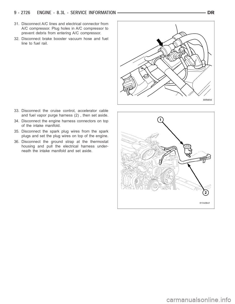
31. Disconnect A/C lines and electrical connector from
A/C compressor. Plug holes in A/C compressor to
prevent debris from entering A/C compressor.
32. Disconnect brake booster vacuum hose and fuel
line to fuel rail.
33. Disconnect the cruise control, accelerator cable
and fuel vapor purge harness (2) , then set aside.
34. Disconnect the engine harness connectors on top
of the intake manifold.
35. Disconnect the spark plug wires from the spark
plugs and set the plug wires on top of the engine.
36. Disconnect the ground strap at the thermostat
housing and pull the electrical harness under-
neath the intake manifold and set aside.
Page 2038 of 5267
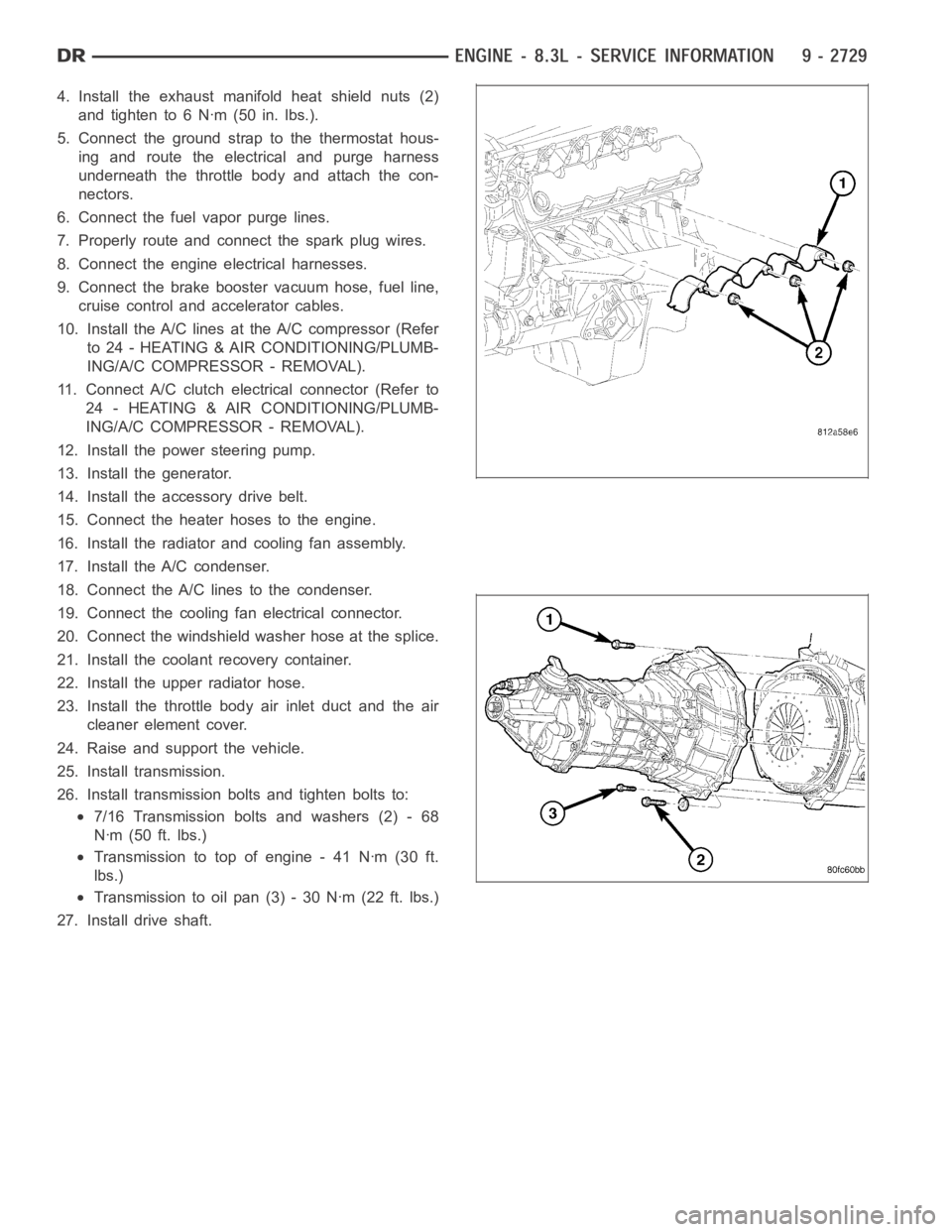
4. Install the exhaust manifold heat shield nuts (2)
and tighten to 6 Nꞏm (50 in. lbs.).
5. Connect the ground strap to the thermostat hous-
ing and route the electrical and purge harness
underneath the throttle body and attach the con-
nectors.
6. Connect the fuel vapor purge lines.
7. Properly route and connect the spark plug wires.
8. Connect the engine electrical harnesses.
9. Connect the brake booster vacuum hose, fuel line,
cruise control and accelerator cables.
10. Install the A/C lines at the A/C compressor (Refer
to 24 - HEATING & AIR CONDITIONING/PLUMB-
ING/A/C COMPRESSOR - REMOVAL).
11. Connect A/C clutch electrical connector (Refer to
24 - HEATING & AIR CONDITIONING/PLUMB-
ING/A/C COMPRESSOR - REMOVAL).
12. Install the power steering pump.
13. Install the generator.
14. Install the accessory drive belt.
15. Connect the heater hoses to the engine.
16. Install the radiator and cooling fan assembly.
17. Install the A/C condenser.
18. Connect the A/C lines to the condenser.
19. Connect the cooling fan electrical connector.
20. Connect the windshield washer hose at the splice.
21. Install the coolant recovery container.
22. Install the upper radiator hose.
23. Install the throttle body air inlet duct and the air
cleaner element cover.
24. Raise and support the vehicle.
25. Install transmission.
26. Install transmission bolts and tighten bolts to:
7/16 Transmission bolts and washers (2) - 68
Nꞏm (50 ft. lbs.)
Transmission to top of engine - 41 Nꞏm (30 ft.
lbs.)
Transmission to oil pan (3) - 30 Nꞏm (22 ft. lbs.)
27. Install drive shaft.