2006 DODGE RAM SRT-10 wheel bolt torque
[x] Cancel search: wheel bolt torquePage 1411 of 5267
3.CMP WIRE HARNESS INSPECTION
Visually inspect the related wire harness. Look for any chafed, pierced, pinched, or partially broken wires.
Visually inspect the related wire harness connectors. Look for broken, bent, pushed out, or corroded terminals.
Make sure the Crankshaft Position Sensor and the Camshaft Position Sensorare properly installed and the mount-
ing bolt(s) are torqued to specification.
Refer to any TSB that may apply.
Were any of the above conditions present?
Ye s>>
Repair as necessary
Perform POWERTRAIN VERIFICATION TEST. (Refer to 9 - ENGINE - STANDARD PROCEDURE)
No>>
Go To 4
4.TONE WHEEL/PULSE RING INSPECTION
Turn the ignition off.
Remove the Camshaft Position Sensor.
Inspect the Tone Wheel/Pulse Ring for damage, foreign material, or excessive movement.
Were any problems found?
Ye s>>
Repair or replace the Tone Wheel/Pulse Ring as necessary.
Perform POWERTRAIN VERIFICATION TEST. (Refer to 9 - ENGINE - STANDARD PROCEDURE)
No>>
Go To 5
5.CAMSHAFT POSITION SENSOR
If there are no possible causes remaining, view repair.
Repair
Replace the Camshaft Position Sensor.
Perform POWERTRAIN VERIFICATION TEST. (Refer to 9 - ENGINE - STANDARD PROCEDURE)
6.CHECKING CKP SIGNAL WITH THE SCAN TOOL LAB
Turn the ignition off.
With the scan tool as a Dual Channel Lab Scope and the Miller special tool #6801, backprobe the (K24) CKP Signal
circuit in the CKP harness connector and PCM harness connector.
WARNING: When the engine is operating, do not stand in a direct line with thefan. Do not put your hand
near the pulleys, belts, or fan. Do not wear loose clothing.
Start the engine.
Observe the lab scope screen.
Are there any irregular or missing signals?
Ye s>>
Go To 7
No>>
Go To 10
Page 1412 of 5267
7.CKP WIRE HARNESS INSPECTION
Visually inspect the related wire harness. Look for any chafed, pierced, pinched, or partially broken wires.
Visually inspect the related wire harness connectors. Look for broken, bent, pushed out, or corroded terminals.
Ensure the Crankshaft Position Sensor and the Camshaft Position Sensor are properly installed and the mounting
bolt(s) are torqued to specification.
Refer to any TSB that may apply.
Were any of the above conditions present?
Ye s>>
Repair as necessary
Perform POWERTRAIN VERIFICATION TEST. (Refer to 9 - ENGINE - STANDARD PROCEDURE)
No>>
Go To 8
8.TONE WHEEL/FLEX PLATE INSPECTION
Remove the Crankshaft Position Sensor.
Inspect the Tone Wheel/Flex Plate slots for damage, foreign material, or excessive movement.
Were any problems found?
Ye s>>
Repair or replace the Tone Wheel/Flex Plate as necessary.
Perform POWERTRAIN VERIFICATION TEST. (Refer to 9 - ENGINE - STANDARD PROCEDURE)
No>>
Go To 9
9.CRANKSHAFT POSITION SENSOR
If there are no possible causes remaining, view repair.
Repair
Replace the Crankshaft Position Sensor.
Perform POWERTRAIN VERIFICATION TEST. (Refer to 9 - ENGINE - STANDARD PROCEDURE)
10.CHECKING CKP SIGNAL WITH LAB SCOPE
NOTE: The conditions that set this DTC are not present at this time. The following test may help in identi-
fying the intermittent condition.
Turn the ignition off.
With the scan tool as a Dual Channel Lab Scope and the Miller special tool #6801, backprobe the (K24) CKP Signal
circuit in the PCM harness connector and CKP harness connector.
WARNING: When the engine is operating, do not stand in a direct line with thefan. Do not put your hand
near the pulleys, belts, or fan. Do not wear loose clothing.
Start the engine.
Carefully wiggle the related wire harness and gently tap on the CKP sensor.
Compare the Channel 1 reading to the Channel 2 reading on the lab scope screen.
Both of the readings should be the same.
Were any of the above conditions present?
Ye s>>
Repair the wiring or connector concern.
Perform POWERTRAIN VERIFICATION TEST. (Refer to 9 - ENGINE - STANDARD PROCEDURE)
No>>
Te s t C o m p l e t e .
Page 1538 of 5267
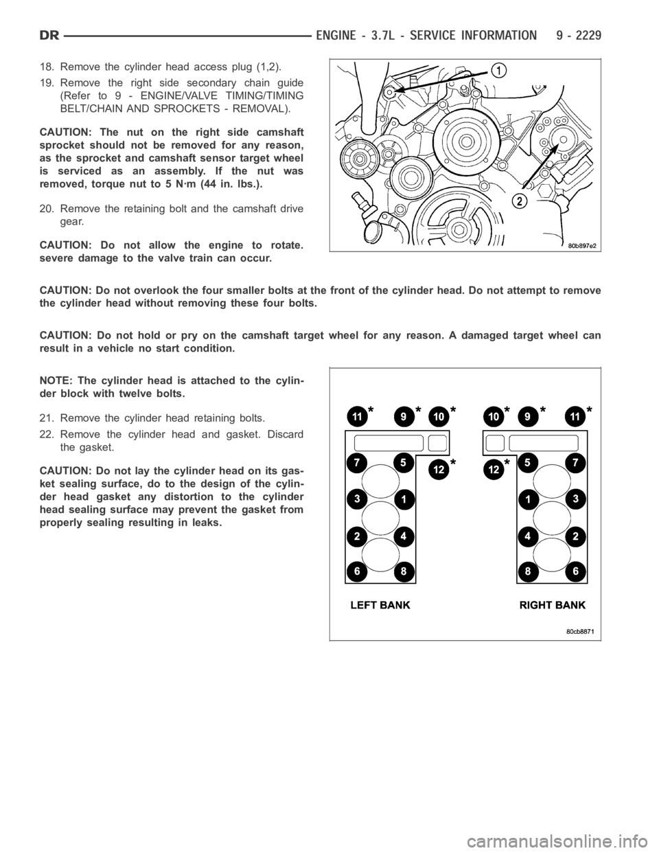
18. Remove the cylinder head access plug (1,2).
19. Remove the right side secondary chain guide
(Refer to 9 - ENGINE/VALVE TIMING/TIMING
BELT/CHAIN AND SPROCKETS - REMOVAL).
CAUTION: The nut on the right side camshaft
sprocket should not be removed for any reason,
as the sprocket and camshaft sensor target wheel
is serviced as an assembly. If the nut was
removed, torque nut to 5 Nꞏm (44 in. lbs.).
20. Remove the retaining bolt and the camshaft drive
gear.
CAUTION: Do not allow the engine to rotate.
severe damage to the valve train can occur.
CAUTION: Do not overlook the four smaller bolts at the front of the cylinderhead.Donotattempttoremove
the cylinder head without removing these four bolts.
CAUTION: Do not hold or pry on the camshaft target wheel for any reason. A damaged target wheel can
result in a vehicle no start condition.
NOTE: The cylinder head is attached to the cylin-
der block with twelve bolts.
21. Remove the cylinder head retaining bolts.
22. Remove the cylinder head and gasket. Discard
the gasket.
CAUTION: Do not lay the cylinder head on its gas-
ket sealing surface, do to the design of the cylin-
der head gasket any distortion to the cylinder
head sealing surface may prevent the gasket from
properly sealing resulting in leaks.
Page 1541 of 5267
CAUTION: The nut on the right side camshaft sprocket should not be removed for any reason, as the
sprocket and camshaft sensor target wheel is serviced as an assembly. If the nut was removed, torque nut
to 5 NM ( 60 in. lbs.).
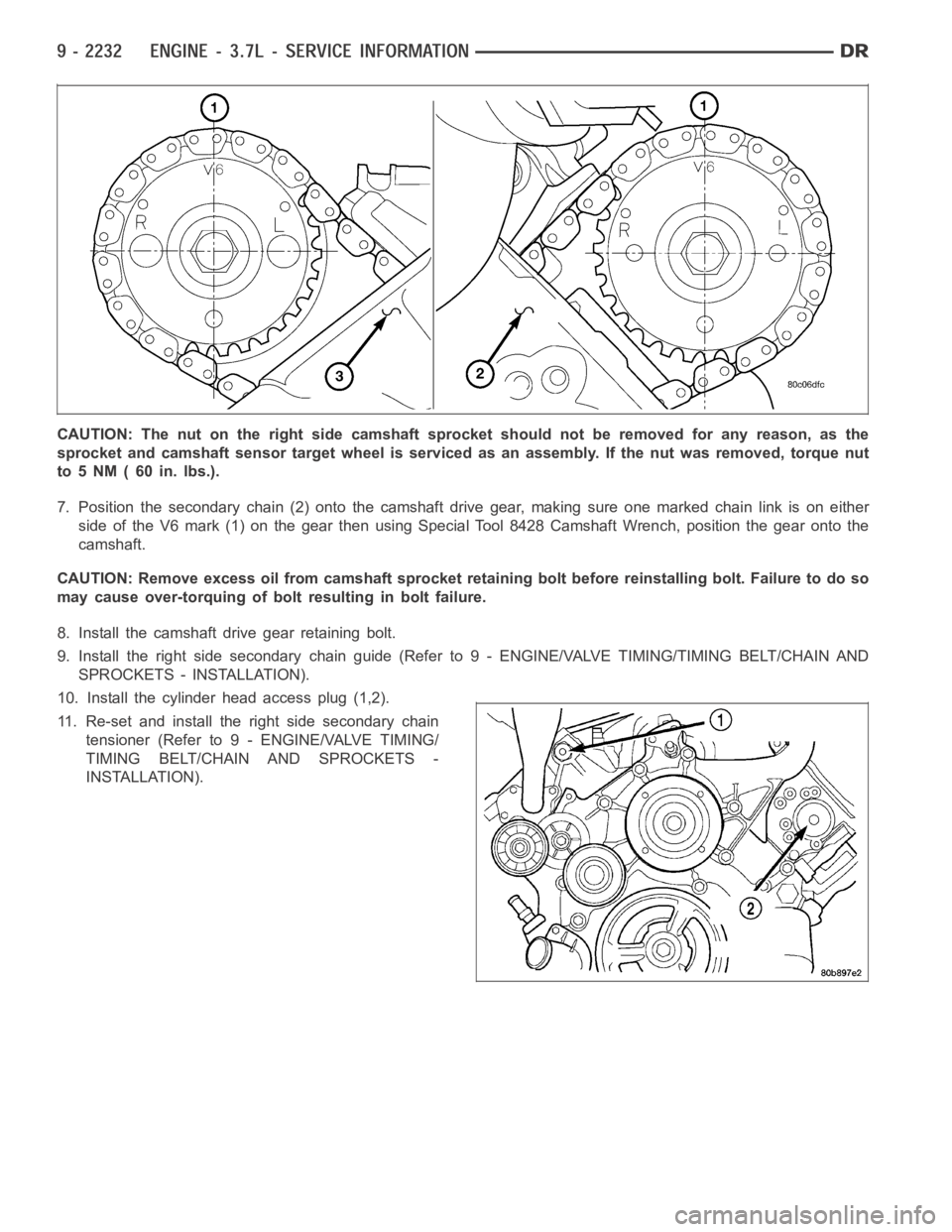
7. Position the secondary chain (2) onto the camshaft drive gear, making sure one marked chain link is on either
side of the V6 mark (1) on the gear then using Special Tool 8428 Camshaft Wrench, position the gear onto the
camshaft.
CAUTION: Remove excess oil from camshaft sprocket retaining bolt before reinstalling bolt. Failure to do so
may cause over-torquing of bolt resulting in bolt failure.
8. Install the camshaft drive gear retaining bolt.
9. Install the right side secondary chain guide (Refer to 9 - ENGINE/VALVE TIMING/TIMING BELT/CHAIN AND
SPROCKETS - INSTALLATION).
10. Install the cylinder head access plug (1,2).
11. Re-set and install the right side secondary chain
tensioner (Refer to 9 - ENGINE/VALVE TIMING/
TIMING BELT/CHAIN AND SPROCKETS -
INSTALLATION).
Page 1764 of 5267
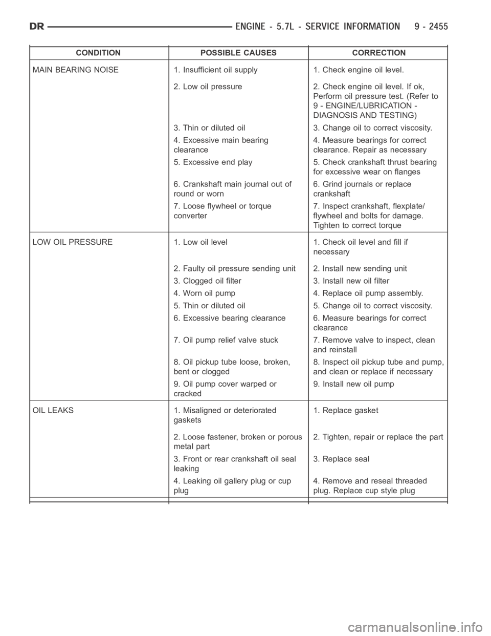
CONDITION POSSIBLE CAUSES CORRECTION
MAIN BEARING NOISE 1. Insufficient oil supply 1. Check engine oil level.
2. Low oil pressure 2. Check engine oil level. If ok,
Perform oil pressure test. (Refer to
9 - ENGINE/LUBRICATION -
DIAGNOSIS AND TESTING)
3. Thin or diluted oil 3. Change oil to correct viscosity.
4. Excessive main bearing
clearance4. Measure bearings for correct
clearance. Repair as necessary
5. Excessive end play 5. Check crankshaft thrust bearing
for excessive wear on flanges
6. Crankshaft main journal out of
round or worn6. Grind journals or replace
crankshaft
7. Loose flywheel or torque
converter7. Inspect crankshaft, flexplate/
flywheel and bolts for damage.
Tighten to correct torque
LOW OIL PRESSURE 1. Low oil level 1. Check oil level and fill if
necessary
2. Faulty oil pressure sending unit 2. Install new sending unit
3. Clogged oil filter 3. Install new oil filter
4. Worn oil pump 4. Replace oil pump assembly.
5. Thin or diluted oil 5. Change oil to correct viscosity.
6. Excessive bearing clearance 6. Measure bearings for correct
clearance
7. Oil pump relief valve stuck 7. Remove valve to inspect, clean
and reinstall
8. Oil pickup tube loose, broken,
bent or clogged8. Inspect oil pickup tube and pump,
and clean or replace if necessary
9. Oil pump cover warped or
cracked9. Install new oil pump
OIL LEAKS 1. Misaligned or deteriorated
gaskets1. Replace gasket
2. Loose fastener, broken or porous
metal part2. Tighten, repair or replace the part
3. Front or rear crankshaft oil seal
leaking3. Replace seal
4. Leaking oil gallery plug or cup
plug4. Remove and reseal threaded
plug. Replace cup style plug
Page 1781 of 5267
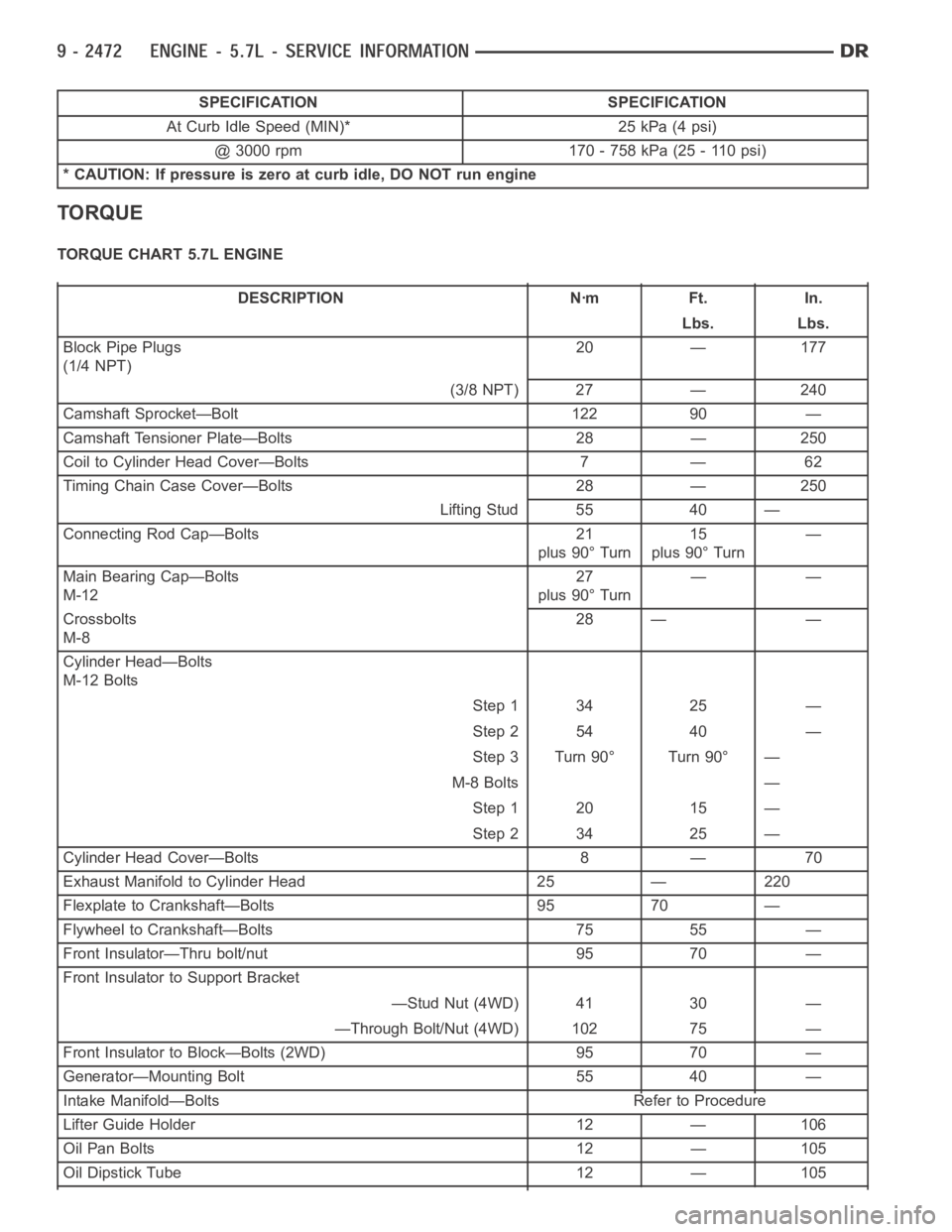
SPECIFICATION SPECIFICATION
At Curb Idle Speed (MIN)* 25 kPa (4 psi)
@ 3000 rpm 170 - 758 kPa (25 - 110 psi)
* CAUTION: If pressure is zero at curb idle, DO NOT run engine
TORQUE
TORQUE CHART 5.7L ENGINE
DESCRIPTION Nꞏm Ft. In.
Lbs. Lbs.
Block Pipe Plugs
(1/4 NPT)20 — 177
(3/8 NPT) 27 — 240
Camshaft Sprocket—Bolt 122 90 —
Camshaft Tensioner Plate—Bolts 28 — 250
Coil to Cylinder Head Cover—Bolts 7 — 62
Timing Chain Case Cover—Bolts 28 — 250
Lifting Stud 55 40 —
Connecting Rod Cap—Bolts 21
plus 90° Turn15
plus 90° Turn—
Main Bearing Cap—Bolts
M-1227
plus 90° Turn——
Crossbolts
M-828 — —
Cylinder Head—Bolts
M-12 Bolts
Step 1 34 25 —
Step 2 54 40 —
Step 3 Turn 90° Turn 90° —
M-8 Bolts —
Step 1 20 15 —
Step 2 34 25 —
Cylinder Head Cover—Bolts 8 — 70
Exhaust Manifold to Cylinder Head 25 — 220
Flexplate to Crankshaft—Bolts 95 70 —
Flywheel to Crankshaft—Bolts 75 55 —
Front Insulator—Thru bolt/nut 95 70 —
Front Insulator to Support Bracket
—Stud Nut (4WD) 41 30 —
—Through Bolt/Nut (4WD) 102 75 —
Front Insulator to Block—Bolts (2WD) 95 70 —
Generator—Mounting Bolt 55 40 —
Intake Manifold—Bolts Refer to Procedure
Lifter Guide Holder 12 — 106
Oil Pan Bolts 12 — 105
Oil Dipstick Tube 12 — 105
Page 1935 of 5267
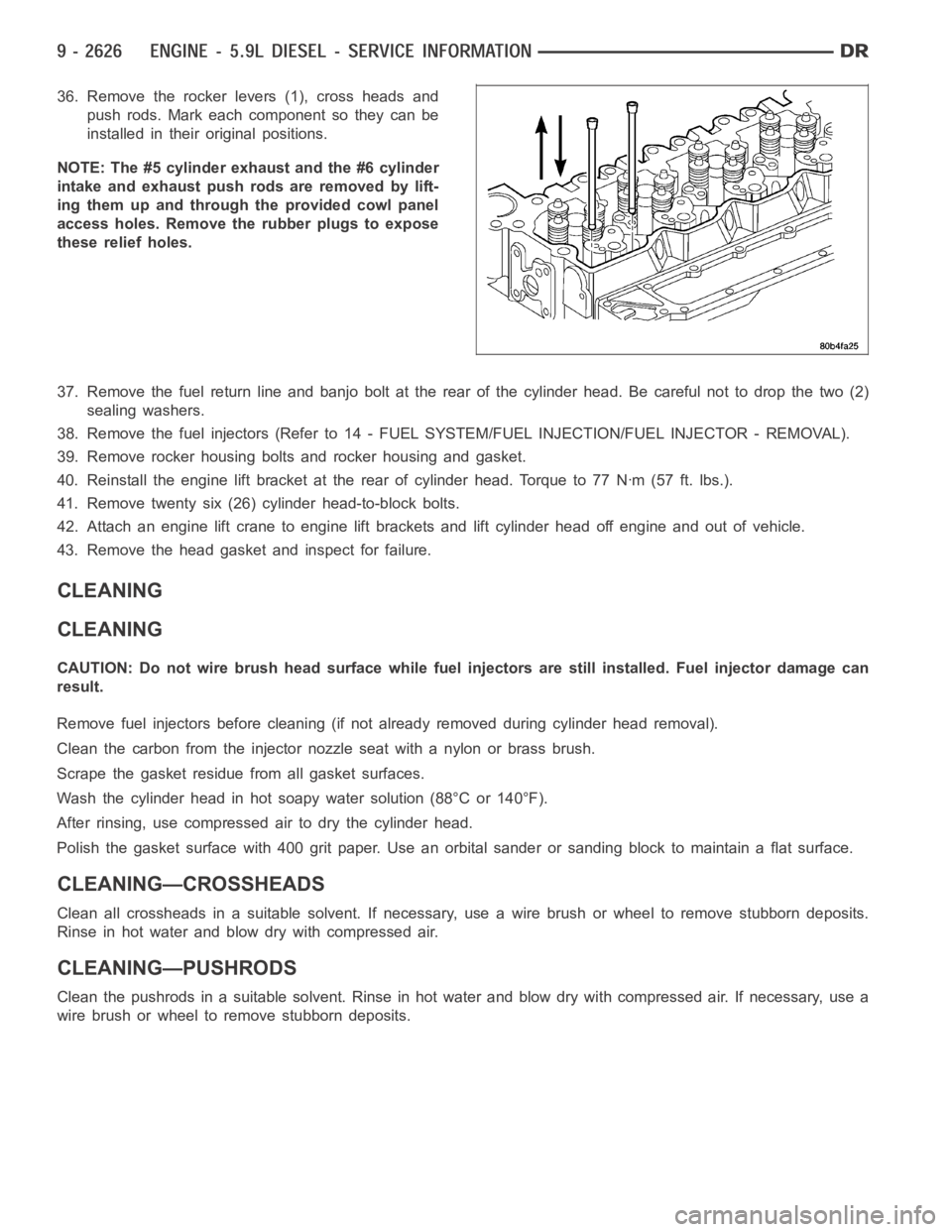
36. Remove the rocker levers (1), cross heads and
push rods. Mark each component so they can be
installed in their original positions.
NOTE: The #5 cylinder exhaust and the #6 cylinder
intake and exhaust push rods are removed by lift-
ing them up and through the provided cowl panel
access holes. Remove the rubber plugs to expose
these relief holes.
37. Remove the fuel return line and banjo bolt at the rear of the cylinder head. Be careful not to drop the two (2)
sealing washers.
38. Remove the fuel injectors (Refer to 14 - FUEL SYSTEM/FUEL INJECTION/FUEL INJECTOR - REMOVAL).
39. Remove rocker housing bolts and rocker housing and gasket.
40. Reinstall the engine lift bracket at the rear of cylinder head. Torque to77Nꞏm(57ft.lbs.).
41. Remove twenty six (26) cylinder head-to-block bolts.
42. Attach an engine lift crane to engine lift brackets and lift cylinder head off engine and out of vehicle.
43. Remove the head gasket and inspect for failure.
CLEANING
CLEANING
CAUTION: Do not wire brush head surface while fuel injectors are still installed. Fuel injector damage can
result.
Remove fuel injectors before cleaning (if not already removed during cylinder head removal).
Clean the carbon from the injector nozzle seat with a nylon or brass brush.
Scrape the gasket residuefrom all gasket surfaces.
Wash the cylinder head in hot soapy water solution (88°C or 140°F).
After rinsing, use compressed air to dry the cylinder head.
Polish the gasket surface with 400 grit paper. Use an orbital sander or sanding block to maintain a flat surface.
CLEANING—CROSSHEADS
Clean all crossheads in a suitable solvent. If necessary, use a wire brush or wheel to remove stubborn deposits.
Rinse in hot water and blow dry with compressed air.
CLEANING—PUSHRODS
Clean the pushrods in a suitable solvent. Rinse in hot water and blow dry with compressed air. If necessary, use a
wire brush or wheel to remove stubborn deposits.
Page 1979 of 5267
SEAL - CRANKSHAFT OIL - REAR
REMOVAL
1. Disconnect the battery negative cables.
2. Remove the transmission and transfer case (if
equipped).
3. Remove the clutch cover and disc (if manual trans-
mission equipped) (Refer to 6 - CLUTCH/CLUTCH
DISC - REMOVAL).
4. Remove the flywheel or converter drive plate.
5. Remove the flywheel adapter plate.
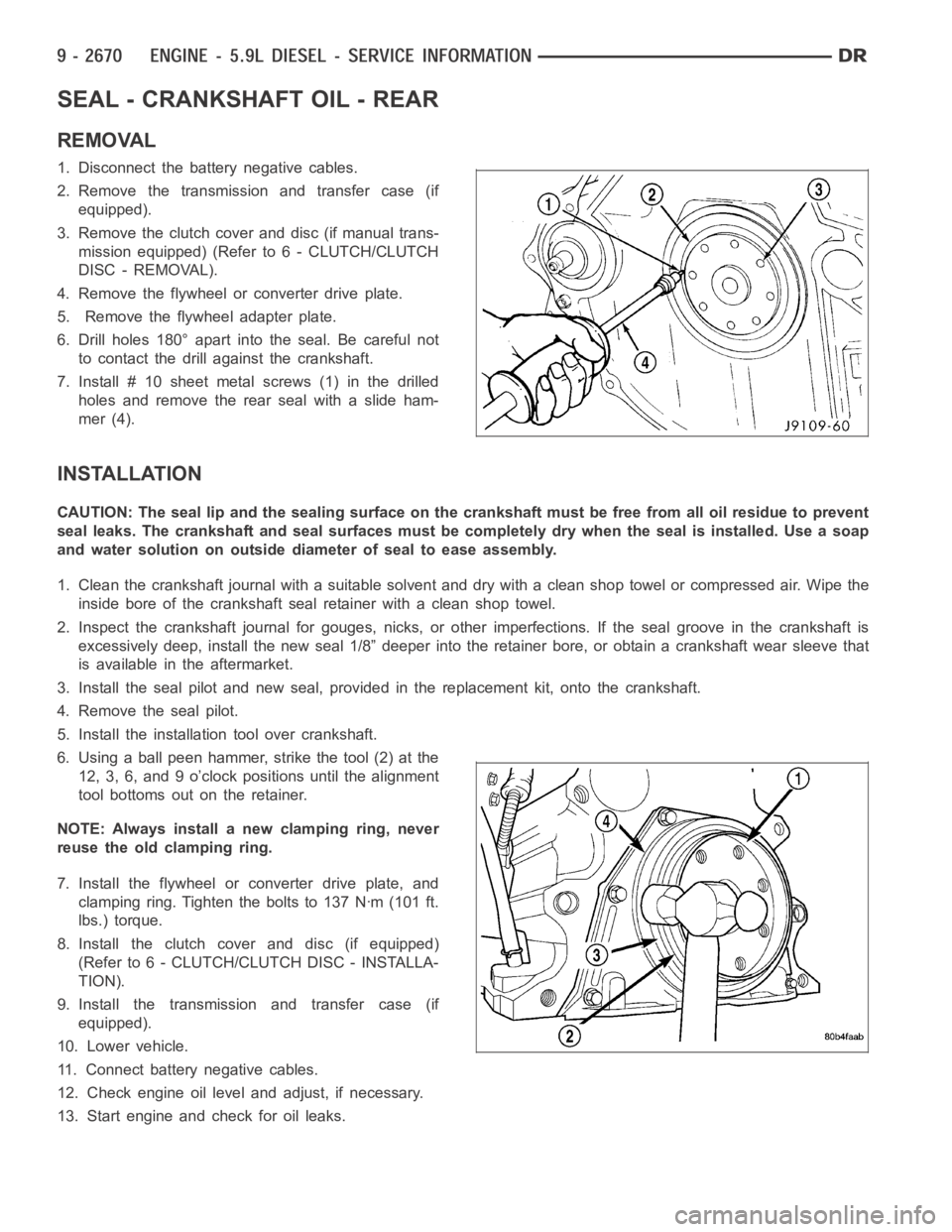
6. Drill holes 180° apart into the seal. Be careful not
to contact the drill against the crankshaft.
7. Install # 10 sheet metalscrews (1) in the drilled
holes and remove the rear seal with a slide ham-
mer (4).
INSTALLATION
CAUTION: The seal lip and the sealing surface on the crankshaft must be freefrom all oil residue to prevent
seal leaks. The crankshaft and seal surfaces must be completely dry when the seal is installed. Use a soap
and water solution on outside diameter of seal to ease assembly.
1. Clean the crankshaft journal with a suitable solvent and dry with a cleanshop towel or compressed air. Wipe the
inside bore of the crankshaft seal retainer with a clean shop towel.
2. Inspect the crankshaft journal forgouges, nicks, or other imperfections. If the seal groove in the crankshaft is
excessively deep, install the new seal 1/8” deeper into the retainer bore,or obtain a crankshaft wear sleeve that
is available in the aftermarket.
3. Install the seal pilot and new seal, provided in the replacement kit, onto the crankshaft.
4. Remove the seal pilot.
5. Install the installation tool over crankshaft.
6. Using a ball peen hammer, strike the tool (2) at the
12, 3, 6, and 9 o’clock positions until the alignment
tool bottoms out on the retainer.
NOTE: Always install a new clamping ring, never
reuse the old clamping ring.
7. Install the flywheel or converter drive plate, and
clamping ring. Tighten the bolts to 137 Nꞏm (101 ft.
lbs.) torque.
8. Install the clutch cover and disc (if equipped)
(Refer to 6 - CLUTCH/CLUTCH DISC - INSTALLA-
TION).
9. Install the transmission and transfer case (if
equipped).
10. Lower vehicle.
11. Connect battery negative cables.
12. Check engine oil level and adjust, if necessary.
13. Start engine and check for oil leaks.