2006 DODGE RAM SRT-10 wheel bolt torque
[x] Cancel search: wheel bolt torquePage 3389 of 5267

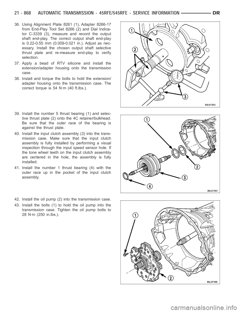
36. Using Alignment Plate 8261 (1), Adapter 8266-17
from End-Play Tool Set 8266 (2) and Dial Indica-
tor C-3339 (3), measure and record the output
shaft end-play. The correct output shaft end-play
is 0.22-0.55 mm (0.009-0.021 in.). Adjust as nec-
essary. Install the chosen output shaft selective
thrust plate and re-measure end-play to verify
selection.
37. Apply a bead of RTV silicone and install the
extension/adapter housing onto the transmission
case.
38. Install and torque the bolts to hold the extension/
adapter housing onto the transmission case. The
correct torque is 54 Nꞏm (40 ft.lbs.).
39. Install the number 5 thrust bearing (1) and selec-
tive thrust plate (2) onto the 4C retainer/bulkhead.
Be sure that the outer race of the bearing is
against the thrust plate.
40. Install the input clutch assembly (3) into the trans-
mission case. Make sure that the input clutch
assembly is fully installedbyperformingavisual
inspection through the input speed sensor hole. If
the tone wheel teeth on the input clutch assembly
are centered in the hole, the assembly is fully
installed.
41. Install the number 1 thrust bearing (4) with the
outer race up in the pocket of the input clutch
assembly.
42. Install the oil pump (2) into the transmission case.
43. Install the bolts (1) to hold the oil pump into the
transmission case. Tighten the oil pump bolts to
28 Nꞏm (250 in.lbs.).
Page 4178 of 5267

TRANSFER CASE - NV243 - SERVICE INFORMATION
DESCRIPTION
The NV243 is an electronically controlled part-time transfer case with a low range gear reduction system. The
NV243 has three operating ranges plus a NEUTRAL position. The low range system provides a gear reduction ratio
for increased low speed torque capability.
The geartrain is mounted in two aluminum case halves attached with bolts. The mainshaft front and rear bearings
are mounted in aluminum retainer housings bolted to the case halves.
OPERATING RANGES
Transfer case operating ranges are:
2WD (2-wheel drive).
4HI (4-wheel drive).
4LO (4-wheel drive low range).
NEUTRAL.
The 2WD range is for use on any road surface at any time.
The 4HI and 4LO ranges are for off road use only. They are not for use on hard surface roads. The only exception
being when the road surface is wet or slippery or covered by ice and snow.
The low range reduction gear system is operative in 4LO range only. This range is for extra pulling power in off road
situations. Low range reduction ratio is 2.72:1.
SHIFT MECHANISM
Operating ranges are selected with a dash mounted shift selector switch. The shift selector switch provides a input
to the Transfer Case Control Module (TCCM) to indicate the driver’s desireto change operating ranges. The TCCM
uses this input, along with input from the transfer case mounted mode sensor and information from the vehicle’s
bus, to determine if a shift is permitted. If the TCCM decides the shift is permitted, the TCCM controls the shift
motor, mounted to the exterior of the transfer case, to perform the shift.
IDENTIFICATION
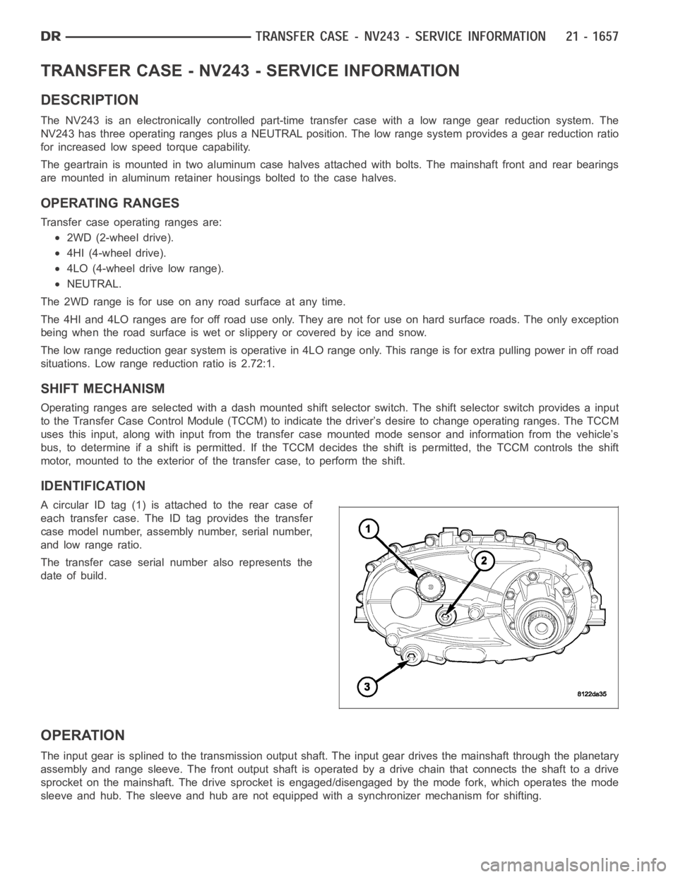
A circular ID tag (1) is attached to the rear case of
each transfer case. The ID tag provides the transfer
case model number, assembly number, serial number,
and low range ratio.
The transfer case serial number also represents the
date of build.
OPERATION
The input gear is splined to the transmission output shaft. The input gear drives the mainshaft through the planetary
assembly and range sleeve. The front output shaft is operated by a drive chain that connects the shaft to a drive
sprocket on the mainshaft. The drive sprocket is engaged/disengaged by themodefork,whichoperatesthemode
sleeve and hub. The sleeve and hub are not equipped with a synchronizer mechanism for shifting.
Page 4222 of 5267

TRANSFER CASE - NV244 GENII - SERVICE INFORMATION
DESCRIPTION
The NV244 GENII is an electronically controlled full and part-time transfer case with no two wheel drive operation.
A differential in the transfer case is used to control torque transfer to the front and rear axles. A low range gear
reduction system provides increased low speed torque capability for off road operation. The low range provides a
2.72:1 reduction ratio.
The geartrain is mounted in two aluminum case halves attached with bolts. The mainshaft front and rear bearings
are mounted in aluminum retainer housings bolted to the case halves.
OPERATING RANGES
NV244 GENII operating ranges are:
AWD (All-Wheel Drive).
4LOCK (Part-time).
4LO.
NEUTRAL.
The AWD mode can be used at any time and on any road surface.
The 4LOCK (Part-time) and 4LO ranges are for off road use only. The only timetheserangescanbeusediswhen
the road surface is covered with snow, ice, or other loose slippery material.
SHIFT MECHANISM
Operating ranges are selected with a dash mounted shift selector switch. The shift selector switch provides a input
to the Front Control Module (FCM) to indicate the driver’s desire to changeoperating ranges. The FCM uses this
input, along with the input from the transfer case mounted mode sensor and information from the vehicle’s bus, to
determine if a shift is permitted. If the FCM decides the shift is permitted, the FCM controls the shift motor, mounted
to the exterior of the transfer case, to perform the shift.
IDENTIFICATION
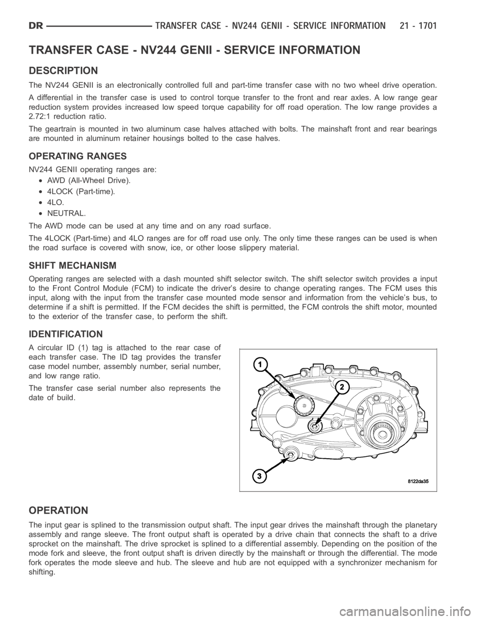
A circular ID (1) tag is attached to the rear case of
each transfer case. The ID tag provides the transfer
case model number, assembly number, serial number,
and low range ratio.
The transfer case serial number also represents the
date of build.
OPERATION
The input gear is splined to the transmission output shaft. The input gear drives the mainshaft through the planetary
assembly and range sleeve. The front output shaft is operated by a drive chain that connects the shaft to a drive
sprocket on the mainshaft. The drive sprocket is splined to a differentialassembly. Depending on the position of the
mode fork and sleeve, the front output shaft is driven directly by the mainshaft or through the differential. The mode
fork operates the mode sleeve and hub. The sleeve and hub are not equipped with a synchronizer mechanism for
shifting.
Page 4265 of 5267

TRANSFER CASE - NV273 - SERVICE INFORMATION
DESCRIPTION
The NV273 is an electronically controlled part-time transfer case with a low range gear reduction system. The
NV273 has three operating ranges plus a NEUTRAL position. The low range system provides a gear reduction ratio
for increased low speed torque capability.
The geartrain is mounted in two aluminum case halves attached with bolts. The mainshaft front and rear bearings
are mounted in aluminum case halves.
OPERATING RANGES
Transfer case operating ranges are:
2WD (2-wheel drive).
4HI (4-wheel drive).
4LO (4-wheel drive low range).
NEUTRAL.
The 2WD range is for use on any road surface at any time.
The 4HI and 4LO ranges are for off road use only. They are not for use on hard surface roads. The only exception
being when the road surface is wet or slippery or covered by ice and snow.
The low range reduction gear system is operative in 4LO range only. This range is for extra pulling power in off road
situations. Low range reduction ratio is 2.72:1.
SHIFT MECHANISM
Operating ranges are selected with a dash mounted shift selector switch. The shift selector switch provides a input
to the Transfer Case Control Module (TCCM) to indicate the driver’s desireto change operating ranges. The TCCM
uses this input, along with input from the transfer case mounted mode sensor and information from the vehicle’s
bus, to determine if a shift is permitted. If the TCCM decides the shift is permitted, the TCCM controls the shift
motor, mounted to the exterior of the transfer case, to perform the shift.
IDENTIFICATION
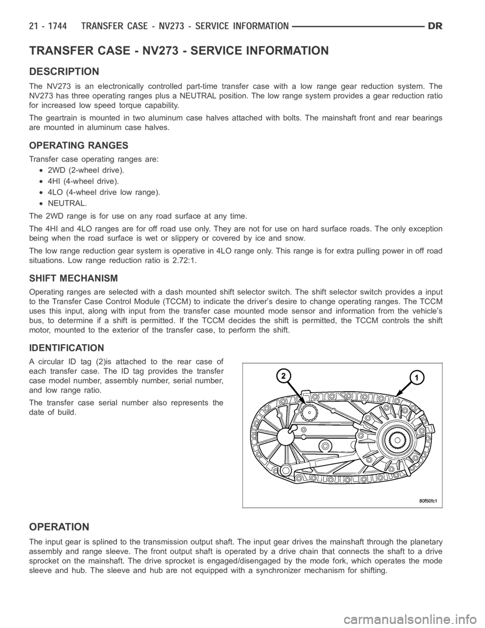
A circular ID tag (2)is attached to the rear case of
each transfer case. The ID tag provides the transfer
case model number, assembly number, serial number,
and low range ratio.
The transfer case serial number also represents the
date of build.
OPERATION
The input gear is splined to the transmission output shaft. The input gear drives the mainshaft through the planetary
assembly and range sleeve. The front output shaft is operated by a drive chain that connects the shaft to a drive
sprocket on the mainshaft. The drive sprocket is engaged/disengaged by themodefork,whichoperatesthemode
sleeve and hub. The sleeve and hub are not equipped with a synchronizer mechanism for shifting.