2006 DODGE RAM SRT-10 transmission oil
[x] Cancel search: transmission oilPage 998 of 5267

When Monitored:
With ECT greater than 147°F, after reaching a vehicle speed of 10 mph, and the throttle remaining open (off
idle) for 2 minutes, bring the vehicle to a stop and allow the engine to idle with the transmission in DRIVE.
Set Condition:
The oxygen sensor signal voltage is switching from below 0.27 of a volt to above 0.62 of a volt and back fewer
times than required.
Possible Causes
EXHAUST LEAK
(K41) O2 1/1 SIGNAL CIRCUIT
(K900) SENSOR GROUND CIRCUIT
O2 SENSOR
Always perform the Pre-Diagnostic Troubleshooting procedure before proceeding. (Refer to 9 - ENGINE -
DIAGNOSIS AND TESTING).
Diagnostic Test
1.ACTIVE DTC
NOTE: Check for contaminants that may have damaged the O2 Sensor: contaminated fuel, unapproved sil-
icone, oil and coolant.
Ignition on, engine not running.
NOTE: After the repairs have been made, verify proper O2 Sensor operation.If all the O2 Sensor voltage
readings have not returned to normal, follow the diagnostic procedure forthe remaining O2 Sensors.
With a scan tool, read DTCs.
Is the DTC active at this time?
Ye s>>
Go To 2
No>>
Refer to the INTERMITTENT CONDITION Symptom. (Refer to 9 - ENGINE - DIAGNOSIS AND TEST-
ING)
2.EXHAUST LEAK
Start the engine.
Inspect the exhaust system for leaks between the engine and the O2 Sensors.
Are there any exhaust leaks?
Ye s>>
Repair or replace the leaking exhaust parts as necessary.
Perform the POWERTRAIN VERIFICATION TEST. (Refer to 9 - ENGINE - STANDARD PROCEDURE)
No>>
Go To 3
3.(K41) O2 1/1 SIGNAL CIRCUIT VOLTAGE DROP
Turn the ignition off.
While backprobing, measure the voltage of the (K41) O2 Sensor 1/1 Signal circuit between the 1/1 O2 Sensor har-
ness connector and PCM harness connector.
NOTE: Make sure the voltmeter leads meet the terminals in the connector andthat there is good terminal to
wire connection and are connected for positive polarity.
Start the engine.
Page 1031 of 5267
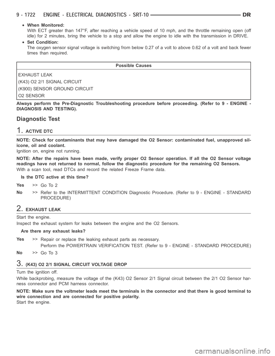
When Monitored:
With ECT greater than 147°F, after reaching a vehicle speed of 10 mph, and the throttle remaining open (off
idle) for 2 minutes, bring the vehicle to a stop and allow the engine to idle with the transmission in DRIVE.
Set Condition:
The oxygen sensor signal voltage is switching from below 0.27 of a volt to above 0.62 of a volt and back fewer
times than required.
Possible Causes
EXHAUST LEAK
(K43) O2 2/1 SIGNAL CIRCUIT
(K900) SENSOR GROUND CIRCUIT
O2 SENSOR
Always perform the Pre-Diagnostic Troubleshooting procedure before proceeding. (Refer to 9 - ENGINE -
DIAGNOSIS AND TESTING).
Diagnostic Test
1.ACTIVE DTC
NOTE: Check for contaminants that may have damaged the O2 Sensor: contaminated fuel, unapproved sil-
icone, oil and coolant.
Ignition on, engine not running.
NOTE: After the repairs have been made, verify proper O2 Sensor operation.If all the O2 Sensor voltage
readings have not returned to normal, follow the diagnostic procedure forthe remaining O2 Sensors.
With a scan tool, read DTCs and record the related Freeze Frame data.
Is the DTC active at this time?
Ye s>>
Go To 2
No>>
Refer to the INTERMITTENT CONDITION Diagnostic Procedure. (Refer to 9 - ENGINE - STANDARD
PROCEDURE)
2.EXHAUST LEAK
Start the engine.
Inspect the exhaust system for leaks between the engine and the O2 Sensors.
Are there any exhaust leaks?
Ye s>>
Repair or replace the leaking exhaust parts as necessary.
Perform the POWERTRAIN VERIFICATION TEST. (Refer to 9 - ENGINE - STANDARD PROCEDURE)
No>>
Go To 3
3.(K43) O2 2/1 SIGNAL CIRCUIT VOLTAGE DROP
Turn the ignition off.
While backprobing, measure the voltage of the (K43) O2 Sensor 2/1 Signal circuit between the 2/1 O2 Sensor har-
ness connector and PCM harness connector.
NOTE: Make sure the voltmeter leads meet the terminals in the connector andthat there is good terminal to
wire connection and are connected for positive polarity.
Start the engine.
Page 1495 of 5267
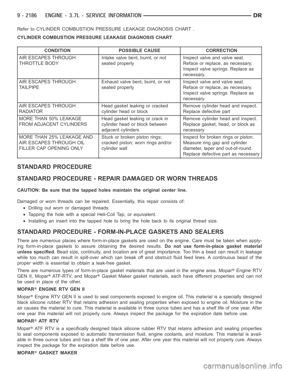
Refer to CYLINDER COMBUSTION PRESSURE LEAKAGE DIAGNOSIS CHART .
CYLINDER COMBUSTION PRESSURE LEAKAGE DIAGNOSIS CHART
CONDITION POSSIBLE CAUSE CORRECTION
AIR ESCAPES THROUGH
THROTTLE BODYIntake valve bent, burnt, or not
seated properlyInspect valve and valve seat.
Reface or replace, as necessary.
Inspect valve springs. Replace as
necessary.
AIR ESCAPES THROUGH
TAILPIPEExhaust valve bent, burnt, or not
seated properlyInspect valve and valve seat.
Reface or replace, as necessary.
Inspect valve springs. Replace as
necessary.
AIR ESCAPES THROUGH
RADIATORHead gasket leaking or cracked
cylinder head or blockRemove cylinder head and inspect.
Replace defective part
MORE THAN 50% LEAKAGE
FROM ADJACENT CYLINDERSHead gasket leaking or crack in
cylinder head or block between
adjacent cylindersRemove cylinder head and inspect.
Replace gasket, head, or block as
necessary
MORE THAN 25% LEAKAGE AND
AIR ESCAPES THROUGH OIL
FILLER CAP OPENING ONLYStuckorbrokenpistonrings;
cracked piston; worn rings and/or
cylinder wallInspect for broken rings or piston.
Measure ring gap and cylinder
diameter, taper and out-of-round.
Replace defective part as necessary
STANDARD PROCEDURE
STANDARD PROCEDURE - REPAIR DAMAGED OR WORN THREADS
CAUTION: Be sure that the tapped holes maintain the original center line.
Damaged or worn threads can be repaired. Essentially, this repair consistsof:
Drilling out worn or damaged threads.
Tapping the hole with a special Heli-Coil Tap, or equivalent.
Installing an insert into the tapped hole to bring the hole back to its original thread size.
STANDARD PROCEDURE - FORM-IN-PLACE GASKETS AND SEALERS
There are numerous places where form-in-place gaskets are used on the engine. Care must be taken when apply-
ing form-in-place gaskets to assure obtaining the desired results.Do not use form-in-place gasket material
unless specified.Bead size, continuity, and location are of great importance. Too thin a bead can result in leakage
while too much can result in spill-overwhich can break off and obstruct fluid feed lines. A continuous bead of the
proper width is essential to obtain a leak-free gasket.
There are numerous types of form-in-place gasket materials that are used in the engine area. Mopar
Engine RTV
GEN II, Mopar
ATF-RTV, and MoparGasket Maker gasket materials, each have different properties and can not
be used in place of the other.
MOPAR
ENGINE RTV GEN II
Mopar
Engine RTV GEN II is used to seal components exposed to engine oil. This material is a specially designed
black silicone rubber RTV that retains adhesion and sealing properties when exposed to engine oil. Moisture in the
air causes the material to cure. This material is available in three ounce tubes and has a shelf life of one year. After
one year this material will not properly cure. Always inspect the package for the expiration date before use.
MOPAR
AT F R T V
Mopar
ATF RTV is a specifically designed black silicone rubber RTV that retains adhesion and sealing properties
to seal components exposed to automatic transmission fluid, engine coolants, and moisture. This material is avail-
able in three ounce tubes and has a shelf life of one year. After one year thismaterial will not properly cure. Always
inspect the package for the expiration date before use.
MOPAR
GASKET MAKER
Page 1509 of 5267
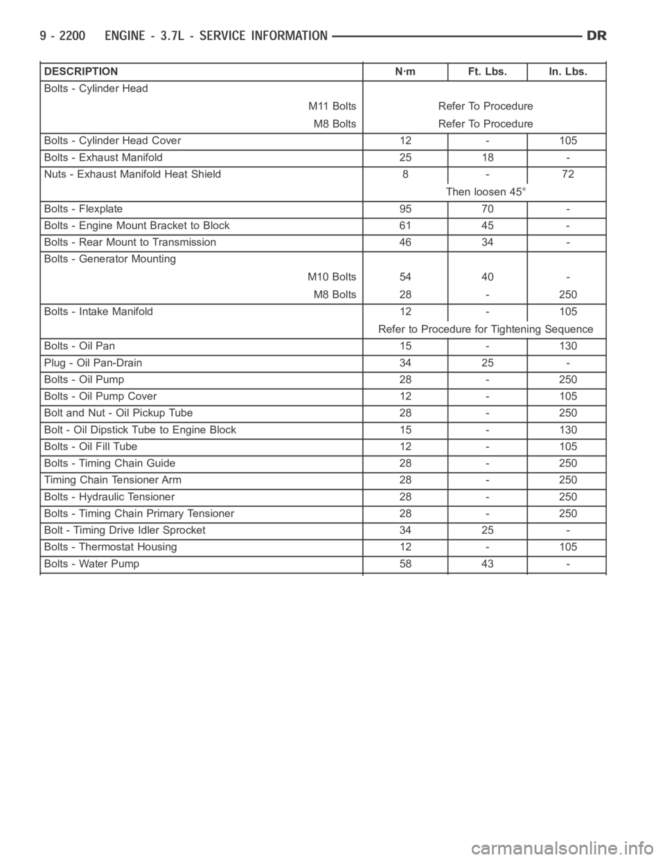
DESCRIPTION Nꞏm Ft. Lbs. In. Lbs.
Bolts - Cylinder Head
M11 Bolts Refer To Procedure
M8 Bolts Refer To Procedure
Bolts - Cylinder Head Cover 12 - 105
Bolts - Exhaust Manifold 25 18 -
Nuts - Exhaust Manifold Heat Shield 8 - 72
Then loosen 45°
Bolts - Flexplate 95 70 -
Bolts - Engine Mount Bracket to Block 61 45 -
Bolts - Rear Mount to Transmission 46 34 -
Bolts - Generator Mounting
M10 Bolts 54 40 -
M8 Bolts 28 - 250
Bolts - Intake Manifold 12 - 105
Refer to Procedure for Tightening Sequence
Bolts - Oil Pan 15 - 130
Plug - Oil Pan-Drain 34 25 -
Bolts - Oil Pump 28 - 250
Bolts - Oil Pump Cover 12 - 105
Bolt and Nut - Oil Pickup Tube 28 - 250
Bolt - Oil Dipstick Tube to Engine Block 15 - 130
Bolts - Oil Fill Tube 12 - 105
Bolts - Timing Chain Guide 28 - 250
Timing Chain Tensioner Arm 28 - 250
Bolts - Hydraulic Tensioner 28 - 250
Bolts - Timing Chain Primary Tensioner 28 - 250
Bolt - Timing Drive Idler Sprocket 34 25 -
Bolts - Thermostat Housing 12 - 105
Bolts - Water Pump 58 43 -
Page 1553 of 5267
BLOCK-ENGINE
DESCRIPTION
The cylinder block is made of cast iron.The block is a closed deck design with the left bank forward. To provide
high rigidity and improved NVH an enhanced compacted graphite bedplate isbolted to the block. The block design
allows coolant flow between the cylinders bores, and an internal coolant bypass to a single poppet inlet thermostat
is included in the cast aluminum front cover.
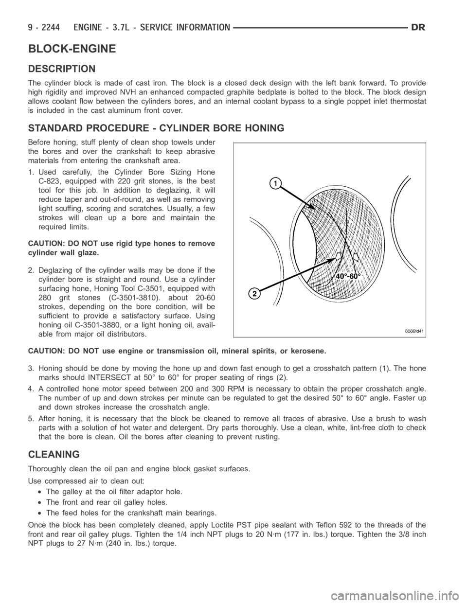
STANDARD PROCEDURE - CYLINDER BORE HONING
Before honing, stuff plenty of clean shop towels under
the bores and over the crankshaft to keep abrasive
materials from entering the crankshaft area.
1. Used carefully, the Cylinder Bore Sizing Hone
C-823, equipped with 220 grit stones, is the best
tool for this job. In addition to deglazing, it will
reduce taper and out-of-round, as well as removing
light scuffing, scoring and scratches. Usually, a few
strokes will clean up a bore and maintain the
required limits.
CAUTION: DO NOT use rigid type hones to remove
cylinder wall glaze.
2. Deglazing of the cylinder walls may be done if the
cylinder bore is straight and round. Use a cylinder
surfacing hone, Honing Tool C-3501, equipped with
280 grit stones (C-3501-3810). about 20-60
strokes, depending on the bore condition, will be
sufficient to provide a satisfactory surface. Using
honing oil C-3501-3880, or a light honing oil, avail-
able from major oil distributors.
CAUTION: DO NOT use engine or transmission oil, mineral spirits, or kerosene.
3. Honing should be done by moving the hone up and down fast enough to get a crosshatch pattern (1). The hone
marks should INTERSECT at 50° to 60° for proper seating of rings (2).
4. A controlled hone motor speed between 200 and 300 RPM is necessary to obtain the proper crosshatch angle.
The number of up and down strokes per minute can be regulated to get the desired 50° to 60° angle. Faster up
and down strokes increase the crosshatch angle.
5. After honing, it is necessary that the block be cleaned to remove all traces of abrasive. Use a brush to wash
parts with a solution of hot water and detergent. Dry parts thoroughly. Usea clean, white, lint-free cloth to check
that the bore is clean. Oil the bores after cleaning to prevent rusting.
CLEANING
Thoroughly clean the oil pan and engine block gasket surfaces.
Use compressed air to clean out:
The galley at the oil filter adaptor hole.
The front and rear oil galley holes.
The feed holes for the crankshaft main bearings.
Once the block has been completely cleaned, apply Loctite PST pipe sealantwith Teflon 592 to the threads of the
front and rear oil galley plugs. Tighten the 1/4 inch NPT plugs to 20 Nꞏm (177in. lbs.) torque. Tighten the 3/8 inch
NPT plugs to 27 Nꞏm (240 in. lbs.) torque.
Page 1562 of 5267
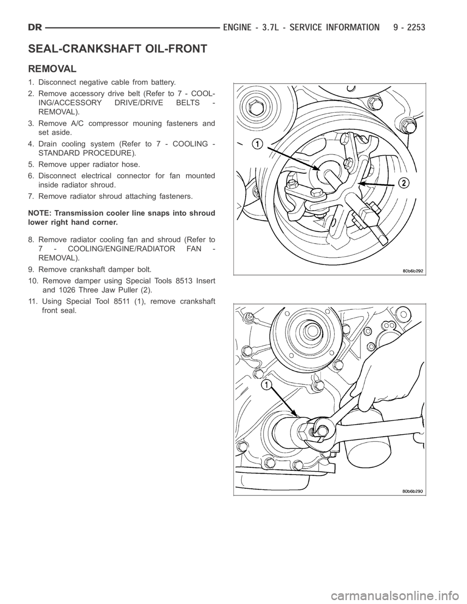
SEAL-CRANKSHAFT OIL-FRONT
REMOVAL
1. Disconnect negative cable from battery.
2. Remove accessory drive belt (Refer to 7 - COOL-
ING/ACCESSORY DRIVE/DRIVE BELTS -
REMOVAL).
3. Remove A/C compressor mouning fasteners and
set aside.
4. Drain cooling system (Refer to 7 - COOLING -
STANDARD PROCEDURE).
5. Remove upper radiator hose.
6. Disconnect electrical connector for fan mounted
inside radiator shroud.
7. Remove radiator shroud attaching fasteners.
NOTE: Transmission cooler line snaps into shroud
lower right hand corner.
8. Remove radiator cooling fan and shroud (Refer to
7 - COOLING/ENGINE/RADIATOR FAN -
REMOVAL).
9. Remove crankshaft damper bolt.
10. Remove damper using Special Tools 8513 Insert
and 1026 Three Jaw Puller (2).
11. Using Special Tool 8511 (1), remove crankshaft
front seal.
Page 1565 of 5267
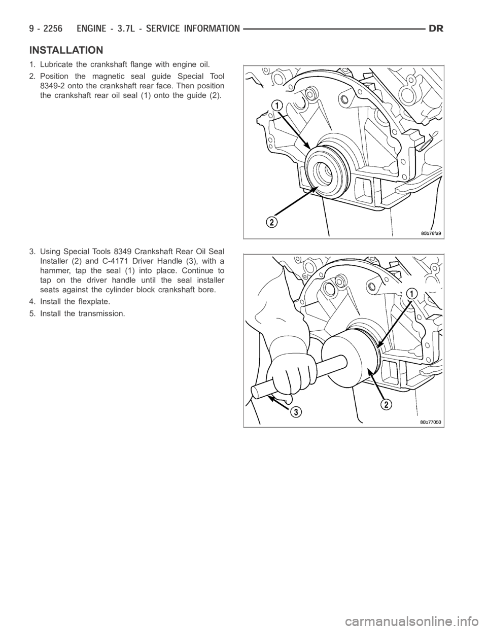
INSTALLATION
1. Lubricate the crankshaft flange with engine oil.
2. Position the magnetic seal guide Special Tool
8349-2 onto the crankshaft rear face. Then position
the crankshaft rear oil seal (1) onto the guide (2).
3. Using Special Tools 8349 Crankshaft Rear Oil Seal
Installer (2) and C-4171 Driver Handle (3), with a
hammer, tap the seal (1) into place. Continue to
tap on the driver handle until the seal installer
seats against the cylinder block crankshaft bore.
4. Install the flexplate.
5. Install the transmission.
Page 1629 of 5267
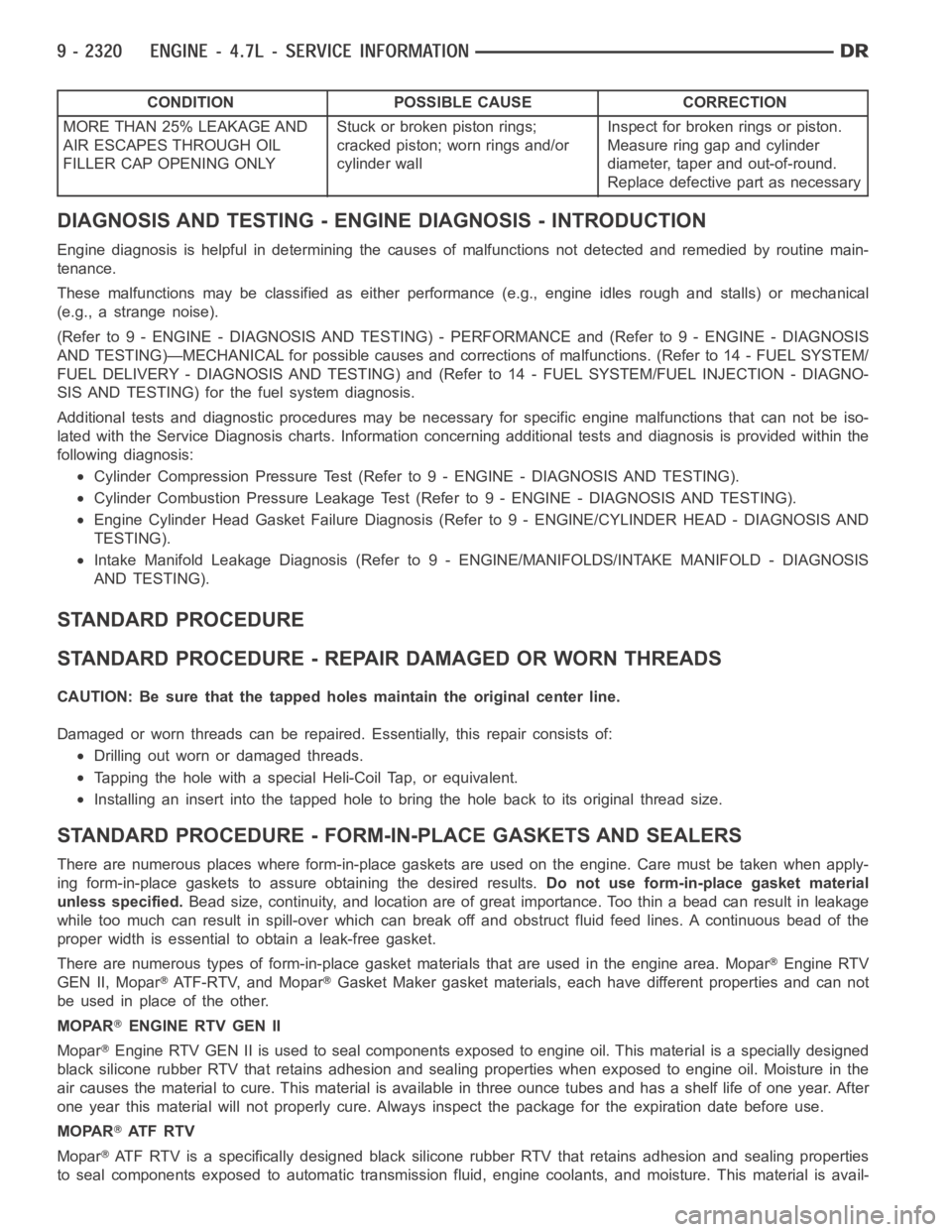
CONDITION POSSIBLE CAUSE CORRECTION
MORE THAN 25% LEAKAGE AND
AIR ESCAPES THROUGH OIL
FILLER CAP OPENING ONLYStuckorbrokenpistonrings;
cracked piston; worn rings and/or
cylinder wallInspect for broken rings or piston.
Measure ring gap and cylinder
diameter, taper and out-of-round.
Replace defective part as necessary
DIAGNOSIS AND TESTING - ENGINE DIAGNOSIS - INTRODUCTION
Engine diagnosis is helpful in determining the causes of malfunctions notdetected and remedied by routine main-
tenance.
These malfunctions may be classified as either performance (e.g., engineidles rough and stalls) or mechanical
(e.g., a strange noise).
(Refer to 9 - ENGINE - DIAGNOSIS AND TESTING) - PERFORMANCE and (Refer to 9 - ENGINE - DIAGNOSIS
AND TESTING)—MECHANICAL for possible causes and corrections of malfunctions. (Refer to 14 - FUEL SYSTEM/
FUEL DELIVERY - DIAGNOSIS AND TESTING) and (Refer to 14 - FUEL SYSTEM/FUEL INJECTION - DIAGNO-
SIS AND TESTING) for the fuel system diagnosis.
Additional tests and diagnostic procedures may be necessary for specificengine malfunctions that can not be iso-
lated with the Service Diagnosis charts. Information concerning additional tests and diagnosis is provided within the
following diagnosis:
Cylinder Compression Pressure Test (Refer to 9 - ENGINE - DIAGNOSIS AND TESTING).
Cylinder Combustion Pressure LeakageTest (Refer to 9 - ENGINE - DIAGNOSISAND TESTING).
Engine Cylinder Head Gasket Failure Diagnosis (Refer to 9 - ENGINE/CYLINDER HEAD - DIAGNOSIS AND
TESTING).
Intake Manifold Leakage Diagnosis (Refer to 9 - ENGINE/MANIFOLDS/INTAKEMANIFOLD - DIAGNOSIS
AND TESTING).
STANDARD PROCEDURE
STANDARD PROCEDURE - REPAIR DAMAGED OR WORN THREADS
CAUTION: Be sure that the tapped holes maintain the original center line.
Damaged or worn threads can be repaired. Essentially, this repair consistsof:
Drilling out worn or damaged threads.
Tapping the hole with a special Heli-Coil Tap, or equivalent.
Installing an insert into the tapped hole to bring the hole back to its original thread size.
STANDARD PROCEDURE - FORM-IN-PLACE GASKETS AND SEALERS
There are numerous places where form-in-place gaskets are used on the engine. Care must be taken when apply-
ing form-in-place gaskets to assure obtaining the desired results.Do not use form-in-place gasket material
unless specified.Bead size, continuity, and location are of great importance. Too thin a bead can result in leakage
while too much can result in spill-overwhich can break off and obstruct fluid feed lines. A continuous bead of the
proper width is essential to obtain a leak-free gasket.
There are numerous types of form-in-place gasket materials that are used in the engine area. Mopar
Engine RTV
GEN II, Mopar
ATF-RTV, and MoparGasket Maker gasket materials, each have different properties and can not
be used in place of the other.
MOPAR
ENGINE RTV GEN II
Mopar
Engine RTV GEN II is used to seal components exposed to engine oil. This material is a specially designed
black silicone rubber RTV that retains adhesion and sealing properties when exposed to engine oil. Moisture in the
air causes the material to cure. This material is available in three ounce tubes and has a shelf life of one year. After
one year this material will not properly cure. Always inspect the package for the expiration date before use.
MOPAR
AT F R T V
Mopar
ATF RTV is a specifically designed black silicone rubber RTV that retains adhesion and sealing properties
to seal components exposed to automatic transmission fluid, engine coolants, and moisture. This material is avail-