Page 1776 of 5267
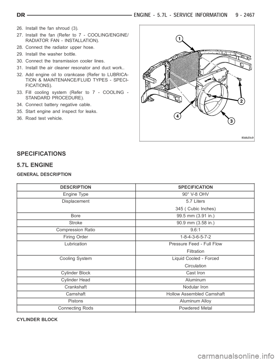
26. Install the fan shroud (3).
27. Install the fan (Refer to 7 - COOLING/ENGINE/
RADIATOR FAN - INSTALLATION).
28. Connect the radiator upper hose.
29. Install the washer bottle.
30. Connect the transmission cooler lines.
31. Install the air cleaner resonator and duct work..
32. Add engine oil to crankcase (Refer to LUBRICA-
TION & MAINTENANCE/FLUID TYPES - SPECI-
FICATIONS).
33. Fill cooling system (Refer to 7 - COOLING -
STANDARD PROCEDURE).
34. Connect battery negative cable.
35. Start engine and inspect for leaks.
36. Road test vehicle.
SPECIFICATIONS
5.7L ENGINE
GENERAL DESCRIPTION
DESCRIPTION SPECIFICATION
Engine Type 90° V-8 OHV
Displacement 5.7 Liters
345 ( Cubic Inches)
Bore 99.5 mm (3.91 in.)
Stroke 90.9 mm (3.58 in.)
Compression Ratio 9.6:1
Firing Order 1-8-4-3-6-5-7-2
Lubrication Pressure Feed - Full Flow
Filtration
Cooling System Liquid Cooled - Forced
Circulation
Cylinder Block Cast Iron
Cylinder Head Aluminum
Crankshaft Nodular Iron
Camshaft Hollow Assembled Camshaft
Pistons Aluminum Alloy
Connecting Rods Powdered Metal
CYLINDER BLOCK
Page 1782 of 5267
DESCRIPTION Nꞏm Ft. In.
Oil Pan—Drain Plug 34 25 —
Oil Pump—Attaching Bolts 28 — 250
Oil Pump Pickup Tube – Bolt and Nut 28 — 250
Rear Seal Retainer Attaching Bolts 15 — 132
Rear Insulator to Bracket— 68 50 —
Through-Bolt (2WD)
Rear Insulator to Crossmember 41 30 —
Support Bracket—Nut (2WD)
Rear Insulator to Crossmember— 68 50 —
Nuts (4WD)
Rear Insulator to Transmission— 68 50 —
Bolts (4WD)
Rear Insulator Bracket—Bolts 68 50 —
(4WD Automatic)
Rear Support Bracket to 41 30 —
Crossmember Flange—Nuts
Rear Support Plate to Transfer 41 30 —
Case—Bolts
Rocker Arm—Bolts 22 — 195
Spark Plugs — — —
Thermostat Housing—Bolts 28 — 250
Throttle Body—Bolts 12 — 105
Transfer Case to Insulator 204 105 —
Mounting Plate—Nuts
Transmission Support Bracket— 68 50 —
Bolts (2WD)
Vibration Damper—Bolt 176 129 —
Water Pump to Timing Chain 28 — 250
Case Cover—Bolts
Page 1849 of 5267
3. Using Special Tool 8506 (1), remove the crankshaft rear oil seal (2).
INSTALLATION
CAUTION: The rear seal must be installed dry for
proper operation. Do not lubricate the seal lip or
outer edge.
1. Position the plastic seal guide (2) onto the crank-
shaft rear face. Then position the crankshaft rear
oil seal (3) onto the guide.
2. Using Special Tools 8349 Crankshaft Rear Oil Seal
Installer (1) and C-4171 Driver Handle, with a ham-
mer, tap the seal (3) into place. Continue to tap on
the driver handle until the seal installer seats
against the cylinder block crankshaft bore.
3. Install the flexplate. (Refer to 9 - ENGINE/ENGINE
BLOCK/FLEX PLATE - INSTALLATION).
4. Install the transmission.
Page 1850 of 5267
RETAINER - CRANK REAR OIL - SEAL
REMOVAL
1. Disconnect negative cable from battery.
2. Remove the transmission. (Refer to 21 - TRANS-
MISSION/TRANSAXLE/AUTOMATIC - NAG1 -
REMOVAL).
3. Remove the flexplate. (Refer to 9 - ENGINE/EN-
GINE BLOCK/FLEX PLATE - REMOVAL).
4. Remove the oil pan. (Refer to 9 - ENGINE/LUBRI-
CATION/OIL PAN - REMOVAL)
5. Remove the rear oil seal retainer mounting bolts.
6. Carefully remove the retainer from the engine
block.
INSTALLATION
1. Throughly clean all gasket resdue from the engine
block.
2. Use extream care and clean all gasket resdue from
the retainer.
3. Position the gasket onto the retainer.
4. Position the retainer onto the engine block.
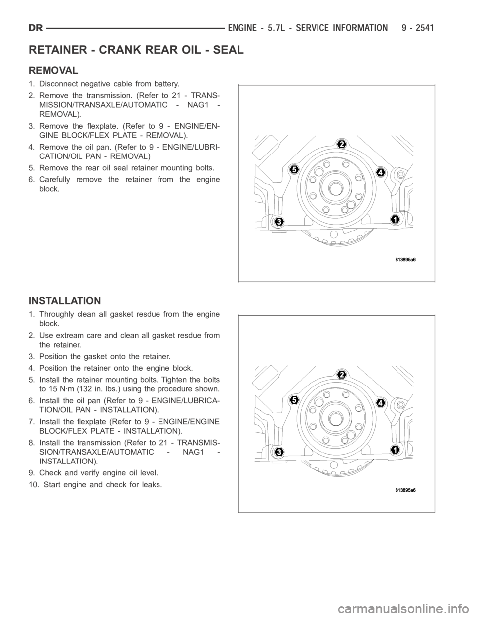
5. Install the retainer mounting bolts. Tighten the bolts
to 15 Nꞏm (132 in. lbs.) using the procedure shown.
6. Install the oil pan (Refer to 9 - ENGINE/LUBRICA-
TION/OIL PAN - INSTALLATION).
7. Install the flexplate (Refer to 9 - ENGINE/ENGINE
BLOCK/FLEX PLATE - INSTALLATION).
8. Install the transmission (Refer to 21 - TRANSMIS-
SION/TRANSAXLE/AUTOMATIC - NAG1 -
INSTALLATION).
9. Check and verify engine oil level.
10. Start engine and check for leaks.
Page 1879 of 5267
PA N - E N G I N E O I L
REMOVAL
1. Disconnect the negative battery cable.
2. Install engine support fixture special tool # 8534.Do not raise engine at this time.
3.For 2WD vehicles,Remove both engine mount to frame through bolts.
4.For 4WD vehicles,Loosen both left and right side engine mount bracket to mount bolts, and remove the lower
bolt on each side. The upper hole in the engine bracket is slotted.
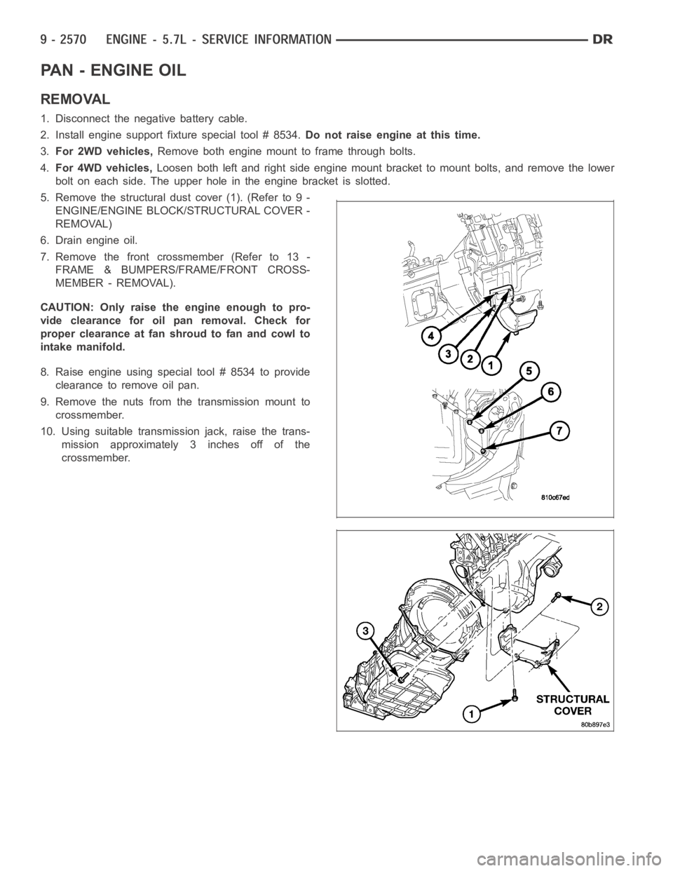
5. Remove the structural dust cover (1). (Refer to 9 -
ENGINE/ENGINE BLOCK/STRUCTURAL COVER -
REMOVAL)
6. Drain engine oil.
7. Remove the front crossmember (Refer to 13 -
FRAME & BUMPERS/FRAME/FRONT CROSS-
MEMBER - REMOVAL).
CAUTION: Only raise the engine enough to pro-
vide clearance for oil pan removal. Check for
proper clearance at fan shroud to fan and cowl to
intake manifold.
8. Raise engine using special tool # 8534 to provide
clearance to remove oil pan.
9. Remove the nuts from the transmission mount to
crossmember.
10. Using suitable transmission jack, raise the trans-
mission approximately 3 inches off of the
crossmember.
Page 1881 of 5267
2. Apply MoparEngine RTV at the 4 T- joints.
NOTE: When the oil pan is removed, a new inte-
gral windage tray and gasket assembly must be
installed. The old gasket cannot be reused.
3. Install a new integral windage tray and gasket.
4. Reinstall the oil pump pickup tube with new o-ring.
Tighten tube to pump fasteners to 28 Nꞏm (250 in.
lbs.).
NOTE: The double ended oil pan studs must be
installed in the same location that they were
removed from.
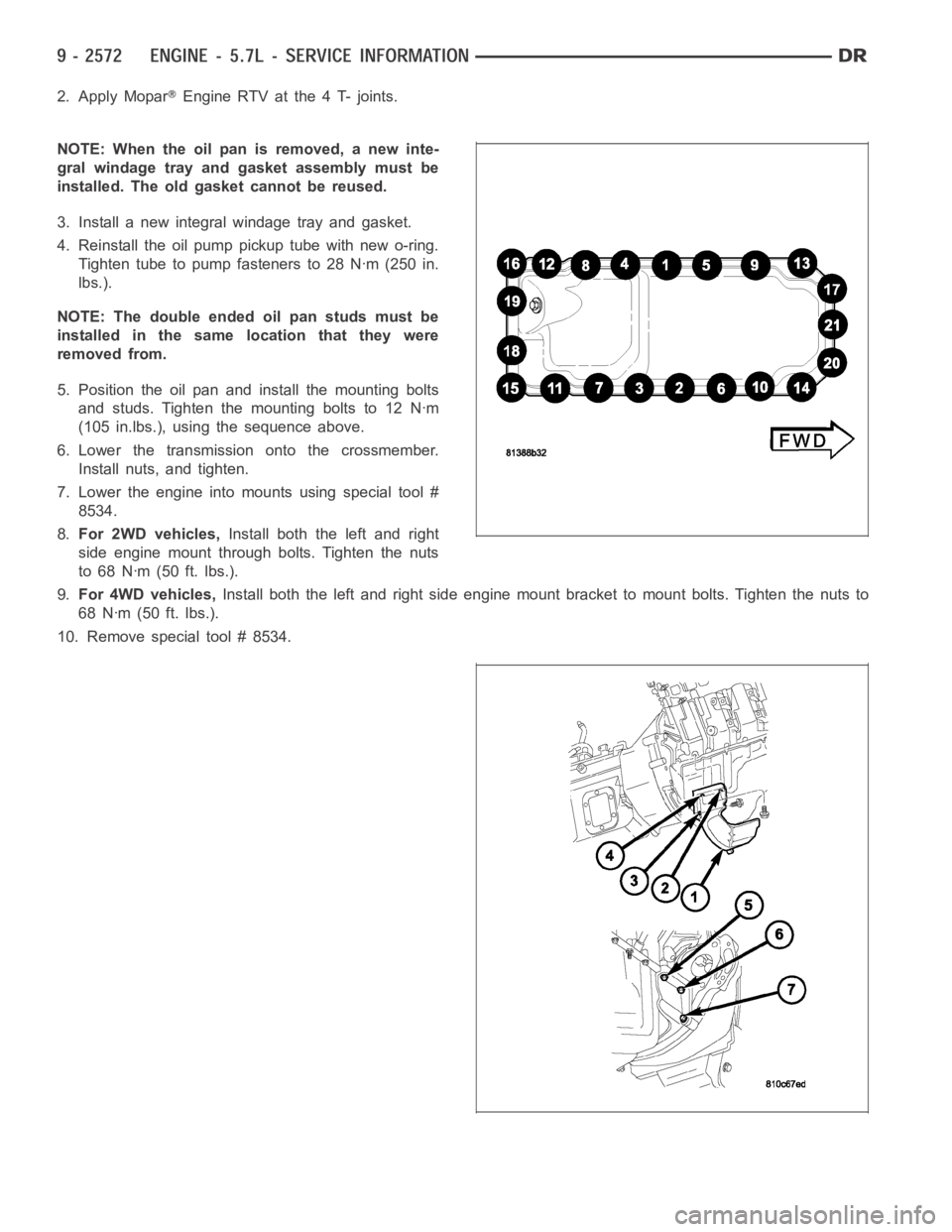
5. Position the oil pan and install the mounting bolts
and studs. Tighten the mounting bolts to 12 Nꞏm
(105 in.lbs.), using the sequence above.
6. Lower the transmission onto the crossmember.
Install nuts, and tighten.
7. Lower the engine into mounts using special tool #
8534.
8.For 2WD vehicles,Install both the left and right
side engine mount through bolts. Tighten the nuts
to 68 Nꞏm (50 ft. lbs.).
9.For 4WD vehicles,Install both the left and right side engine mount bracket to mount bolts. Tighten the nuts to
68 Nꞏm (50 ft. lbs.).
10. Remove special tool # 8534.
Page 1913 of 5267
MoparEngine RTV GEN II is used to seal components exposed to engine oil. This material is a specially designed
black silicone rubber RTV that retains adhesion and sealing properties when exposed to engine oil. Moisture in the
air causes the material to cure. This material is available in three ounce tubes and has a shelf life of one year. After
one year this material will not properly cure. Always inspect the package for the expiration date before use.
MOPAR
AT F R T V
Mopar
ATF RTV is a specifically designed black silicone rubber RTV that retains adhesion and sealing properties
to seal components exposed to automatic transmission fluid, engine coolants, and moisture. This material is avail-
able in three ounce tubes and has a shelf life of one year. After one year thismaterial will not properly cure. Always
inspect the package for the expiration date before use.
MOPAR
GASKET MAKER
Mopar
Gasket Maker is an anaerobic type gasket material. The material cures in the absence of air when
squeezed between two metallic surfaces. It will not cure if left in the uncovered tube. The anaerobic material is for
use between two machined surfaces. Do not use on flexible metal flanges.
MOPAR
GASKET SEALANT
Mopar
Gasket Sealant is a slow drying, permanently soft sealer. This material isrecommended for sealing
threaded fittings and gaskets against leakage of oil and coolant. Can be used on threaded and machined parts
under all temperatures. This material is used on engines with multi-layersteel (MLS) cylinder head gaskets. This
material also will prevent corrosion. Mopar
Gasket Sealant is available in a 13 oz. aerosol can or 4oz./16 oz. can
w/applicator.
FORM-IN-PLACE GASKET AND SEALER APPLICATION
Assembling parts using a form-in-place gasket requires care but it’s easier than using precut gaskets.
Mopar
Gasket Maker material should be applied sparingly 1 mm (0.040 in.) diameter or less of sealant to one
gasket surface. Be certain the material surrounds each mounting hole. Excess material can easily be wiped off.
Components should be torqued in place within 15 minutes. The use of a locating dowel is recommended during
assembly to prevent smearing material off the location.
Mopar
Engine RTV GEN II or ATF RTV gasket material should be applied in a continuous bead approximately 3
mm (0.120 in.) in diameter. All mounting holes must be circled. For corner sealing, a 3.17 or 6.35 mm (1/8 or 1/4 in.)
drop is placed in the center of the gasket contact area. Uncured sealant maybe removed with a shop towel. Com-
ponents should be torqued in place while the sealant is still wet to the touch (within 10 minutes). The usage of a
locating dowel is recommended during assembly to prevent smearing material off the location.
Mopar
Gasket Sealant in an aerosol can should be applied using a thin, even coat sprayed completely over both
surfaces to be joined, and both sides of a gasket. Then proceed with assembly. Material in a can w/applicator can
be brushed on evenly over the sealing surfaces. Material in an aerosol can shouldbeusedonengineswithmulti-
layer steel gaskets.
STANDARD PROCEDURE - REPAIR DAMAGED OR WORN THREADS
CAUTION: Be sure that the tapped holes maintain the original center line.
Damaged or worn threads can be repaired. Essentially, this repair consistsof:
Drilling out worn or damaged threads.
Tapping the hole with a special Heli-Coil Tap, or equivalent.
Installing an insert into the tapped hole to bring the hole back to its original thread size.
STANDARD PROCEDURE—HYDROSTATIC LOCK
CAUTION: DO NOT use the starter motor to rotate the crankshaft. Severe damage could occur.
When an engine is suspected of hydrostatic lock (regardless of what causedthe problem), follow the steps below.
1. Disconnect the negative cable(s) from the battery.
2. Inspect air cleaner, induction system, and intake manifold to ensure system is dry and clear of foreign material.
Page 1915 of 5267
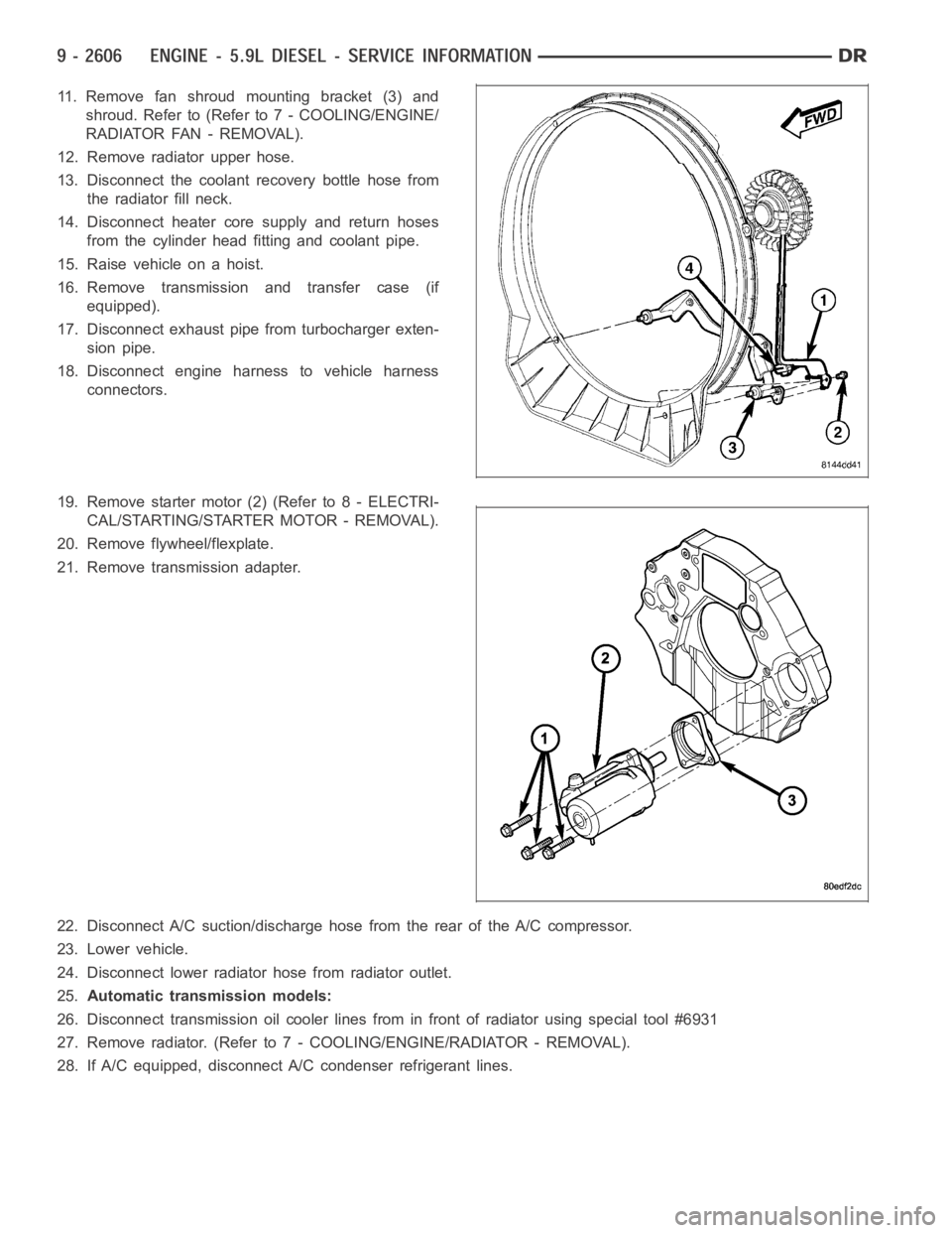
11. Remove fan shroud mounting bracket (3) and
shroud. Refer to (Refer to 7 - COOLING/ENGINE/
RADIATOR FAN - REMOVAL).
12. Remove radiator upper hose.
13. Disconnect the coolant recovery bottle hose from
the radiator fill neck.
14. Disconnect heater core supply and return hoses
from the cylinder head fitting and coolant pipe.
15. Raise vehicle on a hoist.
16. Remove transmission and transfer case (if
equipped).
17. Disconnect exhaust pipe from turbocharger exten-
sion pipe.
18. Disconnect engine harness to vehicle harness
connectors.
19. Remove starter motor (2) (Refer to 8 - ELECTRI-
CAL/STARTING/STARTER MOTOR - REMOVAL).
20. Remove flywheel/flexplate.
21. Remove transmission adapter.
22. Disconnect A/C suction/discharge hose from the rear of the A/C compressor.
23. Lower vehicle.
24. Disconnect lower radiator hose from radiator outlet.
25.Automatic transmission models:
26. Disconnect transmission oil cooler lines from in front of radiator using special tool #6931
27. Remove radiator. (Refer to 7 - COOLING/ENGINE/RADIATOR - REMOVAL).
28. If A/C equipped, disconnect A/C condenser refrigerant lines.