2006 DODGE RAM SRT-10 ESP inoperative
[x] Cancel search: ESP inoperativePage 2923 of 5267

5. Iftheunderdriveclutchpressureisgreaterthan5psiinStep4ofTestTwo-A, a defective solenoid/pressure
switch assembly or controller is the cause.
ALL PRESSURE SPECIFICATIONS ARE PSI (on hoist, with wheels free to turn)
Gear Selector Position Actual Gear PRESSURE TAPS
Under-
drive
ClutchOver-
drive
ClutchReverse
ClutchTo r q u e
Converter
Clutch
OffTo r q u e
Converter
Clutch
On2/4
ClutchLow/
Reverse
Clutch
PARK - 0 mph * PARK 0-2 0-5 0-2 60-110 45-100 0-2 115-145
REVERSE - 0 mph * REVERSE 0-2 0-7 165-235 50-100 35-85 0-2 165-235
NEUTRAL - 0 mph * NEUTRAL 0-2 0-5 0-2 60-110 45-100 0-2 115-145
Low - 20 mph # FIRST 110-
1450-5 0-2 60-110 45-100 0-2 115-145
Third-30mph# SECOND 110-
1450-5 0-2 60-110 45-100 115-
1450-2
Third - 45 mph # DIRECT 75-95 75-95 0-2 60-90 45-80 0-2 0-2
OD - 30 mph # OVERDRIVE 0-2 75-95 0-2 60-90 45-80 75-95 0-2
OD - 50 mph # OVERDRIVE WITH
TCC0-2 75-95 0-2 0-5 60-95 75-95 0-2
* Engine Speed at 1500 rpm
# CAUTION: Both wheels must be turning at same speed.
CLUTCH AIR PRESSURE TESTS
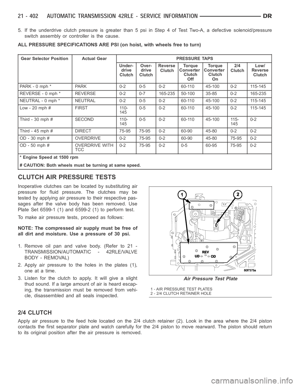
Inoperative clutches can be located by substituting air
pressure for fluid pressure. The clutches may be
tested by applying air pressure to their respective pas-
sages after the valve body has been removed. Use
Plate Set 6599-1 (1) and 6599-2 (1) to perform test.
To make air pressure tests, proceed as follows:
NOTE: The compressed air supply must be free of
all dirt and moisture. Use a pressure of 30 psi.
1. Remove oil pan and valve body. (Refer to 21 -
TRANSMISSION/AUTOMATIC - 42RLE/VALVE
BODY - REMOVAL)
2. Apply air pressure to the holes in the plates (1),
one at a time.
3. Listen for the clutch to apply. It will give a slight
thud sound. If a large amount of air is heard escap-
ing, the transmission must be removed from vehi-
cle, disassembled and all seals inspected.
2/4 CLUTCH
Apply air pressure to the feed hole located on the 2/4 clutch retainer (2). Look in the area where the 2/4 piston
contacts the first separator plate and watch carefully for the 2/4 piston tomoverearward.Thepistonshouldreturn
to its original position after the air pressure is removed.
Air Pressure Test Plate
1 - AIR PRESSURE TEST PLATES
2 - 2/4 CLUTCH RETAINER HOLE
Page 4610 of 5267

The motor/module is programmed to learn the speed required to drive the panel based on position and recalibrates
itself as needed. If the sunroof becomes uncalibrated, it will only respond to the vent switch. If the vent switch is
pressed, the glass will move toward vent; if the switch is released, all motion stops. In the event that the sunroof
system becomes uncalibrated performthe sunroof position calibration procedure, (Refer to 8 - ELECTRICAL/
POWER TOP/MOTOR - STANDARD PROCEDURE -SUNROOF POSITION CALIBRATION).
DIAGNOSIS AND TESTING
POWER TOP - SUNROOF
Any diagnosis of the power sunroof system should begin with the use of a scantool and the proper Diagnostic
Procedures Information. The scan tool can provide confirmation that the Controller Area Network (CAN) Data Bus is
functional, that all of the electronic modules are sending and receiving the proper messages on the CAN Data Bus,
and that the power sunroof motor is being sent the proper hard wired output by the sunroof switch.
For complete circuit diagrams, refer to the appropriate wiring information. The wiring information includes wiring dia-
grams, proper wire and connector repair procedures, details of wire harness routing and retention, connector pin-out
information and location views for the various wire harness connectors, splices and grounds.
Refer to the appropriate diagnostic information.
SUNROOF
Refer to SUNROOF DIAGNOSIS CHART for possible causes. Before beginning sunroof diagnostics verify that all
other power accessories are in proper operating condition. If not, a common electrical problem may exist. Refer to
Wiring Diagrams, in this publication for circuit, splice and component descriptions. Check the condition of the circuit
protection (20 amp circuit breaker in the Junction Block). Inspect all wiring connector pins for proper engagement
and continuity. Check for battery voltage at the power sunroof controller, refer to Wiring Diagrams, for circuit infor-
mation. If battery voltage of more than 10 volts is detected at the controller, proceed with the following tests (the
controller will not operate at less than 10 volts).
Before beginning diagnosis for wind noise or water leaks, verify that the problem was not caused by releasing the
control switch before the sunroof was fully closed. The sunroof module hasa water-management system. If how-
ever, the sunroof glass is in a partial closed position, high pressure water may be forced beyond the water man-
agement system boundariesand onto the headlining.
Every time the sunroof module loses power it must be initialized. This is done by connecting power to the sunroof
and moving the sunroof toward the closed position. When initialization occurs a slight “kick” in the sunroof module
will be seen and heard. This is the indication that the sunroof module is initialized
SUNROOF DIAGNOSIS CHART
SYMPTOM POSSIBLE CAUSE
Sunroof motor inoperative. Faulty control switch.
Faulty circuit ground between sunroof module, control switch,
and body harness.
Faulty power circuit between sunroof module, control switch,
and body harness.
Faulty sunroof drive motor.
Faulty sunroof module.
Audible whine when switch is depressed,
sunroof does not operate.Faulty sunroof drive motor.
Binding cable.
Audible clicking or ratcheting when switch is
pressed, sunroof does not operate.Broken or worn drive cable.
Worn drive motor gear.
Mechanisms not synchronized.
Page 5046 of 5267

*HVAC SYSTEM TEST
For a complete wiring diagramRefer to Section 8W.
Theory of Operation
The HVAC System Test provides a starting point in the diagnostic process byidentifying the appropriate diagnostic
procedure or system test to perform when diagnosing a given symptom, condition, or DTC. It also provides a means
for testing the entire HVAC system byutilizing the A/C-heater control’s On-Board System Tests. The On-Board Sys-
tem Tests can also assist in diagnosing stored DTCs. (Refer to 24 - HEATING &AIR CONDITIONING - DIAGNOSIS
AND TESTING) for additional information about on-board diagnostics.
Diagnostic Test
1.HVAC SYSTEM TEST
NOTE: Diagnose and repair all active DTCs before diagnosing and repairingstored DTCs.
Make a selection based on the symptom, condition, or DTC that you want to diagnose.
For Any Active DTC
Refer to the Table of Contents in this Section for a complete list of HVAC related symptoms.
Scan Tool Indicates HVAC Not Active On Bus
(Refer to 8 - ELECTRICAL/ELECTRONIC CONTROL MODULES - DIAGNOSIS AND TESTING) for no
response related diagnostic procedures.
Blower Motor Inoperative
Refer to *Blower Motor Inoperative in this Section.
Complete HVAC System Test
Go To 2
A/C System Performance Test
Go To 2
Mode Switch & Door Actuator Ckt Test
Go To 3
Actuator DTC Detection Test
Go To 4
Actuator Calibration Test
Go To 5
2.A/C SYSTEM PERFORMANCE TEST
NOTE: The following are prerequisites of the Cooldown Test. Verify each ofthe following before running the
test:
If active, diagnose and repair Evaporator Temperature Sensor related DTCs before proceeding. Refer to
the Table of Contents in this Section for a complete list of HVAC related symptoms.
Verify that the refrigerant system has an adequate charge. Check and repair as necessary before pro-
ceeding. (Refer to 24 - HEATING & AIR CONDITIONING/PLUMBING - DIAGNOSIS ANDTESTING).
Verify that the blower motor operates correctly in all speeds. Diagnose and repair all blower related faults
before proceeding.
Verify that the work area ambient temperature is above 15.6°C (60°F) before proceeding. Move the vehicle
to a warmer work area if necessary.
Verify that the evaporator temperature is above 13°C (55°F) before proceeding.
Verify that the Mode Select control is set to the panel position.
Verify that the A/C compressor is not running. If the compressor is running, turn the A/C off and allow the
evaporator to warm up before proceeding.
NOTE: Running the AC Cooldown test will cause the A/C status indicator to flash.
NOTE: One or more status messages will display on the scan tool after running the Cooldown Test. These
messages will clear after paging back out of this test function. Therefore, it is important to note all mes-
sages before doing so.
Start the engine.
Turn the Blower control to the high speed position.