Page 2174 of 5267

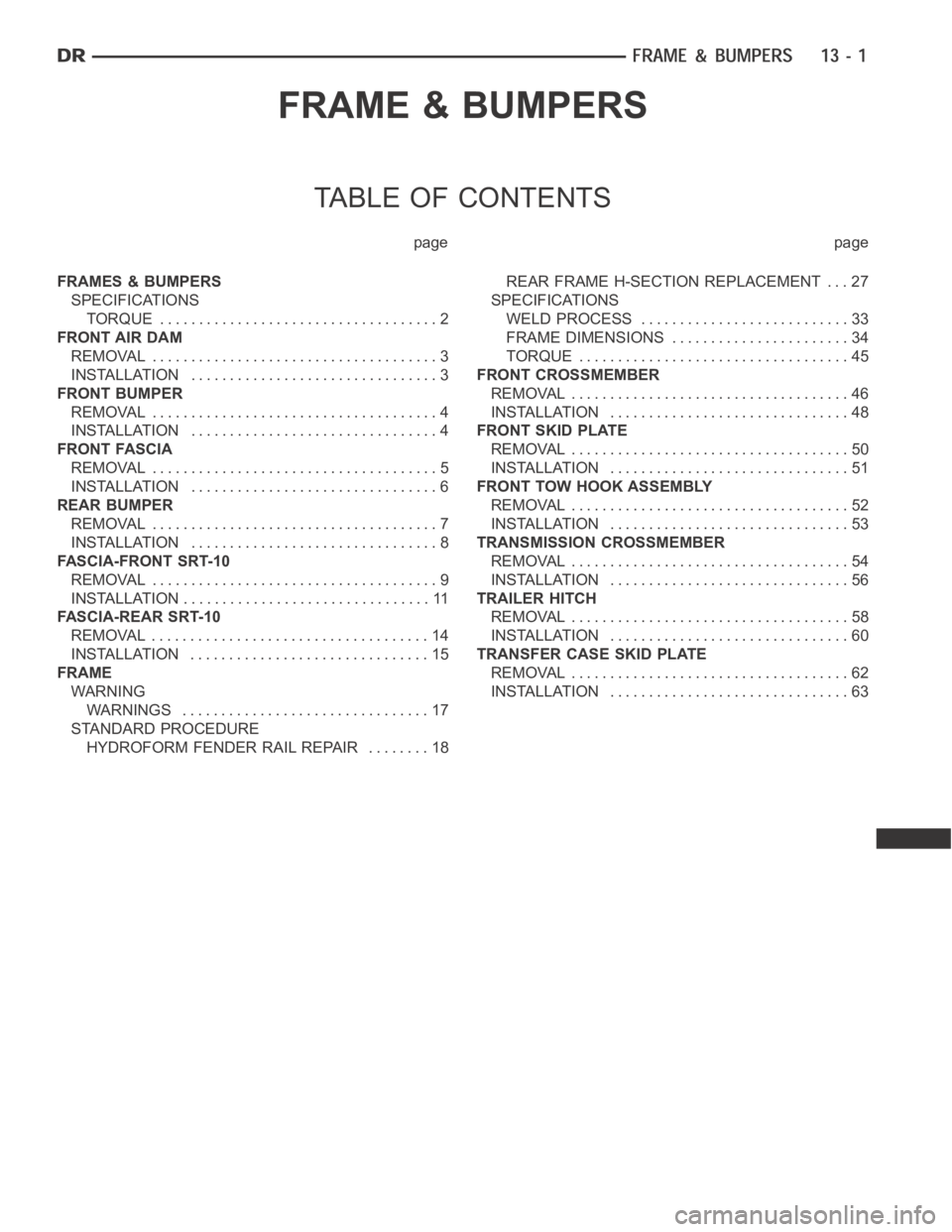
FRAME & BUMPERS
TABLE OF CONTENTS
page page
FRAMES & BUMPERS
SPECIFICATIONS
TORQUE .................................... 2
FRONT AIR DAM
REMOVAL ..................................... 3
INSTALLATION ................................ 3
FRONT BUMPER
REMOVAL ..................................... 4
INSTALLATION ................................ 4
FRONT FASCIA
REMOVAL ..................................... 5
INSTALLATION ................................ 6
REAR BUMPER
REMOVAL ..................................... 7
INSTALLATION ................................ 8
FASCIA-FRONT SRT-10
REMOVAL ..................................... 9
INSTALLATION ................................ 11
FASCIA-REAR SRT-10
REMOVAL .................................... 14
INSTALLATION ............................... 15
FRAME
WARNING
WARNINGS ................................ 17
STANDARD PROCEDURE
HYDROFORM FENDER RAIL REPAIR ........ 18REAR FRAME H-SECTION REPLACEMENT . . . 27
SPECIFICATIONS
WELD PROCESS ........................... 33
FRAME DIMENSIONS ....................... 34
TORQUE ................................... 45
FRONT CROSSMEMBER
REMOVAL .................................... 46
INSTALLATION ............................... 48
FRONT SKID PLATE
REMOVAL .................................... 50
INSTALLATION ............................... 51
FRONT TOW HOOK ASSEMBLY
REMOVAL .................................... 52
INSTALLATION ............................... 53
TRANSMISSION CROSSMEMBER
REMOVAL .................................... 54
INSTALLATION ............................... 56
TRAILER HITCH
REMOVAL .................................... 58
INSTALLATION ............................... 60
TRANSFER CASE SKID PLATE
REMOVAL .................................... 62
INSTALLATION ............................... 63
Page 2180 of 5267
REAR BUMPER
REMOVAL
1. Raise and support the vehicle (Refer to LUBRICA-
TION & MAINTENANCE/HOISTING - STANDARD
PROCEDURE).
2. Remove the license plate.
3. Remove the bolts behind the plate.
4. Disconnect the license plate light electrical connec-
tors.
5. Disconnect the trailer light connector electrical con-
nection (if equipped).
6. Remove the two bolts along the front upper edge
of the bumper near the frame tips.
7. Support the bumper with a suitable lifting device.
8. Remove the bolts attaching the bumper support
brackets (4) to the trailer hitch (1).
Page 2181 of 5267
INSTALLATION
1. Align the holes in the bumpers to the trailer hitch
pins and install the bumper.
2. Loosely install the hitch bolts (2) in the support
bracket (4).
3. Install the front upper edge to the trailer hitch bolts
(2)andtightento54Nꞏm(40ft.lbs.).
4. Install the license plate reinforcement to hitch bolts
(2)andtightento54Nꞏm(40ft.lbs.).
5. Tighten the left bumper bracket bolts (3) to 54 Nꞏm
(40 ft. lbs.).
6. Tighten the right bumper bracket bolts (3) to 54
Nꞏm (40 ft. lbs.).
7. Connect the trailer light connector electrical con-
nection (if equipped).
8. Connect the license plate light electrical connec-
tors.
9. Install the license plate.
Page 2201 of 5267
2. Disconnect and isolate the battery negative cable.
3. Remove the cargo box (1) (Refer to 23 - BODY/
EXTERIOR/CARGO BOX - REMOVAL).
4. Removethetrailerhitch(1)(Referto13-FRAME
& BUMPERS/FRAME/TRAILER HITCH -
REMOVAL).
Page 2205 of 5267
24. Lift the axle into position and install the rear
shackle bolts (6).
25. Tighten the bolts to 163 Nꞏm (120 ft. lbs.).
26. Install the lower shock absorber bolts (Refer to 2 -
SUSPENSION/REAR/SHOCK - INSTALLATION).
27. Install the trailer hitch (1) (Refer to 13 - FRAME &
BUMPERS/FRAME/TRAILER HITCH -
INSTALLATION).
Page 2218 of 5267
TORQUE
TORQUE SPECIFICATIONS
DESCRIPTION Nꞏm Ft. Lbs.
Cab mount bolts 81 60
Cargo box bolts 108 80
Front crossmember bolts - 2WD (light duty only) 61 45
Front crossmember bolts - 2WD (heavy duty only) 75 55
Front crossmember bolts - 4WD (light duty only) 102 75
Front skid plate bolts 34 25
Lower bumper support bracket bolt 54 40
Radiator crossmember bolts - lower 28 21
Radiator crossmember bolts - upper 28 21
Rear crossmember (light duty only) 102 75
Rear crossmember (heavy duty only) 115 85
Rear spring shackle bolts 163 120
Sparetirewinchbolts 41 30
Trailer hitch reinforcement bracket bolt 170 125
Transfercase skid plate bolts 34 25
Transercase skid plate crossmember bolts 34 25
Transmission mount to crossmember nuts 54 40
Page 2231 of 5267
TRAILER HITCH
REMOVAL
1. Remove the rear bumper (Refer to 13 -FRAME & BUMPERS/BUMPERS/REAR BUMPER-REMOVAL).
2. OnLight Duty Vehicles, remove the hitch bolts (7)
Page 2732 of 5267

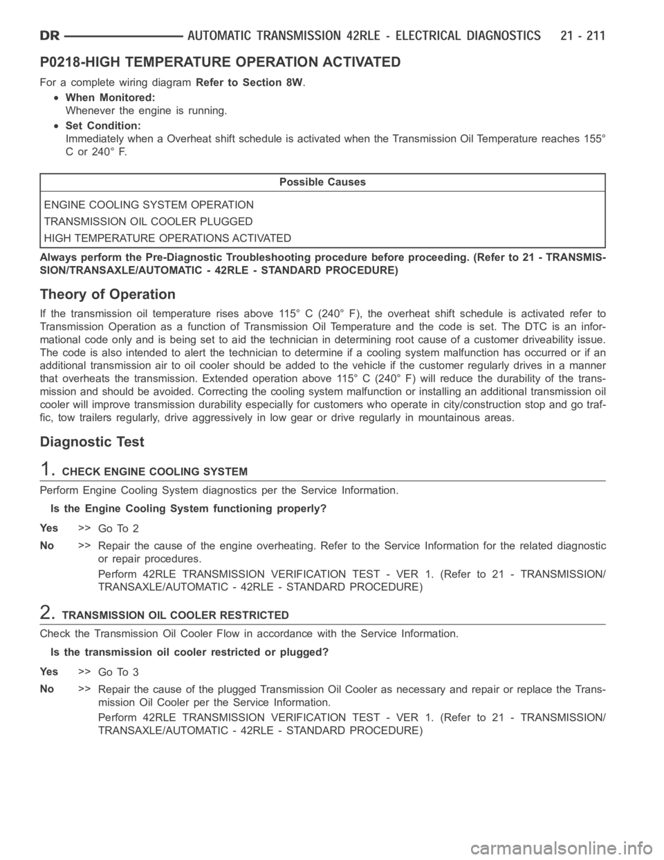
P0218-HIGH TEMPERATURE OPERATION ACTIVATED
For a complete wiring diagramRefer to Section 8W.
When Monitored:
Whenever the engine is running.
Set Condition:
Immediately when a Overheat shift schedule is activated when the Transmission Oil Temperature reaches 155°
C or 240° F.
Possible Causes
ENGINE COOLING SYSTEM OPERATION
TRANSMISSION OIL COOLER PLUGGED
H I G H T E M P E R AT U R E O P E R AT I O N S A C T I VAT E D
Always perform the Pre-Diagnostic Troubleshooting procedure before proceeding. (Refer to 21 - TRANSMIS-
SION/TRANSAXLE/AUTOMATIC - 42RLE - STANDARD PROCEDURE)
Theory of Operation
If the transmission oil temperature rises above 115° C (240° F), the overheat shift schedule is activated refer to
Transmission Operation as a function of Transmission Oil Temperature andthe code is set. The DTC is an infor-
mational code only and is being set to aid the technician in determining root cause of a customer driveability issue.
The code is also intended to alert the technician to determine if a cooling system malfunction has occurred or if an
additional transmission air to oil cooler should be added to the vehicle ifthe customer regularly drives in a manner
that overheats the transmission. Extended operation above 115° C (240° F)will reduce the durability of the trans-
mission and should be avoided. Correcting the cooling system malfunctionor installing an additional transmission oil
cooler will improve transmission durability especially for customers who operate in city/construction stop and go traf-
fic, tow trailers regularly, drive aggressively in low gear or drive regularly in mountainous areas.
Diagnostic Test
1.CHECK ENGINE COOLING SYSTEM
Perform Engine Cooling System diagnostics per the Service Information.
Is the Engine Cooling System functioning properly?
Ye s>>
Go To 2
No>>
Repair the cause of the engine overheating. Refer to the Service Information for the related diagnostic
or repair procedures.
Perform 42RLE TRANSMISSION VERIFICATION TEST - VER 1. (Refer to 21 - TRANSMISSION/
TRANSAXLE/AUTOMATIC - 42RLE - STANDARD PROCEDURE)
2.TRANSMISSION OIL COOLER RESTRICTED
Check the Transmission Oil Cooler Flow in accordance with the Service Information.
Is the transmission oil cooler restricted or plugged?
Ye s>>
Go To 3
No>>
Repair the cause of the plugged Transmission Oil Cooler as necessary and repair or replace the Trans-
mission Oil Cooler per the Service Information.
Perform 42RLE TRANSMISSION VERIFICATION TEST - VER 1. (Refer to 21 - TRANSMISSION/
TRANSAXLE/AUTOMATIC - 42RLE - STANDARD PROCEDURE)