2006 DODGE RAM SRT-10 roof
[x] Cancel search: roofPage 1960 of 5267
ENGINE BLOCK
STANDARD PROCEDURE
STANDARD PROCEDURE - CYLINDER BLOCK REFACING
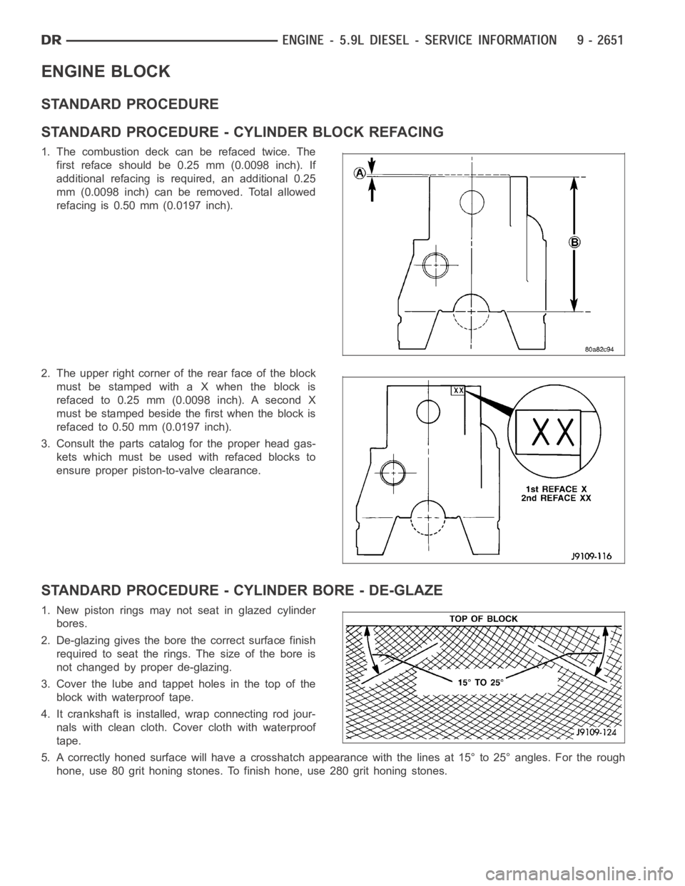
1. The combustion deck can be refaced twice. The
first reface should be 0.25 mm (0.0098 inch). If
additional refacing is required, an additional 0.25
mm (0.0098 inch) can be removed. Total allowed
refacing is 0.50 mm (0.0197 inch).
2. The upper right corner of the rear face of the block
must be stamped with a X when the block is
refaced to 0.25 mm (0.0098 inch). A second X
must be stamped beside the first when the block is
refacedto0.50mm(0.0197inch).
3. Consult the parts catalog for the proper head gas-
kets which must be used with refaced blocks to
ensure proper piston-to-valve clearance.
STANDARD PROCEDURE - CYLINDER BORE - DE-GLAZE
1. New piston rings may not seat in glazed cylinder
bores.
2. De-glazing gives the bore the correct surface finish
required to seat the rings. The size of the bore is
not changed by proper de-glazing.
3. Cover the lube and tappet holes in the top of the
block with waterproof tape.
4. It crankshaft is installed, wrap connecting rod jour-
nals with clean cloth. Cover cloth with waterproof
tape.
5. A correctly honed surface will have a crosshatch appearance with the lines at 15° to 25° angles. For the rough
hone, use 80 grit honing stones. To finish hone, use 280 grit honing stones.
Page 4338 of 5267
BODY
TABLE OF CONTENTS
page page
BODY
WARNING
SAFETY PRECAUTIONS AND WARNINGS ..... 2
DIAGNOSIS AND TESTING
WATER LEAKS .............................. 2
WIND NOISE ................................ 3
STANDARD PROCEDURE
BODY LUBRICATION ......................... 4
HEAT STAKING .............................. 4
BUZZ, SQUEAK & RATTLE ................... 4
PLASTIC BODY PANEL REPAIR ............... 5
SPECIFICATIONS
TORQUE ................................... 14
SPECIAL TOOLS
BODY ...................................... 16TA I L G AT E..............................17
DOOR - FRONT.........................28
DOORS - REAR.........................56
EXTERIOR.............................86
HOOD................................126
INSTRUMENT PANEL....................138
INTERIOR.............................176
PA I N T................................215
SEATS...............................221
STATIONARY GLASS....................256
SUNROOF - SERVICE INFORMATION.......270
WEATHERSTRIP/SEALS..................300
WINCH...............................320
BODY STRUCTURE.....................361
Page 4341 of 5267
POSSIBLE CAUSE OF WIND NOISE
Moldings standing away from body surface can catch wind and whistle.
Gaps in sealed areas behind overhanging body flanges can cause wind-rushing sounds.
Misaligned movable components.
Missing or improperly installed plugs in pillars.
Weld burn through holes.
Improperly installed roof rack cross bars.
STANDARD PROCEDURE
BODY LUBRICATION
All mechanisms and linkages should be lubricated when necessary. This will maintain ease of operation and provide
protection against rust and excessive wear. The weatherstrip seals should be lubricated to prolong their life as well
as to improve door sealing.
All applicable exterior and interior vehicle operating mechanisms should be inspected and cleaned. Pivot/sliding con-
tact areas on the mechanisms should then be lubricated.
1. When necessary, lubricate the operating mechanisms with the specifiedlubricants.
2. Apply silicone lubricant to a clothand wipe it on door seals to avoid over-spray that can soil passenger’s cloth-
ing.
3. Before applying lubricant, the component should be wiped clean. After lubrication, any excess lubricant should be
removed.
4. The hood latch, latch release mechanism, latch striker, and safety latch should be lubricated periodically.
5. The door lock cylinders should be lubricated twice each year (preferably autumn and spring).
Spray a small amount of lock cylinder lubricant directly into the lock cylinder.
Apply a small amount to the key and insert it into the lock cylinder.
Rotate it to the locked position and then back to the unlocked position several times.
Remove the key. Wipe the lubricant from it with a clean cloth to avoid soiling of clothing.
HEAT STAKING
1. Remove trim panel.
2. Bend or move the trim panel components at the heat staked joints. Observethe heat staked locations and/or
component seams for looseness.
3. Heat stake the components.
a. If the heat staked or component seam location is loose, hold the two components tightly together and using
a soldering gun with a flat tip, melt the material securing the components together. Do not over heat the
affected area, damage to the exterior of the trim panel may occur.
b. Iftheheatstakedmaterialisbrokenormissing,useahotglueguntoapplynewmaterialtotheareatobe
repaired. The panels that are being heat staked must be held together whiletheapplyingtheglue.Oncethe
new material is in place, it may be necessary to use a soldering gun to melt the newly applied material. Do
not over heat the affected area, damage to the exterior of the trim panel mayoccur.
4. Allow the repaired area to cool and verify the repair.
5. Install trim panel.
BUZZ, SQUEAK & RATTLE
Buzz, Squeak & Rattles (BSR) may be caused by any one or more of the followingand may be corrected as indi-
cated:
Loose fasteners should be tightened to specifications.
Damaged or missing clips should be replaced.
Damaged trim panels should be replaced.
Incorrectly installed trim panels should be reinstalled properly.
Page 4366 of 5267
DOOR
REMOVAL
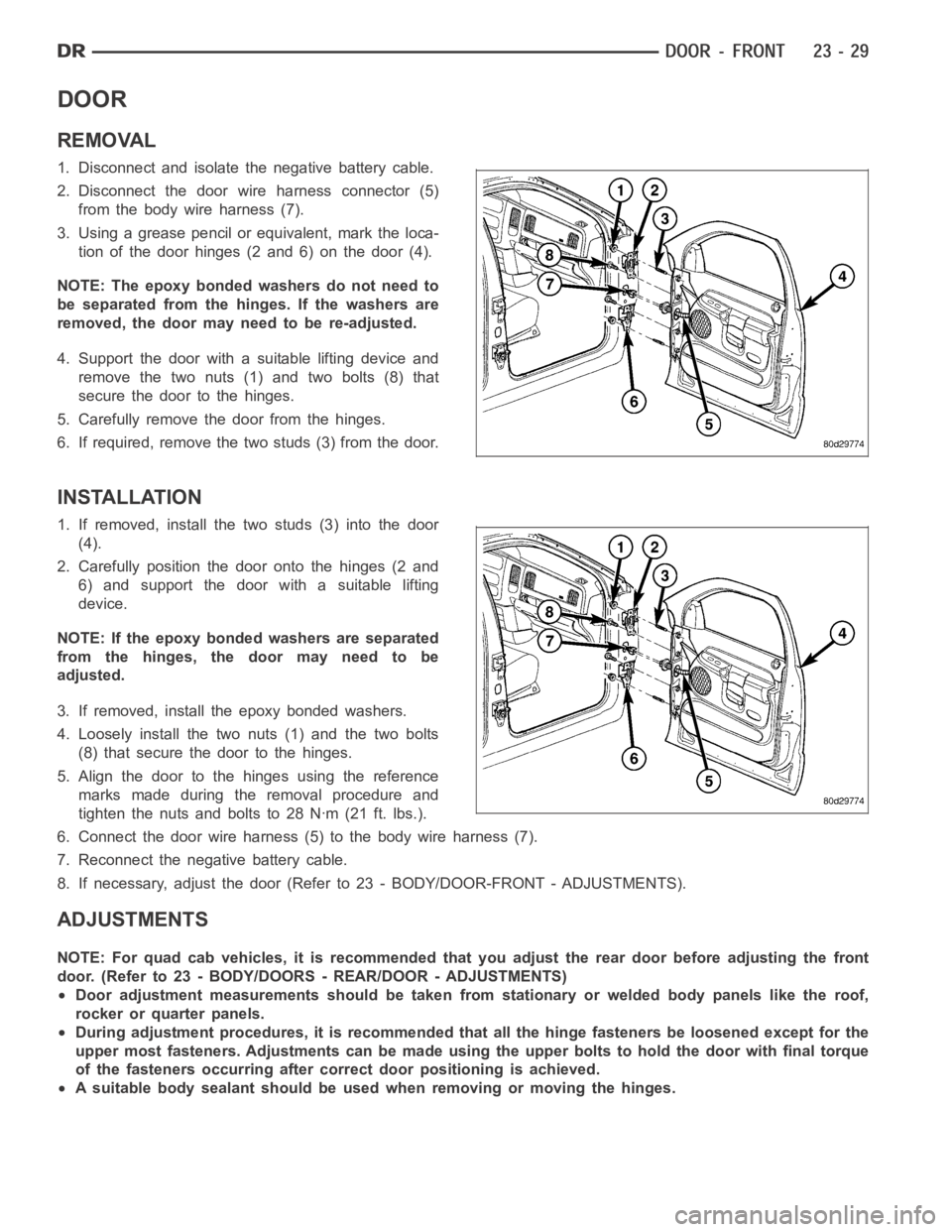
1. Disconnect and isolate the negative battery cable.
2. Disconnect the door wire harness connector (5)
from the body wire harness (7).
3. Using a grease pencil or equivalent, mark the loca-
tion of the door hinges (2 and 6) on the door (4).
NOTE: The epoxy bonded washers do not need to
be separated from the hinges. If the washers are
removed,thedoormayneedtobere-adjusted.
4. Support the door with a suitable lifting device and
remove the two nuts (1) and two bolts (8) that
secure the door to the hinges.
5. Carefully remove the door from the hinges.
6. If required, remove the two studs (3) from the door.
INSTALLATION
1. If removed, install the two studs (3) into the door
(4).
2. Carefully position the door onto the hinges (2 and
6) and support the door with a suitable lifting
device.
NOTE: If the epoxy bonded washers are separated
from the hinges, the door may need to be
adjusted.
3. If removed, install the epoxy bonded washers.
4. Loosely install the two nuts (1) and the two bolts
(8) that secure the door to the hinges.
5. Align the door to the hinges using the reference
marks made during the removal procedure and
tighten the nuts and bolts to 28 Nꞏm (21 ft. lbs.).
6. Connect the door wire harness (5) to the body wire harness (7).
7. Reconnect the negative battery cable.
8. If necessary, adjust the door (Refer to 23 - BODY/DOOR-FRONT - ADJUSTMENTS).
ADJUSTMENTS
NOTE: For quad cab vehicles, it is recommended that you adjust the rear doorbefore adjusting the front
door. (Refer to 23 - BODY/DOORS - REAR/DOOR - ADJUSTMENTS)
Door adjustment measurements should be taken from stationary or welded body panels like the roof,
rocker or quarter panels.
During adjustment procedures, it is recommended that all the hinge fasteners be loosened except for the
upper most fasteners. Adjustments can be made using the upper bolts to holdthe door with final torque
of the fasteners occurring after correct door positioning is achieved.
A suitable body sealant should be used when removing or moving the hinges.
Page 4367 of 5267
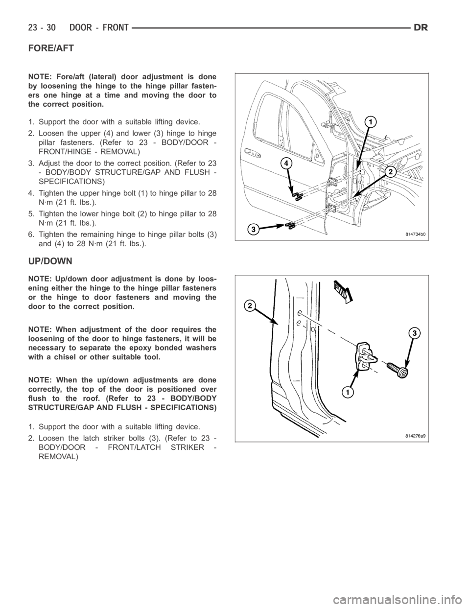
FORE/AFT
NOTE: Fore/aft (lateral) door adjustment is done
by loosening the hinge to the hinge pillar fasten-
ers one hinge at a time and moving the door to
the correct position.
1. Support the door with a suitable lifting device.
2. Loosen the upper (4) and lower (3) hinge to hinge
pillar fasteners. (Refer to 23 - BODY/DOOR -
FRONT/HINGE - REMOVAL)
3. Adjust the door to the correct position. (Refer to 23
- BODY/BODY STRUCTURE/GAP AND FLUSH -
SPECIFICATIONS)
4. Tighten the upper hinge bolt (1) to hinge pillar to 28
Nꞏm (21 ft. lbs.).
5. Tighten the lower hinge bolt (2) to hinge pillar to 28
Nꞏm (21 ft. lbs.).
6. Tighten the remaining hinge to hinge pillar bolts (3)
and(4)to28Nꞏm(21ft.lbs.).
UP/DOWN
NOTE: Up/down door adjustment is done by loos-
ening either the hinge to the hinge pillar fasteners
or the hinge to door fasteners and moving the
door to the correct position.
NOTE: When adjustment of the door requires the
loosening of the door to hinge fasteners, it will be
necessary to separate the epoxy bonded washers
with a chisel or other suitable tool.
NOTE: When the up/down adjustments are done
correctly, the top of the door is positioned over
flush to the roof. (Refer to 23 - BODY/BODY
STRUCTURE/GAP AND FLUSH - SPECIFICATIONS)
1. Support the door with a suitable lifting device.
2. Loosen the latch striker bolts (3). (Refer to 23 -
BODY/DOOR - FRONT/LATCH STRIKER -
REMOVAL)
Page 4395 of 5267
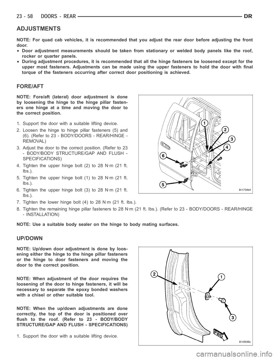
ADJUSTMENTS
NOTE: For quad cab vehicles, it is recommended that you adjust the rear doorbefore adjusting the front
door.
Door adjustment measurements should be taken from stationary or welded body panels like the roof,
rocker or quarter panels.
During adjustment procedures, it is recommended that all the hinge fasteners be loosened except for the
upper most fasteners. Adjustments can be made using the upper fasteners tohold the door with final
torque of the fasteners occurring after correct door positioning is achieved.
FORE/AFT
NOTE: Fore/aft (lateral) door adjustment is done
by loosening the hinge to the hinge pillar fasten-
ers one hinge at a time and moving the door to
the correct position.
1. Support the door with a suitable lifting device.
2. Loosen the hinge to hinge pillar fasteners (5) and
(6). (Refer to 23 - BODY/DOORS - REAR/HINGE -
REMOVAL)
3. Adjust the door to the correct position. (Refer to 23
- BODY/BODY STRUCTURE/GAP AND FLUSH -
SPECIFICATIONS)
4. Tighten the upper hinge bolt (2) to 28 Nꞏm (21 ft.
lbs.).
5. Tighten the upper hinge bolt (1) to 28 Nꞏm (21 ft.
lbs.).
6. Tighten the upper hinge bolt (3) to 28 Nꞏm (21 ft.
lbs.).
7. Tighten the lower hinge bolt (4) to 28 Nꞏm (21 ft. lbs.).
8. Tighten the remaining hinge pillar fasteners to 28 Nꞏm (21 ft. lbs.). (Refer to 23 - BODY/DOORS - REAR/HINGE
- INSTALLATION)
NOTE: Use a suitable body sealer on the hinge to body mating surfaces.
UP/DOWN
NOTE: Up/down door adjustment is done by loos-
ening either the hinge to the hinge pillar fasteners
or the hinge to door fasteners and moving the
door to the correct position.
NOTE: When adjustment of the door requires the
loosening of the door to hinge fasteners, it will be
necessary to separate the epoxy bonded washers
with a chisel or other suitable tool.
NOTE: When the up/down adjustments are done
correctly, the top of the door is positioned over
flush to the roof. (Refer to 23 - BODY/BODY
STRUCTURE/GAP AND FLUSH - SPECIFICATIONS)
1. Support the door with a suitable lifting device.
Page 4531 of 5267
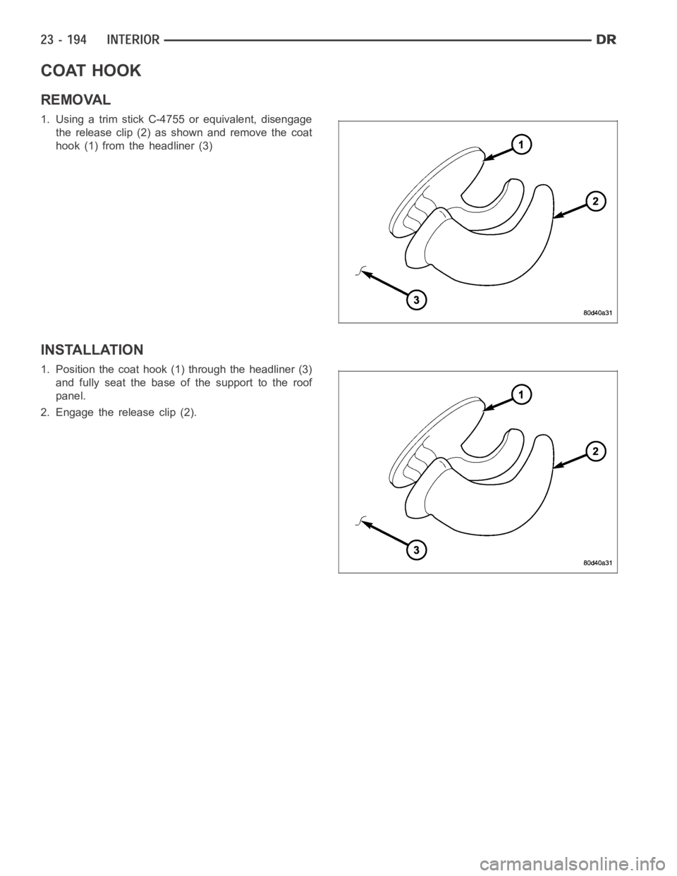
COAT HOOK
REMOVAL
1. Using a trim stick C-4755 or equivalent, disengage
the release clip (2) as shown and remove the coat
hook (1) from the headliner (3)
INSTALLATION
1. Position the coat hook (1) through the headliner (3)
and fully seat the base of the support to the roof
panel.
2. Engage the release clip (2).
Page 4539 of 5267
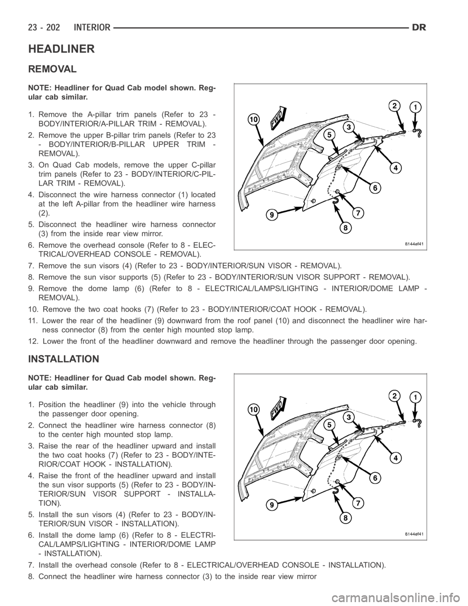
HEADLINER
REMOVAL
NOTE: Headliner for Quad Cab model shown. Reg-
ular cab similar.
1. Remove the A-pillar trim panels (Refer to 23 -
BODY/INTERIOR/A-PILLAR TRIM - REMOVAL).
2. Remove the upper B-pillar trim panels (Refer to 23
- BODY/INTERIOR/B-PILLAR UPPER TRIM -
REMOVAL).
3. On Quad Cab models, remove the upper C-pillar
trim panels (Refer to 23 - BODY/INTERIOR/C-PIL-
LAR TRIM - REMOVAL).
4. Disconnect the wire harness connector (1) located
at the left A-pillar from the headliner wire harness
(2).
5. Disconnect the headliner wire harness connector
(3) from the inside rear view mirror.
6. Remove the overhead console (Refer to 8 - ELEC-
TRICAL/OVERHEAD CONSOLE - REMOVAL).
7. Remove the sun visors (4) (Refer to 23 - BODY/INTERIOR/SUN VISOR - REMOVAL).
8. Remove the sun visor supports (5) (Refer to 23 - BODY/INTERIOR/SUN VISORSUPPORT - REMOVAL).
9. Remove the dome lamp (6) (Refer to 8 -ELECTRICAL/LAMPS/LIGHTING - INTERIOR/DOME LAMP -
REMOVAL).
10. Remove the two coat hooks (7) (Refer to 23 - BODY/INTERIOR/COAT HOOK - REMOVAL).
11. Lower the rear of the headliner (9) downward from the roof panel (10) anddisconnect the headliner wire har-
ness connector (8) from the center high mounted stop lamp.
12. Lower the front of the headliner downward and remove the headliner through the passenger door opening.
INSTALLATION
NOTE: Headliner for Quad Cab model shown. Reg-
ular cab similar.
1. Position the headliner (9) into the vehicle through
the passenger door opening.
2. Connect the headliner wire harness connector (8)
to the center high mounted stop lamp.
3. Raise the rear of the headliner upward and install
the two coat hooks (7) (Refer to 23 - BODY/INTE-
RIOR/COAT HOOK - INSTALLATION).
4. Raise the front of the headliner upward and install
the sun visor supports (5) (Refer to 23 - BODY/IN-
TERIOR/SUN VISOR SUPPORT - INSTALLA-
TION).
5. Install the sun visors (4) (Refer to 23 - BODY/IN-
TERIOR/SUN VISOR - INSTALLATION).
6. Install the dome lamp (6) (Refer to 8 - ELECTRI-
CAL/LAMPS/LIGHTING - INTERIOR/DOME LAMP
- INSTALLATION).
7. Install the overhead console (Refer to 8 - ELECTRICAL/OVERHEAD CONSOLE-INSTALLATION).
8. Connect the headliner wire harness connector (3) to the inside rear viewmirror