2006 DODGE RAM SRT-10 power steering fluid
[x] Cancel search: power steering fluidPage 1971 of 5267
12. Install gear housing cover (Refer to 9 - ENGINE/VALVE TIMING/GEAR HOUSING COVER - INSTALLATION).
Install front crankshaft dust seal.
13. Install the crankshaft damper with the speed indicator ring (Refer to 9- ENGINE/ENGINE BLOCK/VIBRATION
DAMPER - INSTALLATION).
14. Install the fan support/hub assembly Refer to (Refer to 7 - COOLING/ENGINE/RADIATOR FAN - INSTALLA-
TION).
15. Install the power steering pump.
16. Install accessory drive belt tensioner. Torque bolt to 43 Nꞏm (32 ft. lbs.).
17. Install the accessory drive belt (Refer to 7 - COOLING/ACCESSORY DRIVE/DRIVE BELTS - INSTALLATION).
18. Install the charge air cooler (with a/c condenser and auxiliary transmission oil cooler, if equipped) and tighten
the mounting bolts to 2 Nꞏm (17 in. lbs.) torque.
19. Connect charge air cooler inlet and outlet pipes. Tighten clamps to 11 Nꞏm (95 in. lbs.) torque.
20. Install the radiator upper support panel.
21. Close radiator petcock and lower the radiator into the engine compartment. Tighten the mounting bolts to 11
Nꞏm (95 in. lbs.) torque.
22. Raise vehicle on hoist.
23. Connect radiator lower hose and install clamp.
24. Connect transmission auxiliary oil cooler lines (if equipped).
25. Lower vehicle.
26. Install the fandrive/shroud assembly. (Refer to 7 - COOLING/ENGINE/RADIATOR FAN - INSTALLATION)
27. Install the coolant recovery and windshield washer fluid reservoirs to the fan shroud.
28. Connect the coolant recovery hose to the radiator filler neck.
29. Add engine coolant (Refer to 7 - COOLING - STANDARD PROCEDURE).
30. Charge A/C system with refrigerant (if A/C equipped) (Refer to 24 - HEATING & AIR CONDITIONING/PLUMB-
ING - STANDARD PROCEDURE).
31. Connect the battery negative cables.
32. Start engine and check for engine oil and coolant leaks.
Page 2033 of 5267
5. Identify the fluid in the cylinder(s) (i.e., coolant, fuel, oil or other).
6. Make sure all fluid has been removed from the cylinders. Inspect engine for damage (i.e., connecting rods, pis-
tons, valves, etc.)
7. Repair engine or components as necessary to prevent this problem from re-occurring.
CAUTION: Squirt approximately one teaspoon of oil into the cylinders, rotateenginetolubricatethecylin-
der walls to prevent damage on restart.
8. Install new spark plugs.
9. Drain engine oil and remove oil filter.
10. Fill engine with specified amount of approved oil and install new oil filter.
11. Connect negative battery cable.
12. Start engine and check for any leaks.
REMOVAL - ENGINE ASSEMBLY
1. Perform fuel pressure release procedure (Refer to
14 - FUEL SYSTEM/FUEL DELIVERY - STAN-
DARD PROCEDURE).
2. Disconnect negative battery cable.
3. Disconnect throttle body air inlet duct, remove air
cleaner cover (Refer to 9 - ENGINE/AIR INTAKE
SYSTEM/AIR CLEANER ELEMENT - REMOVAL).
4. Raise and support the vehicle.
5. Remove the lower engine shield.
6. Drain cooling system (Refer to 7 - COOLING/EN-
GINE - STANDARD PROCEDURE - DRAINING
COOLING SYSTEM).
7. Paint mark and remove the driveshaft (Refer to 3 -
DIFFERENTIAL & DRIVELINE/PROPELLER
SHAFT/PROPELLER SHAFT - REMOVAL).
8.Removethetransmission(Referto21-TRANS-
MISSION/TRANSAXLE/MANUAL - REMOVAL).
9. Remove the starter (Refer to 8 - ELECTRICAL/
STARTING/STARTER MOTOR - REMOVAL).
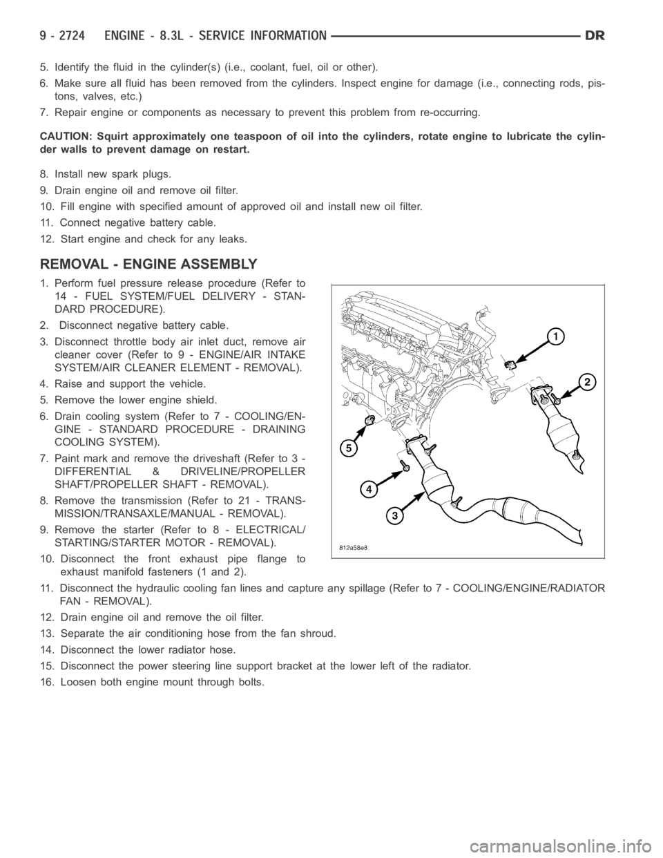
10. Disconnect the front exhaust pipe flange to
exhaust manifold fasteners (1 and 2).
11. Disconnect the hydraulic cooling fan lines and capture any spillage (Refer to 7 - COOLING/ENGINE/RADIATOR
FA N - R E M O VA L ) .
12. Drain engine oil and remove the oil filter.
13. Separate the air conditioning hose from the fan shroud.
14. Disconnect the lower radiator hose.
15. Disconnect the power steering line support bracket at the lower left ofthe radiator.
16. Loosen both engine mount through bolts.
Page 2040 of 5267
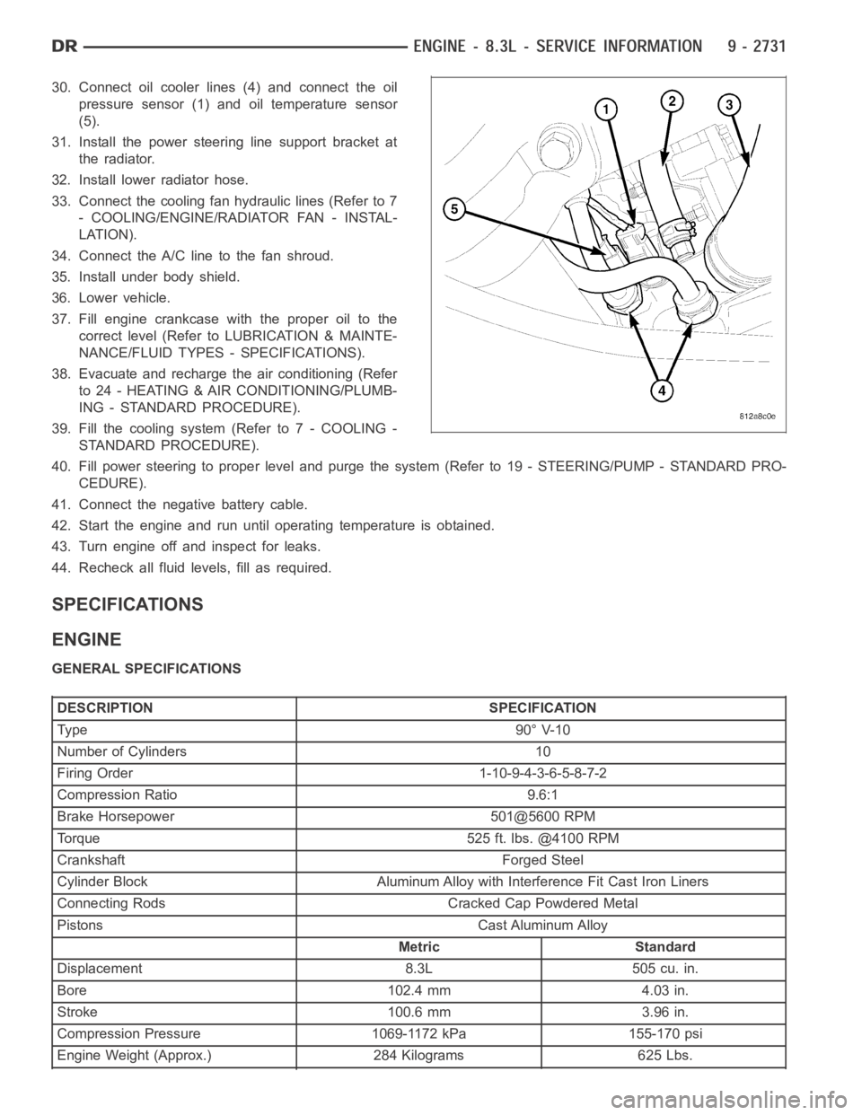
30. Connect oil cooler lines (4) and connect the oil
pressure sensor (1) and oil temperature sensor
(5).
31. Install the power steering line support bracket at
the radiator.
32. Install lower radiator hose.
33. Connect the cooling fan hydraulic lines (Refer to 7
- COOLING/ENGINE/RADIATOR FAN - INSTAL-
LATION).
34. Connect the A/C line to the fan shroud.
35. Install under body shield.
36. Lower vehicle.
37. Fill engine crankcase with the proper oil to the
correct level (Refer to LUBRICATION & MAINTE-
NANCE/FLUID TYPES - SPECIFICATIONS).
38. Evacuate and recharge the air conditioning (Refer
to 24 - HEATING & AIR CONDITIONING/PLUMB-
ING - STANDARD PROCEDURE).
39. Fill the cooling system (Refer to 7 - COOLING -
STANDARD PROCEDURE).
40. Fill power steering to proper leveland purge the system (Refer to 19 - STEERING/PUMP - STANDARD PRO-
CEDURE).
41. Connect the negative battery cable.
42. Start the engine and run until operating temperature is obtained.
43. Turn engine off and inspect for leaks.
44. Recheck all fluid levels, fill as required.
SPECIFICATIONS
ENGINE
GENERAL SPECIFICATIONS
DESCRIPTION SPECIFICATION
Ty pe 9 0° V-1 0
Number of Cylinders 10
Firing Order 1-10-9-4-3-6-5-8-7-2
Compression Ratio 9.6:1
Brake Horsepower 501@5600 RPM
Torque 525 ft. lbs. @4100 RPM
Crankshaft Forged Steel
Cylinder Block Aluminum Alloy with Interference Fit Cast Iron Liners
Connecting Rods Cracked Cap Powdered Metal
Pistons Cast Aluminum Alloy
Metric Standard
Displacement 8.3L 505 cu. in.
Bore 102.4 mm 4.03 in.
Stroke 100.6 mm 3.96 in.
Compression Pressure 1069-1172 kPa 155-170 psi
Engine Weight (Approx.) 284 Kilograms 625 Lbs.
Page 2108 of 5267
CAMSHAFT
REMOVAL
1. Perform the fuel pressure relief procedure (Refer to
14 - FUEL SYSTEM/FUEL DELIVERY - STAN-
DARD PROCEDURE).
2. Disconnect the negative battery cable.
3. Raise and support the vehicle.
4. Remove the front engine shield.
5. Drain the cooling system
6. Drain the power steering fluid.
7. Remove the oil pan (Refer to 9 - ENGINE/LUBRI-
CATION/OIL PAN - REMOVAL).
8. Lower the vehicle.
9. Remove the radiator and radiator fan assembly
(Refer to 7 - COOLING/ENGINE/RADIATOR -
REMOVAL).
10. Remove intake manifold (Refer to 9 - ENGINE/
MANIFOLDS/INTAKE MANIFOLD - REMOVAL).
11. Remove cylinder head covers (Refer to 9 -
ENGINE/CYLINDER HEAD/CYLINDER HEAD
COVER(S) - REMOVAL).
12. Remove timing chain cover (Refer to 9 - ENGINE/
VALVE TIMING/TIMING CHAIN COVER - REMOVAL).
13. Remove rocker arm assemblies.
NOTE: Identify each push rod to be replaced in its original location.
14. Remove push rods.
15. Remove cylinder heads (Refer to 9 - ENGINE/CYLINDER HEAD - REMOVAL).
16. Remove hydraulic tappets (Refer to 9 - ENGINE/ENGINE BLOCK/HYDRAULICTAPPETS - REMOVAL).
17. Remove timing chain and camshaft sprocket (Refer to 9 - ENGINE/VALVE TIMING/TIMING CHAIN AND
SPROCKETS - REMOVAL).
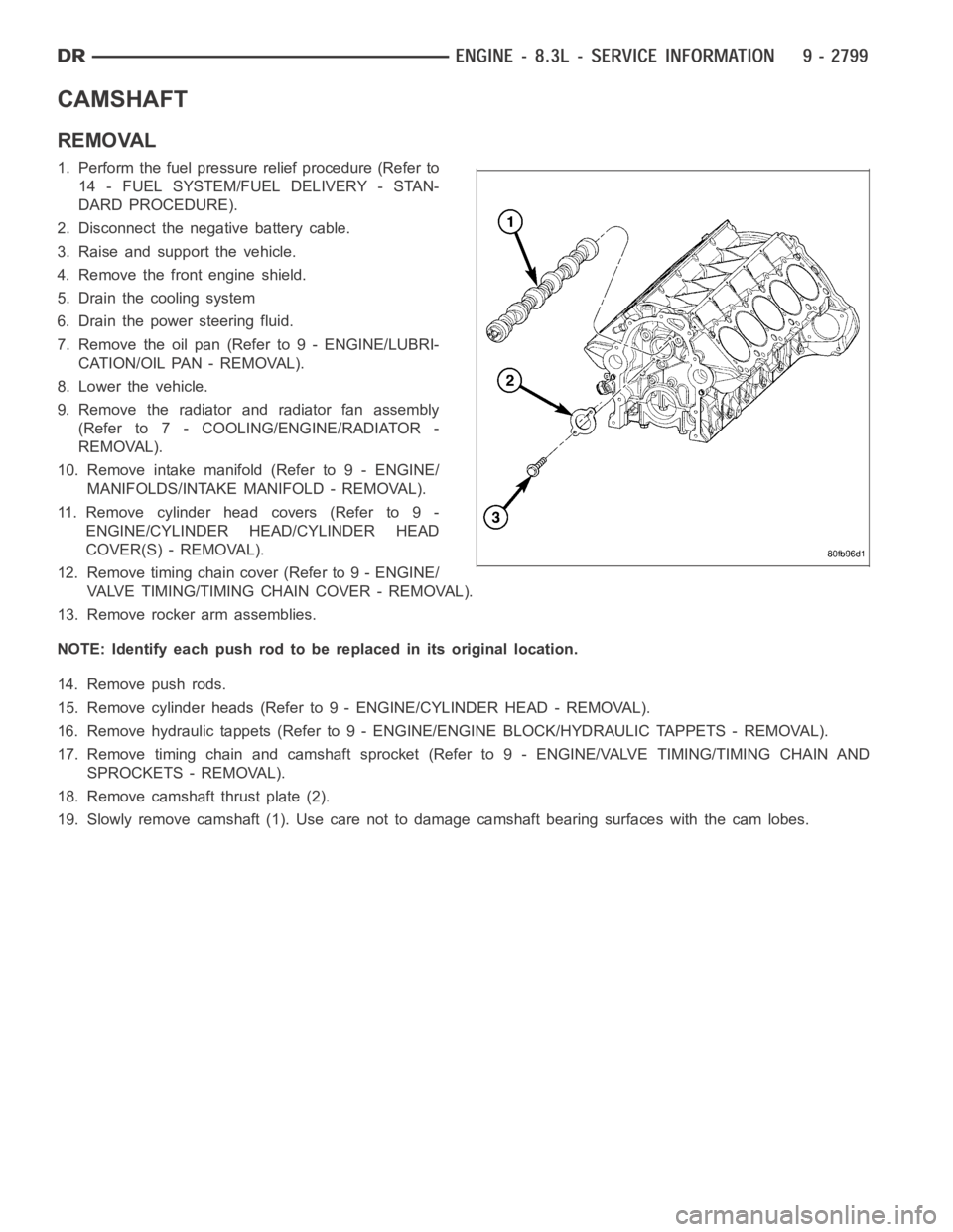
18. Remove camshaft thrust plate (2).
19. Slowly remove camshaft (1). Use care not to damage camshaft bearing surfaces with the cam lobes.
Page 2407 of 5267
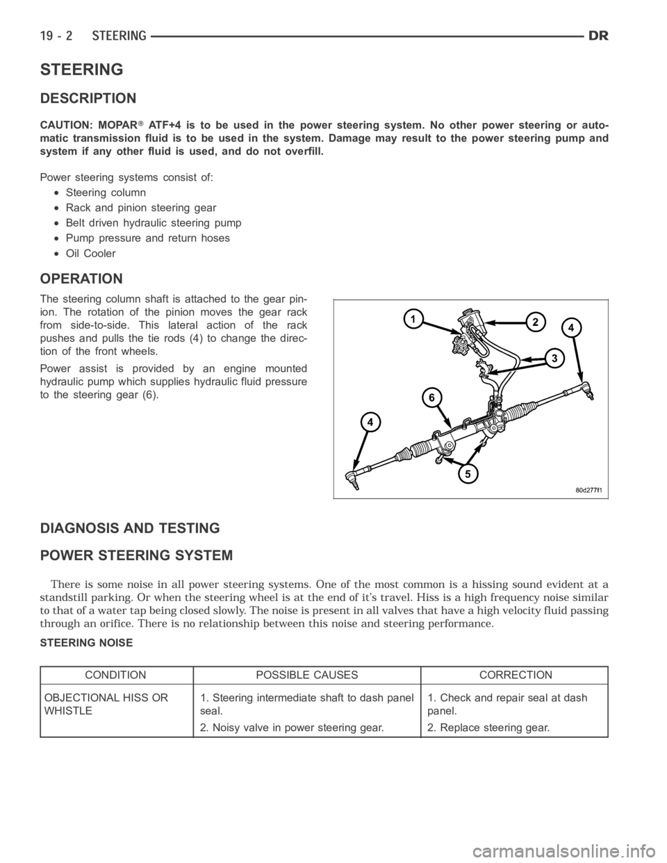
STEERING
DESCRIPTION
CAUTION: MOPARATF+4 is to be used in the power steering system. No other power steering or auto-
matic transmission fluid is to be used in the system. Damage may result to the power steering pump and
system if any other fluid is used, and do not overfill.
Power steering systems consist of:
Steering column
Rack and pinion steering gear
Belt driven hydraulic steering pump
Pump pressure and return hoses
Oil Cooler
OPERATION
The steering column shaft isattached to the gear pin-
ion. The rotation of the pinion moves the gear rack
from side-to-side. This lateral action of the rack
pushes and pulls the tie rods (4) to change the direc-
tion of the front wheels.
Power assist is provided by an engine mounted
hydraulic pump which supplies hydraulic fluid pressure
to the steering gear (6).
DIAGNOSIS AND TESTING
POWER STEERING SYSTEM
STEERING NOISE
CONDITION POSSIBLE CAUSES CORRECTION
OBJECTIONAL HISS OR
WHISTLE1. Steering intermediate shaft to dash panel
seal.1. Check and repair seal at dash
panel.
2. Noisy valve in power steering gear. 2. Replace steering gear.
Page 2409 of 5267
INSUFFICIENT ASST. OR POOR RETURN TO CENTER
CONDITION POSSIBLE CAUSE CORRECTION
HARD TURNING OR MOMENTARY
INCREASE IN TURNING EFFORT1. Tire pressure. 1. Adjust tire pressure.
2. Low fluid level. 2. Fill to proper level.
3. Loose belt. 3. Adjust or replace.
4. Low pump pressure. 4. Pressure test and repair as
necessary.
5. Internal gear leak. 5. Replace gear.
STEERING WHEEL DOES NOT
WANT TO RETURN TO CENTER
POSITION1. Tire pressure. 1. Adjust tire pressure.
2. Wheel alignment. 2. Align front end.
3. Lack of lubrication. 3. Inspect and lubricate suspension
components.
4. High friction in steering gear. 4. Replace gear.
LOOSE STEERING AND VEHICLE LEAD
CONDITION POSSIBLE CAUSE CORRECTION
EXCESSIVE PLAY IN STEERING
WHEEL1. Worn or loose suspension or
steering components.1. Inspect and repair as necessary.
2. Worn or loose wheel bearings. 2. Inspect and repair or adjust
bearings.
3. Steering gear mounting. 3. Tighten gear mounting bolts to
specification.
4. Gear out of adjustment. 4. Replace gear.
5. Worn or loose steering coupler. 5. Inspect and replace as
necessary.
VEHICLE PULLS OR LEADS TO
ONE SIDE.1. Tire Pressure. 1. Adjust tire pressure.
2. Radial tire lead. 2. Rotate tires.
3. Brakes dragging. 3. Repair as necessary.
4. Wheel alignment. 4. Align front end.
5. Steering gear valve bias. 5. Replace steering gear.
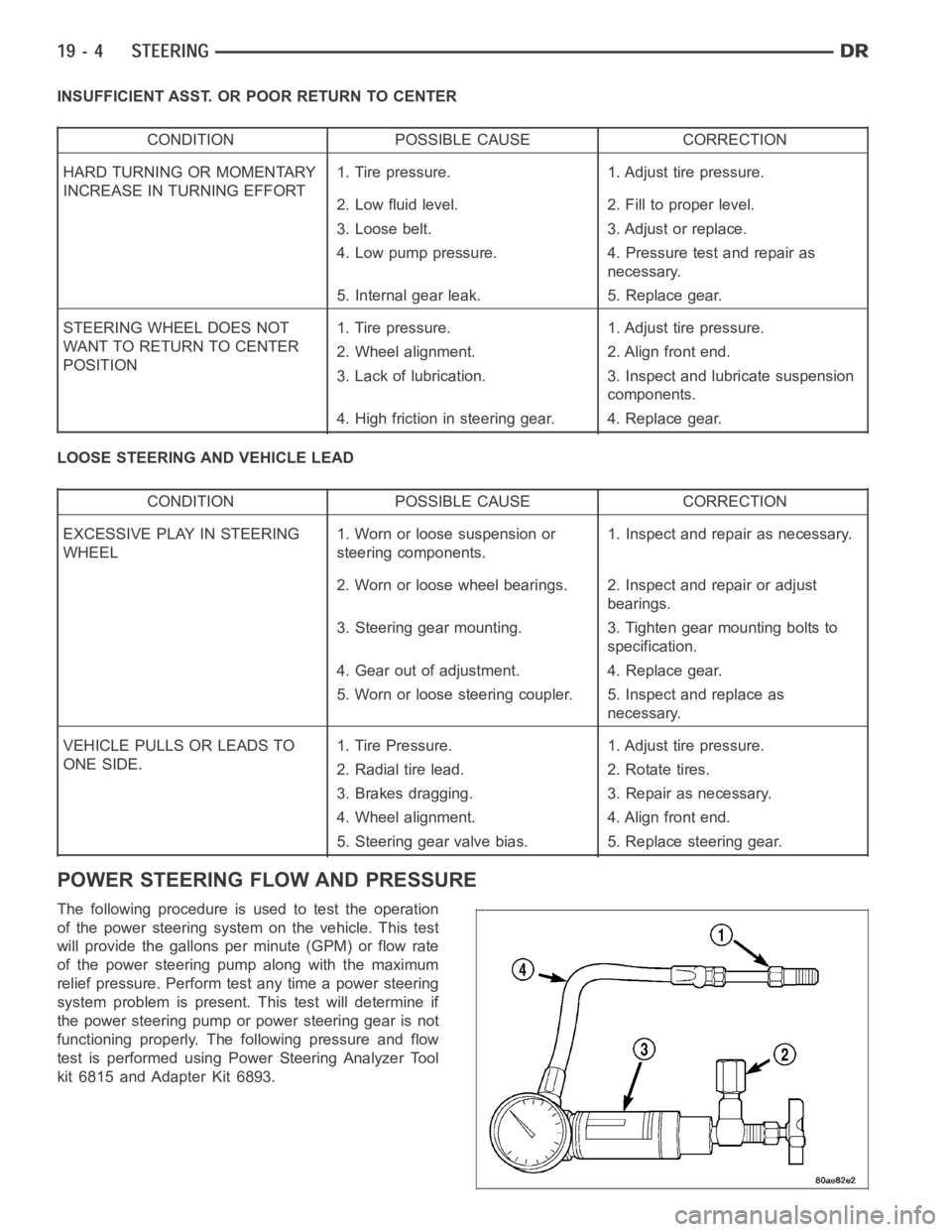
POWER STEERING FLOW AND PRESSURE
The following procedure is used to test the operation
of the power steering system on the vehicle. This test
will provide the gallons per minute (GPM) or flow rate
of the power steering pump along with the maximum
relief pressure. Perform test any time a power steering
system problem is present. This test will determine if
the power steering pump or power steering gear is not
functioning properly. The following pressure and flow
test is performed using Power Steering Analyzer Tool
kit 6815 and Adapter Kit 6893.
Page 2410 of 5267
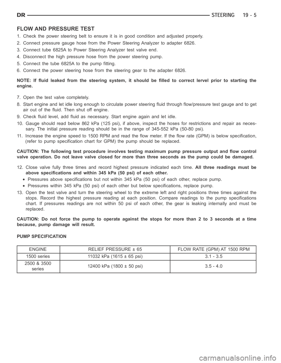
FLOW AND PRESSURE TEST
1. Check the power steering belt to ensure it is in good condition and adjusted properly.
2. Connect pressure gauge hose from the Power Steering Analyzer to adapter6826.
3. Connect tube 6825A to Power Steering Analyzer test valve end.
4. Disconnect the high pressure hose from the power steering pump.
5. Connect the tube 6825A to the pump fitting.
6. Connect the power steering hose from the steering gear to the adapter 6826.
NOTE: If fluid leaked from the steering system, it should be filled to correct lervel prior to starting the
engine.
7. Open the test valve completely.
8. Start engine and let idle long enough to circulate power steering fluid through flow/pressure test gauge and to get
air out of the fluid. Then shut off engine.
9. Check fluid level, add fluid as necessary. Start engine again and let idle.
10. Gauge should read below 862 kPa (125 psi), if above, inspect the hoses for restrictions and repair as neces-
sary. The initial pressure reading should be in the range of 345-552 kPa (50-80 psi).
11. Increase the engine speed to 1500 RPM and read the flow meter. If the flowrate (GPM) is below specification,
(refer to pump specification chart for GPM) the pump should be replaced.
CAUTION: The following test procedure involves testing maximum pump pressure output and flow control
valve operation. Do not leave valve closed for more than three seconds as the pump could be damaged.
12. Close valve fully three times and record highest pressure indicated each time.All three readings must be
above specifications and within 345 kPa (50 psi) of each other.
Pressures above specifications but not within 345 kPa (50 psi) of each other, replace pump.
Pressures within 345 kPa (50 psi) of each other but below specifications, replace pump.
13. Open the test valve and turn the steering wheel to the extreme left and right positions three times against the
stops. Record the highest pressure reading at each position. Compare readings to the pump specifications
chart. If pressures readings are not within 50 psi of each other, the gear isleaking internally and must be
replaced.
CAUTION: Do not force the pump to operate against the stops for more than 2 to3 seconds at a time
because, pump damage will result.
PUMP SPECIFICATION
ENGINE RELIEF PRESSURE ± 65 FLOW RATE (GPM) AT 1500 RPM
1500 series 11032 kPa (1615 ± 65 psi) 3.1 - 3.5
2500 & 3500
series12400 kPa (1800 ± 50 psi) 3.5 - 4.0
Page 2444 of 5267
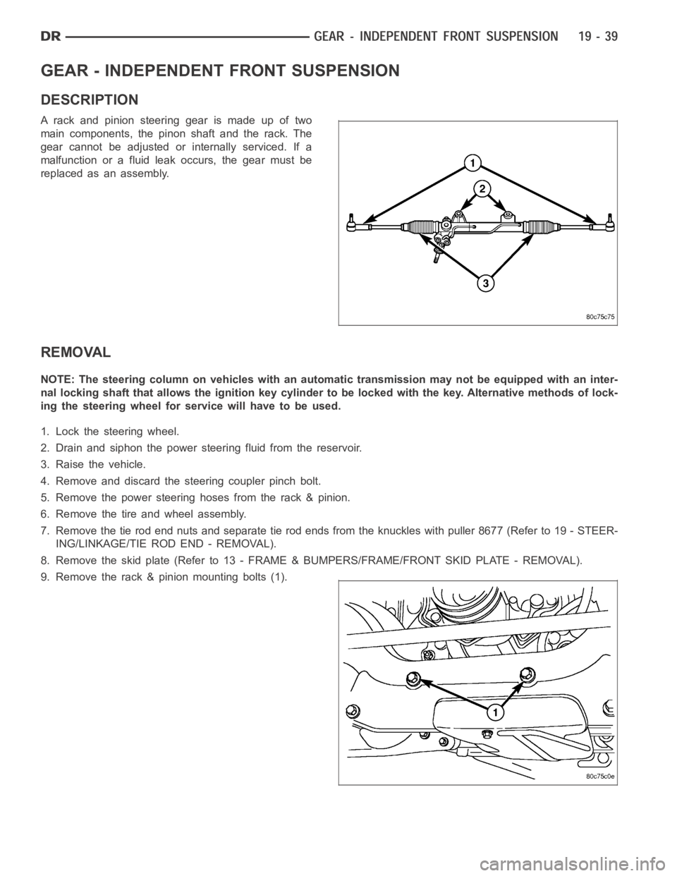
GEAR - INDEPENDENT FRONT SUSPENSION
DESCRIPTION
A rack and pinion steering gear is made up of two
main components, the pinon shaft and the rack. The
gear cannot be adjusted or internally serviced. If a
malfunction or a fluid leak occurs, the gear must be
replaced as an assembly.
REMOVAL
NOTE: The steering column on vehicles with an automatic transmission may not be equipped with an inter-
nal locking shaft that allows the ignition key cylinder to be locked with the key. Alternative methods of lock-
ing the steering wheel for service will have to be used.
1. Lock the steering wheel.
2. Drain and siphon the power steering fluid from the reservoir.
3. Raise the vehicle.
4. Remove and discard the steering coupler pinch bolt.
5. Remove the power steering hoses from the rack & pinion.
6. Remove the tire and wheel assembly.
7. Remove the tie rod end nuts and separate tie rod ends from the knuckles withpuller8677(Referto19-STEER-
ING/LINKAGE/TIE ROD END - REMOVAL).
8. Remove the skid plate (Refer to 13 - FRAME & BUMPERS/FRAME/FRONT SKID PLATE - REMOVAL).
9. Remove the rack & pinion mounting bolts (1).