2006 DODGE RAM SRT-10 check transmission fluid
[x] Cancel search: check transmission fluidPage 1971 of 5267
12. Install gear housing cover (Refer to 9 - ENGINE/VALVE TIMING/GEAR HOUSING COVER - INSTALLATION).
Install front crankshaft dust seal.
13. Install the crankshaft damper with the speed indicator ring (Refer to 9- ENGINE/ENGINE BLOCK/VIBRATION
DAMPER - INSTALLATION).
14. Install the fan support/hub assembly Refer to (Refer to 7 - COOLING/ENGINE/RADIATOR FAN - INSTALLA-
TION).
15. Install the power steering pump.
16. Install accessory drive belt tensioner. Torque bolt to 43 Nꞏm (32 ft. lbs.).
17. Install the accessory drive belt (Refer to 7 - COOLING/ACCESSORY DRIVE/DRIVE BELTS - INSTALLATION).
18. Install the charge air cooler (with a/c condenser and auxiliary transmission oil cooler, if equipped) and tighten
the mounting bolts to 2 Nꞏm (17 in. lbs.) torque.
19. Connect charge air cooler inlet and outlet pipes. Tighten clamps to 11 Nꞏm (95 in. lbs.) torque.
20. Install the radiator upper support panel.
21. Close radiator petcock and lower the radiator into the engine compartment. Tighten the mounting bolts to 11
Nꞏm (95 in. lbs.) torque.
22. Raise vehicle on hoist.
23. Connect radiator lower hose and install clamp.
24. Connect transmission auxiliary oil cooler lines (if equipped).
25. Lower vehicle.
26. Install the fandrive/shroud assembly. (Refer to 7 - COOLING/ENGINE/RADIATOR FAN - INSTALLATION)
27. Install the coolant recovery and windshield washer fluid reservoirs to the fan shroud.
28. Connect the coolant recovery hose to the radiator filler neck.
29. Add engine coolant (Refer to 7 - COOLING - STANDARD PROCEDURE).
30. Charge A/C system with refrigerant (if A/C equipped) (Refer to 24 - HEATING & AIR CONDITIONING/PLUMB-
ING - STANDARD PROCEDURE).
31. Connect the battery negative cables.
32. Start engine and check for engine oil and coolant leaks.
Page 2033 of 5267
5. Identify the fluid in the cylinder(s) (i.e., coolant, fuel, oil or other).
6. Make sure all fluid has been removed from the cylinders. Inspect engine for damage (i.e., connecting rods, pis-
tons, valves, etc.)
7. Repair engine or components as necessary to prevent this problem from re-occurring.
CAUTION: Squirt approximately one teaspoon of oil into the cylinders, rotateenginetolubricatethecylin-
der walls to prevent damage on restart.
8. Install new spark plugs.
9. Drain engine oil and remove oil filter.
10. Fill engine with specified amount of approved oil and install new oil filter.
11. Connect negative battery cable.
12. Start engine and check for any leaks.
REMOVAL - ENGINE ASSEMBLY
1. Perform fuel pressure release procedure (Refer to
14 - FUEL SYSTEM/FUEL DELIVERY - STAN-
DARD PROCEDURE).
2. Disconnect negative battery cable.
3. Disconnect throttle body air inlet duct, remove air
cleaner cover (Refer to 9 - ENGINE/AIR INTAKE
SYSTEM/AIR CLEANER ELEMENT - REMOVAL).
4. Raise and support the vehicle.
5. Remove the lower engine shield.
6. Drain cooling system (Refer to 7 - COOLING/EN-
GINE - STANDARD PROCEDURE - DRAINING
COOLING SYSTEM).
7. Paint mark and remove the driveshaft (Refer to 3 -
DIFFERENTIAL & DRIVELINE/PROPELLER
SHAFT/PROPELLER SHAFT - REMOVAL).
8.Removethetransmission(Referto21-TRANS-
MISSION/TRANSAXLE/MANUAL - REMOVAL).
9. Remove the starter (Refer to 8 - ELECTRICAL/
STARTING/STARTER MOTOR - REMOVAL).
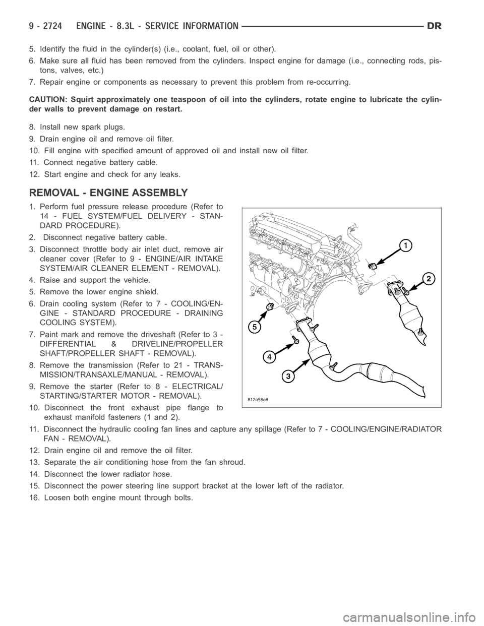
10. Disconnect the front exhaust pipe flange to
exhaust manifold fasteners (1 and 2).
11. Disconnect the hydraulic cooling fan lines and capture any spillage (Refer to 7 - COOLING/ENGINE/RADIATOR
FA N - R E M O VA L ) .
12. Drain engine oil and remove the oil filter.
13. Separate the air conditioning hose from the fan shroud.
14. Disconnect the lower radiator hose.
15. Disconnect the power steering line support bracket at the lower left ofthe radiator.
16. Loosen both engine mount through bolts.
Page 2407 of 5267
STEERING
DESCRIPTION
CAUTION: MOPARATF+4 is to be used in the power steering system. No other power steering or auto-
matic transmission fluid is to be used in the system. Damage may result to the power steering pump and
system if any other fluid is used, and do not overfill.
Power steering systems consist of:
Steering column
Rack and pinion steering gear
Belt driven hydraulic steering pump
Pump pressure and return hoses
Oil Cooler
OPERATION
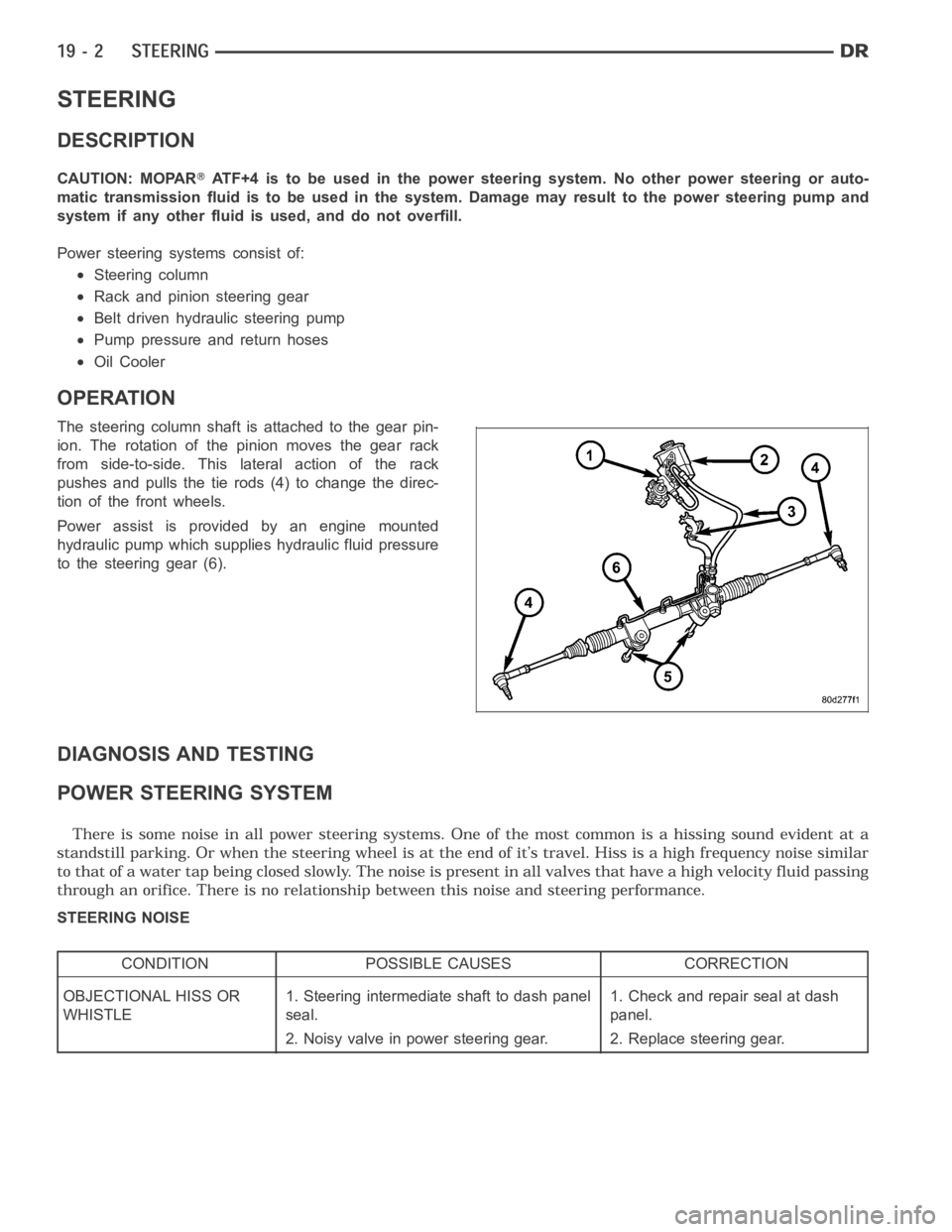
The steering column shaft isattached to the gear pin-
ion. The rotation of the pinion moves the gear rack
from side-to-side. This lateral action of the rack
pushes and pulls the tie rods (4) to change the direc-
tion of the front wheels.
Power assist is provided by an engine mounted
hydraulic pump which supplies hydraulic fluid pressure
to the steering gear (6).
DIAGNOSIS AND TESTING
POWER STEERING SYSTEM
STEERING NOISE
CONDITION POSSIBLE CAUSES CORRECTION
OBJECTIONAL HISS OR
WHISTLE1. Steering intermediate shaft to dash panel
seal.1. Check and repair seal at dash
panel.
2. Noisy valve in power steering gear. 2. Replace steering gear.
Page 2482 of 5267
PUMP
DESCRIPTION
CAUTION: MOPARATF+4 is to be used in the power steering system. No other power steering or auto-
matic transmission fluid is to be used in the system. Damage may result to the power steering pump and
system if any other fluid is used, and do not overfill.
The pump is connected to the steering gear via the pressure hose and the return hose. The pump shaft has a
pressed-on pulley that is belt driven by the crankshaft pulley.
All vehicles are equipped with a power steering fluid cooler.
NOTE: Power steering pumps are not interchangeable with pumps installed on other vehicles.
OPERATION
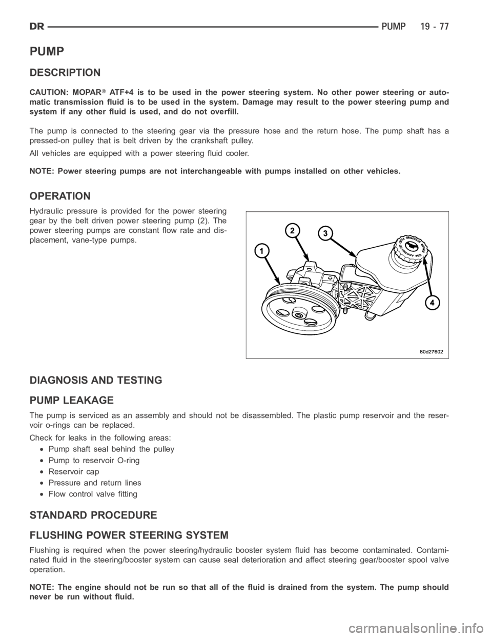
Hydraulic pressure is provided for the power steering
gear by the belt driven power steering pump (2). The
power steering pumps are constant flow rate and dis-
placement, vane-type pumps.
DIAGNOSIS AND TESTING
PUMP LEAKAGE
The pump is serviced as an assembly and should not be disassembled. The plastic pump reservoir and the reser-
voir o-rings can be replaced.
Check for leaks in the following areas:
Pump shaft seal behind the pulley
Pump to reservoir O-ring
Reservoir cap
Pressure and return lines
Flow control valve fitting
STANDARD PROCEDURE
FLUSHING POWER STEERING SYSTEM
Flushing is required when the power steering/hydraulic booster system fluid has become contaminated. Contami-
nated fluid in the steering/booster system can cause seal deterioration and affect steering gear/booster spool valve
operation.
NOTE: The engine should not be run so that all of the fluid is drained from thesystem. The pump should
never be run without fluid.
Page 2483 of 5267
1. Raise the front end of the vehicle off the ground until the wheels are freeto turn.
2. Remove the return line from the pump.
NOTE: If vehicle is equipped with a hydraulic booster remove both return lines from the pump.
3. Plug the return line port/ports at the pump.
4. Position the return line/lines into a large container to catch the fluid.
5. While an assistant is filling the pump reservoir start the engine.
6. With the engine running at idle turn the wheel back and forth.
NOTE: Do not contact or hold the wheel against the steering stops.
7. Run a quart of fluid through the system then stop the engine and install the return line/lines.
8. Fill the system with fluid and perform Steering Pump Initial Operation,(Refer to 19 - STEERING/PUMP - STAN-
DARD PROCEDURE).
9. Start the engine and run it for fifteen minutes then stop the engine.
10. Remove the return line/lines from the pump and plug the pump port/ports.
11. Pour fresh fluid into the reservoir and check the draining fluid for contamination. If the fluid is still contaminated,
then flush the system again.
12. Install the return line/lines and perform Steering Pump Initial Operation, (Refer to 19 - STEERING/PUMP -
STANDARD PROCEDURE).
POWER STEERING PUMP - INITIAL OPERATION
WARNING: THE FLUID LEVEL SHOULD BE CHECKED WITH ENGINE OFF TO PREVENT INJURYFROMMOV-
ING COMPONENTS.
CAUTION: MOPAR
ATF+4 is to be used in the power steering system. No other power steering or auto-
matic transmission fluid is to be used in the system. Damage may result to the power steering pump and
system if any other fluid is used, and do not overfill.
Wipe filler cap clean, then check the fluid level. The dipstick should indicateCOLDwhen the fluid is at normal
temperature.
1. Turn steering wheel all the way to the left.
2. Fill reservoir up to FULL HOT level and crank engine until it just starts.(DO NOT TURN STEERING WHEEL).
Then turn vehicle off. And recheck fluid level, to Full COLD.
3. Crank engine again until it just starts, (DO NOT MOVE STEERING WHEEL). and turn vehicle off. Recheck fluid
leveltoFullCOLD.
4. Turn engine on again, (DO NOT MOVE STEERING WHEEL) and let the vehicle idle for 5 minutes. If possible
apply a 20 in-Hg vacuum to the reservoir, while engine is idling.
5. Turn engine off and recheck fluid level, to FULL COLD.
6.If the Steering gear is replacedensure reservoir is at FULL HOT level, start engine and turn wheel to left. Stop
Engine and recheck fluid level to FULL HOT. Start engine and turn wheel to the right. Stop engine and check
fluid level is at FULL COLD.
7. Fill the pump fluid reservoir to the proper level and let the fluid settlefor at least two (2) minutes.
8. Start the engine. With the engine idling maintain the fluid level.
9. Raise the front wheels off the ground.
10. Slowly turn the steering wheel lock-to-lock 20 times with the engine off while checking the fluid level.
NOTE: For vehicles with long return lines or oil coolers turn wheel 40 times.
11. Lower the front wheels and let the engine idle for two minutes.
12. Turn the steering wheel in both direction and verify power assist and quiet operation of the pump.
If the fluid is extremely foamy or milky looking, allow the vehicle to standa few minutes and repeat the procedure.
Page 2487 of 5267
FLUID
DESCRIPTION
NOTE: It is normal that some pressure will build up inside the reservoir, especially, with a warm vehicle. A
slight popping noise upon removal ofthe cap is normal. The fluid level should read between the ADD and
the FULL COLD marks. When the fluid is hotit should read between ADD and FULLHOT marks. Only add
fluid when the vehicle is cold.
The recommended fluid for the power steering system is Mopar
AT F + 4 .
Mopar
ATF+4, when new is red in color. The ATF+4 is dyed red so it can be identified from other fluids used in the
vehicle such as engine oil or antifreeze. The red color is not permanent andis not an indicator of fluid condition, As
the vehicle is driven, the ATF+4 will begin to look darker in color and may eventually become brown.THIS IS NOR-
MAL.ATF+4 also has a unique odor that may change with age. Consequently, odor and color cannot be used to
indicate the fluid condition or the need for a fluid change.
STANDARD PROCEDURE
POWER STEERING FLUID LEVEL CHECKING
WARNING: FLUID LEVEL SHOULD BE CHECKED WITH THE ENGINE OFF TO PREVENT PERSONAL INJURY
FROM MOVING PARTS.
CAUTION: MOPAR
ATF+4 is to be used in the power steering system. No other power steering or auto-
matic transmission fluid is to be used in the system. Damage may result to the power steering pump and
system if any other fluid is used, and do not overfill.
The power steering fluid level can be viewed on the dipstick attached to thefiller cap. There are two ranges listed
on the dipstick, COLD and HOT. Before opening power steering system, wipe the reservoir filler cap free of dirt and
debris. Remove the cap and check the fluid level on its dipstick. When the fluid is at normal ambient temperature,
approximately 21°C to 27°C (70°F to 80°F), the fluid level should read between the minimum and maximum area of
the cold range. When the fluid is hot, fluid level is allowed to read up to thehighest end of the HOT range. Only add
fluid when the vehicle is cold.
Use only Mopar
AT F + 4 .Do not overfill the power steering system.
Page 2500 of 5267
STANDARD PROCEDURE
INITIAL OPERATION
WARNING: The fluid level should be checked with engine off to prevent injury from moving components.
NOTE: Remove as much of the old fluid out of the system as possible with a suction tool or by removing
a hose, when a component has failed. Then refill it with fresh fluid until itis clean. This may have to be
done more than once.
CAUTION: MOPAR
ATF+4 is to be used in the power steering system. No other power steering or auto-
matic transmission fluid is to be used in the system. Damage may result to the power steering pump and
system if any other fluid is used, and do not overfill.
Wipe filler cap clean, then check the fluid level. The dipstick should indicateCOLDwhen the fluid is at normal
ambient temperature.
1. Fill the pump fluid reservoir to the proper level and let the fluid settlefor at least two minutes.
2. Start the engine and let run for a few seconds then turn engine off.
3. Add fluid if necessary. Repeat the above procedure until the fluid levelremains constant after running the engine.
4. Raise the front wheels off the ground.
5. Slowly turn the steering wheel right and left, lightly contacting the wheel stops at least 20 times.
6. Check the fluid level add if necessary.
7. Lower the vehicle, start the engine, and use the DRB III to activate the hydraulic fan on full fan operation.
8. Turn the steering wheel slowly from lock to lock.
9. Stop the engine, check the fluid level and refill as required and repeat the process
CAUTION: Do not run a vehicle with foamy fluid for an extended period. This may cause pump damage.
10. If the fluid is extremely foamy or milky looking, allow the vehicle to stand a few minutes and repeat the pro-
cedure.
11. While the vehicle is in park, use the DRB III to activate the hydraulic fan to full fan operation and briefly rev the
engine up to 3000 rpm to fully engage the hydraulic fan.
12. Check the fluid level add if necessary.
Page 2592 of 5267
MANUAL TRANSMISSION - GETRAG 238 - SERVICE INFORMATION
DIAGNOSIS AND TESTING
MANUAL TRANSMISSION - GETRAG 238
LOW LUBRICANT LEVEL
A low transmission lubricant level is generally the result of a leak, inadequate lubricant fill or incorrect lubricant level
check.
Rear transmission leakswill be from the oil seals or transfer case front seal on 4x4.
Front transmission leakswill be from the front input shaft retainer seal. Lubricant may drip from theclutchhousing
after extended operation. If leak is severe, it may contaminate the clutchdisc.
Lubricant level checkcan only be made when the vehicle is level and allowing the lubricant to settle for a minute
before checking. This will ensure an accurate check and avoid an under or overfill condition.
HARD SHIFTING
Hard shifting can be caused by low lubricant level, improper or contaminated lubricants. This will cause noise,
excessive wear, internal bind, and hard shifting. Substantial lubricantleaks can result in gear, shift rail, synchro, and
bearing damage. The first indications of component damage is usually hardshifting and noise.
Shift component damage, clutch adjustment, worn pressure plate or disc, can increased shift effort. If clutch problem
is advanced, gear clash during shifts can result. Worn or damaged synchronizer rings can cause gear clash when
shifting into any forward gear. In some new or rebuilt transmissions, new synchro rings may tend to stick slightly
causing hard or noisy shifts. In most cases, this condition will decline asthe rings wear-in.
TRANSMISSION NOISE
Most manual transmissions make some noise during normal operation. Rotating gears generate a mild whine that is
audible, but generally only at extreme speeds.
Severe, highly audible transmission noise is generally the initial indicator of a lubricant problem. Insufficient,
improper or contaminated lubricant will promote rapid wear of gears, synchronizer rings, shift rails, forks and bear-
ings. The overheating caused by a lubricant problem, can also lead to gear and bearing damage.
STANDARD PROCEDURE
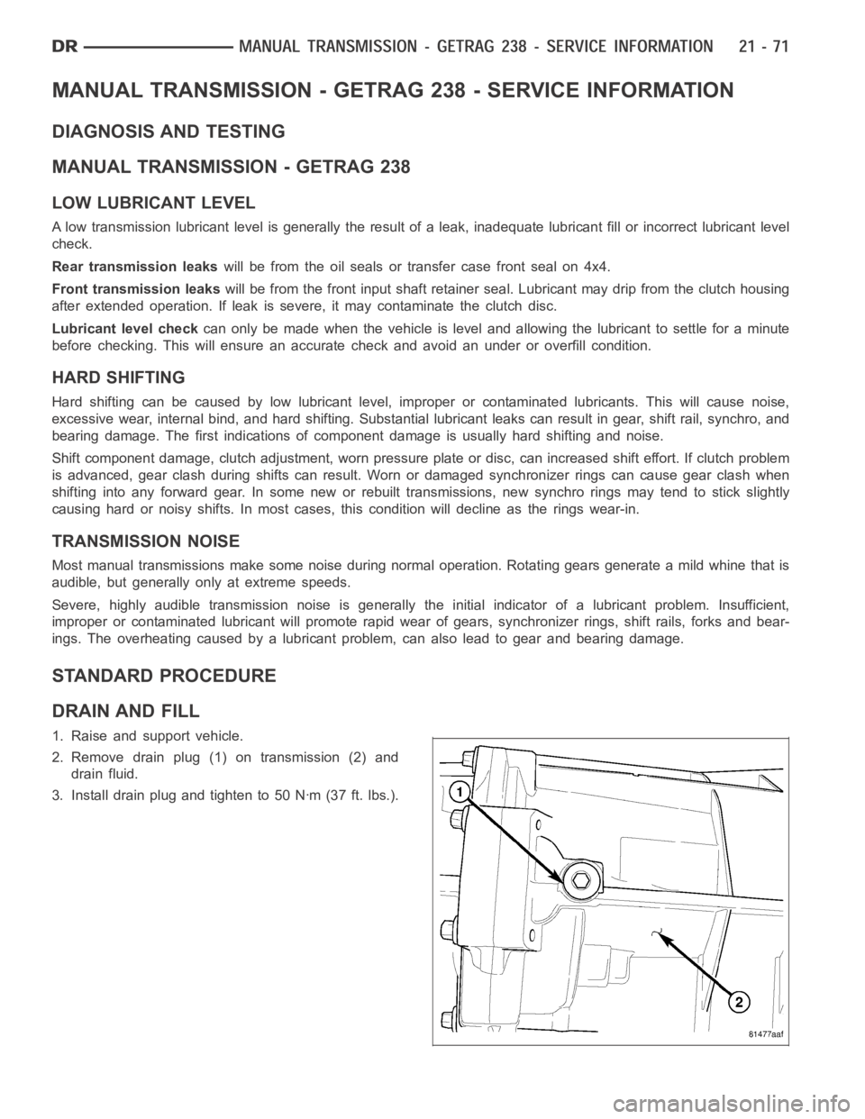
DRAIN AND FILL
1. Raise and support vehicle.
2. Remove drain plug (1) on transmission (2) and
drain fluid.
3. Install drain plug and tighten to 50 Nꞏm (37 ft. lbs.).