2006 DODGE RAM SRT-10 check transmission fluid
[x] Cancel search: check transmission fluidPage 2833 of 5267
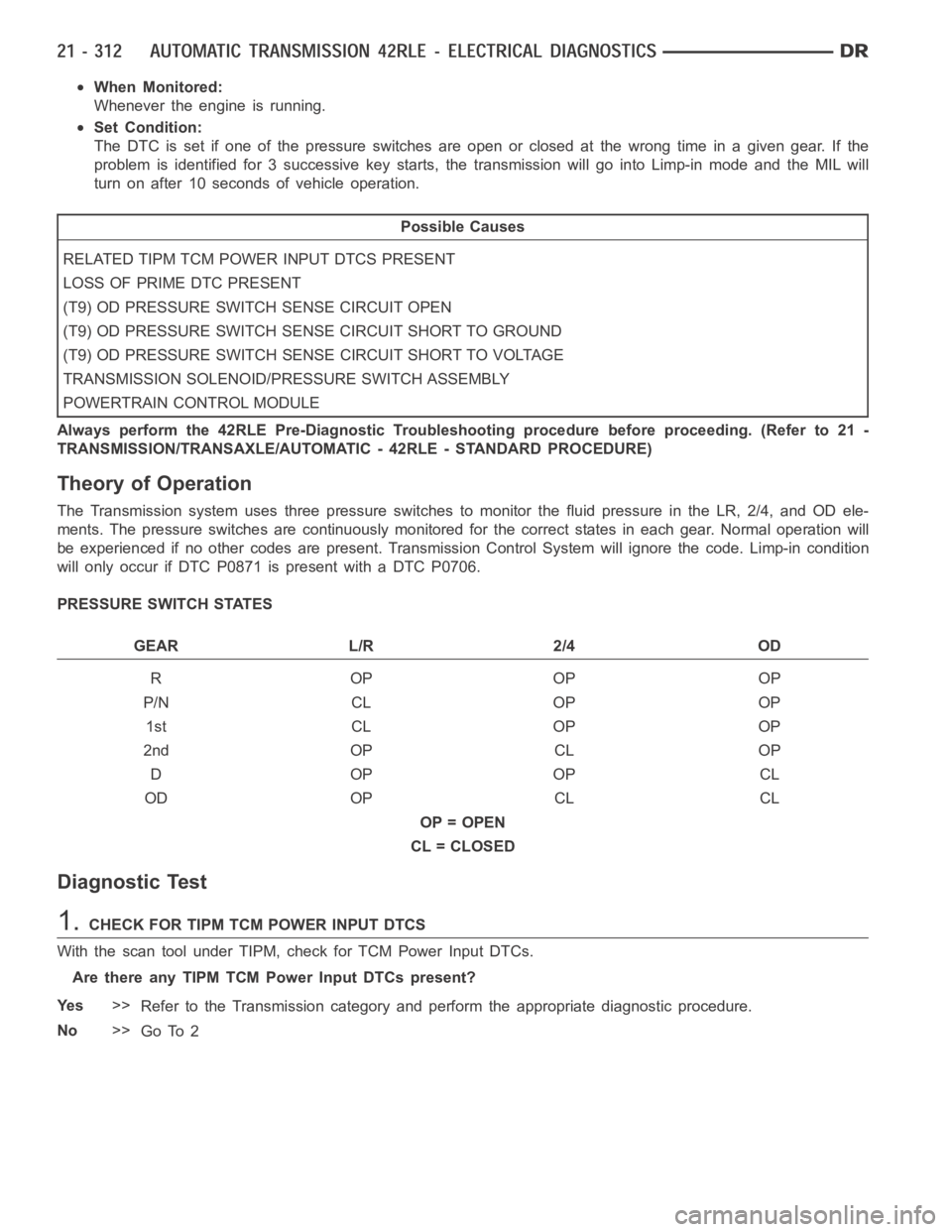
When Monitored:
Whenever the engine is running.
Set Condition:
The DTC is set if one of the pressure switches are open or closed at the wrong time in a given gear. If the
problem is identified for 3 successive key starts, the transmission will go into Limp-in mode and the MIL will
turn on after 10 seconds of vehicle operation.
Possible Causes
RELATED TIPM TCM POWER INPUT DTCS PRESENT
LOSS OF PRIME DTC PRESENT
(T9) OD PRESSURE SWITCH SENSE CIRCUIT OPEN
(T9) OD PRESSURE SWITCH SENSE CIRCUIT SHORT TO GROUND
(T9) OD PRESSURE SWITCH SENSE CIRCUIT SHORT TO VOLTAGE
TRANSMISSION SOLENOID/PRESSURE SWITCH ASSEMBLY
POWERTRAIN CONTROL MODULE
Always perform the 42RLE Pre-Diagnostic Troubleshooting procedure before proceeding. (Refer to 21 -
TRANSMISSION/TRANSAXLE/AUTOMATIC - 42RLE - STANDARD PROCEDURE)
Theory of Operation
The Transmission system uses three pressure switches to monitor the fluidpressure in the LR, 2/4, and OD ele-
ments. The pressure switches are continuously monitored for the correct states in each gear. Normal operation will
be experienced if no other codes are present. Transmission Control Systemwill ignore the code. Limp-in condition
will only occur if DTC P0871 is present with a DTC P0706.
PRESSURE SWITCH STATES
GEAR L/R 2/4 OD
ROPOPOP
P/N CL OP OP
1st CL OP OP
2nd OP CL OP
DOPOPCL
OD OP CL CL
OP = OPEN
CL = CLOSED
Diagnostic Test
1.CHECK FOR TIPM TCM POWER INPUT DTCS
With the scan tool under TIPM, check for TCM Power Input DTCs.
Are there any TIPM TCM Power Input DTCs present?
Ye s>>
Refer to the Transmission category and perform the appropriate diagnostic procedure.
No>>
Go To 2
Page 2864 of 5267
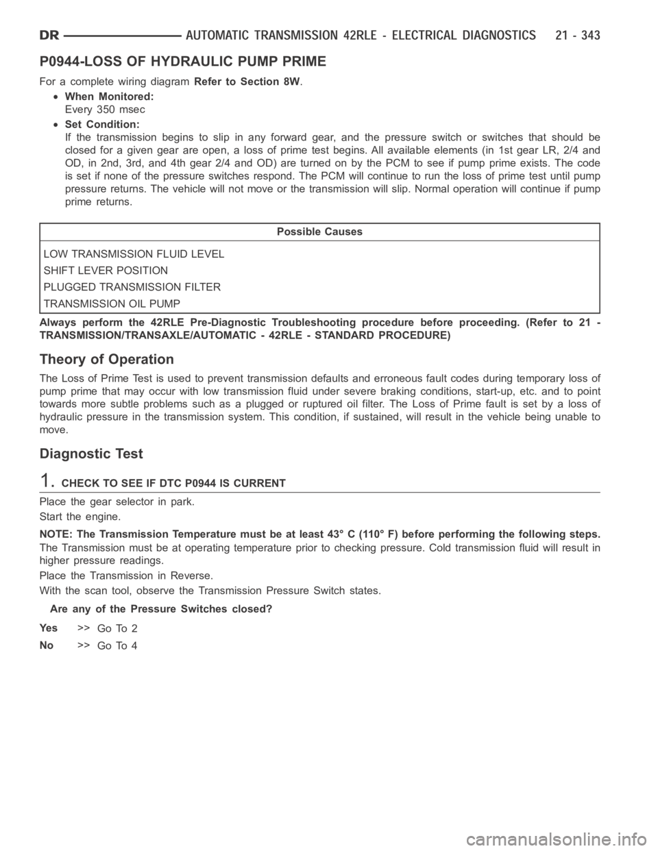
P0944-LOSS OF HYDRAULIC PUMP PRIME
For a complete wiring diagramRefer to Section 8W.
When Monitored:
Every 350 msec
Set Condition:
If the transmission begins to slip in any forward gear, and the pressure switch or switches that should be
closed for a given gear are open, a loss of prime test begins. All available elements (in 1st gear LR, 2/4 and
OD, in 2nd, 3rd, and 4th gear 2/4 and OD) are turned on by the PCM to see if pump prime exists. The code
is set if none of the pressure switches respond. The PCM will continue to runthe loss of prime test until pump
pressure returns. The vehicle will not move or the transmission will slip.Normal operation will continue if pump
prime returns.
Possible Causes
LOW TRANSMISSION FLUID LEVEL
SHIFT LEVER POSITION
PLUGGED TRANSMISSION FILTER
TRANSMISSION OIL PUMP
Always perform the 42RLE Pre-Diagnostic Troubleshooting procedure before proceeding. (Refer to 21 -
TRANSMISSION/TRANSAXLE/AUTOMATIC - 42RLE - STANDARD PROCEDURE)
Theory of Operation
The Loss of Prime Test is used to prevent transmission defaults and erroneous fault codes during temporary loss of
pump prime that may occur with low transmission fluid under severe brakingconditions, start-up, etc. and to point
towards more subtle problems such as a plugged or ruptured oil filter. The Loss of Prime fault is set by a loss of
hydraulic pressure in the transmission system. This condition, if sustained, will result in the vehicle being unable to
move.
Diagnostic Test
1.CHECK TO SEE IF DTC P0944 IS CURRENT
Place the gear selector in park.
Start the engine.
NOTE: The Transmission Temperature must be at least 43° C (110° F) before performing the following steps.
The Transmission must be at operating temperature prior to checking pressure. Cold transmission fluid will result in
higher pressure readings.
Place the Transmission in Reverse.
With the scan tool, observe the Transmission Pressure Switch states.
Are any of the Pressure Switches closed?
Ye s>>
Go To 2
No>>
Go To 4
Page 2865 of 5267
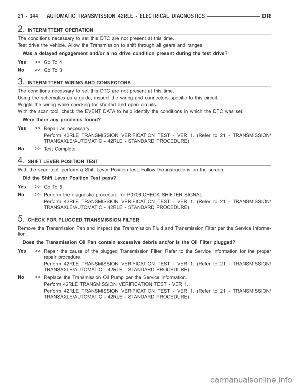
2.INTERMITTENT OPERATION
The conditions necessary to set this DTC are not present at this time.
Test drive the vehicle. Allow the Transmission to shift through all gears and ranges.
Was a delayed engagement and/or a no drive condition present during the testdrive?
Ye s>>
Go To 4
No>>
Go To 3
3.INTERMITTENT WIRING AND CONNECTORS
The conditions necessary to set this DTC are not present at this time.
Using the schematics as a guide, inspect the wiring and connectors specifictothiscircuit.
Wiggle the wiring while checking for shorted and open circuits.
With the scan tool, check the EVENT DATAto help identify the conditions in which the DTC was set.
Were there any problems found?
Ye s>>
Repair as necessary.
Perform 42RLE TRANSMISSION VERIFICATION TEST - VER 1. (Refer to 21 - TRANSMISSION/
TRANSAXLE/AUTOMATIC - 42RLE - STANDARD PROCEDURE)
No>>
Te s t C o m p l e t e .
4.SHIFT LEVER POSITION TEST
With the scan tool, perform a Shift Lever Position test. Follow the instructions on the screen.
Did the Shift Lever Position Test pass?
Ye s>>
Go To 5
No>>
Perform the diagnostic procedure for P0706-CHECK SHIFTER SIGNAL.
Perform 42RLE TRANSMISSION VERIFICATION TEST - VER 1. (Refer to 21 - TRANSMISSION/
TRANSAXLE/AUTOMATIC - 42RLE - STANDARD PROCEDURE)
5.CHECK FOR PLUGGED TRANSMISSION FILTER
Remove the Transmission Pan and inspect the Transmission Fluid and Transmission Filter per the Service Informa-
tion.
Does the Transmission Oil Pan contain excessive debris and/or is the Oil Filter plugged?
Ye s>>
Repair the cause of the plugged Transmission Filter. Refer to the Service Information for the proper
repair procedure.
Perform 42RLE TRANSMISSION VERIFICATION TEST - VER 1. (Refer to 21 - TRANSMISSION/
TRANSAXLE/AUTOMATIC - 42RLE - STANDARD PROCEDURE)
No>>
Replace the Transmission Oil Pump per the Service Information.
Perform 42RLE TRANSMISSION VERIFICATION TEST - VER 1.
Perform 42RLE TRANSMISSION VERIFICATION TEST - VER 1. (Refer to 21 - TRANSMISSION/
TRANSAXLE/AUTOMATIC - 42RLE - STANDARD PROCEDURE)
Page 2886 of 5267
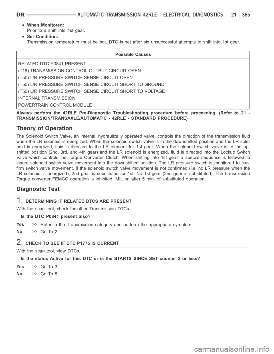
When Monitored:
Prior to a shift into 1st gear.
Set Condition:
Transmission temperature must be hot. DTC is set after six unsuccessful attempts to shift into 1st gear.
Possible Causes
RELATED DTC P0841 PRESENT
(T16) TRANSMISSION CONTROL OUTPUT CIRCUIT OPEN
(T50) L/R PRESSURE SWITCH SENSE CIRCUIT OPEN
(T50) L/R PRESSURE SWITCH SENSE CIRCUIT SHORT TO GROUND
(T50) L/R PRESSURE SWITCH SENSE CIRCUIT SHORT TO VOLTAGE
INTERNAL TRANSMISSION
POWERTRAIN CONTROL MODULE
Always perform the 42RLE Pre-Diagnostic Troubleshooting procedure before proceeding. (Refer to 21 -
TRANSMISSION/TRANSAXLE/AUTOMATIC - 42RLE - STANDARD PROCEDURE)
Theory of Operation
The Solenoid Switch Valve, an internal, hydraulically operated valve, controls the direction of the transmission fluid
when the LR solenoid is energized. When the solenoid switch valve is in the downshifted position and the LR sole-
noid is energized, fluid is directed to the LR element for 1st gear. When thesolenoid switch valve is In the up-
shifted position (2nd, 3rd, and 4th gear) and the LR solenoid is energized,fluidisdirectedintotheLockupSwitch
Valve which controls the Torque Converter Clutch. When shifting into 1st gear, a special sequence is followed to
insure solenoid switch valve movement into the downshifted position. TheLR pressure switch is monitored to con-
firm switch valve movement. If the solenoid switch valve movement is not confirmed (i.e. no LR pressure when the
LR solenoid is energized), 2nd gear is substituted for 1st. No 1st gear (2ndgear is substituted). The transmission
Torque converter FEMCC operation is inhibited. MIL on after 5 min. of substituted operation.
Diagnostic Test
1.DETERMINING IF RELATED DTCS ARE PRESENT
With the scan tool, check for other Transmission DTCs
Is the DTC P0841 present also?
Ye s>>
Refer to the Transmission category and perform the appropriate symptom.
No>>
Go To 2
2.CHECK TO SEE IF DTC P1775 IS CURRENT
With the scan tool, view DTCs.
Is the status Active for this DTC or is the STARTS SINCE SET counter 2 or less?
Ye s>>
Go To 3
No>>
Go To 8
Page 2891 of 5267
When Monitored:
Every 7 ms when doing PEMCC or FEMCC.
Set Condition:
Must be in partial or full EMCC. The DTC is set if L/R pressure is detected high for the fourth time.
Possible Causes
RELATED DTC P0841 PRESENT
DTC EVENT DATA SHOWS TRS CODE TR2 - SHIFT LEVER OR MANUAL CONTROL VALVE IN A INVA L I D
POSITION
SHIFTER CABLE OUT OF ADJUSTMENT
SOLENOID SWITCH VALVE STICKING IN ITS BORE
(T50) L/R PRESSURE SWITCH SENSE CIRCUIT OPEN
(T50) L/R PRESSURE SWITCH SENSE CIRCUIT SHORT TO GROUND
(T50) L/R PRESSURE SWITCH SENSE CIRCUIT SHORT TO VOLTAGE
VA LV E B O D Y
POWERTRAIN CONTROL MODULE
Always perform the Pre-Diagnostic Troubleshooting procedure before proceeding. (Refer to 21 - TRANSMIS-
SION/TRANSAXLE/AUTOMATIC - 42RLE - STANDARD PROCEDURE)
Theory of Operation
The Solenoid Switch Valve, an internal, hydraulically operated valve, controls the direction of the transmission fluid
when the L/R solenoid is energized. When the solenoid switch valve is in thedownshifted position and the L/R
solenoid is energized, fluid is directed to the L/R element for 1st gear. When the solenoid switch valve is In the
up-shifted position (2nd, 3rd, and 4th gear) and the L/R solenoid is energized, fluid is directed into the Lockup
Switch Valve which controls the Torque Converter Clutch. When doing PEMCCor FEMCC, the L/R pressure switch
should indicate no pressure if the solenoid switch valve is in the L/R position. If the L/R pressure switch indicates
pressure for some time while in partial or full EMCC, the EMCC operation is aborted and momentarily inhibited to
avoid accidental application of the L/R clutch. EMCC is attempted again when there is no L/R pressure. The fourth
detection of L/R pressure while in PEMCC or FEMCC will result in setting theDTC. Torque converter EMCC oper-
ation inhibited. MIL on after 5 min. of substituted operation.
Diagnostic Test
1.DETERMINING IF RELATED DTC’S ARE PRESENT
With the scan tool, check for other Transmission DTC’s
Is the DTC P0841 present also?
Ye s>>
Refer to the Transmission category and perform the appropriate symptom.
No>>
Go To 2
2.CHECK THE DTC EVENT DATA FOR TRS CODE TR2
With the scan tool, check the DTC EVENT DATA for P1776.
Does the DTC EVENT DATA show a TRS Code of TR2?
Ye s>>
This indicates the shift lever and the manual control valve were in an invalid position between Neutral
and OD. Check the shifter cable for: proper adjustment, binding, friction, improper routing, or the shifter
was moved in transit. Repair as necessary.
Perform 42RLE TRANSMISSION VERIFICATION TEST - VER 1. (Refer to 21 - TRANSMISSION/
TRANSAXLE/AUTOMATIC - 42RLE - STANDARD PROCEDURE)
No>>
Go To 3
Page 2899 of 5267
P1797-MANUAL SHIFT OVERHEAT
For a complete wiring diagramRefer to Section 8W.
When Monitored:
Continuously with engine running.
Set Condition:
If the Engine Temperature exceeds 123° C (255° F) or the Transmission Temperature exceeds 135° C (275° F)
while in AutoStick
mode. Note: Aggressive driving or driving in low for extended periods of time will set this
DTC.
Possible Causes
MANUAL SHIFT OVERHEAT
Always perform the 42RLE Pre-Diagnostic Troubleshooting procedure before proceeding. (Refer to 21 -
TRANSMISSION/TRANSAXLE/AUTOMATIC - 42RLE - STANDARD PROCEDURE)
Theory of Operation
The major cause of heat build up in the transmission is torque converter slip.WiththetransmissionintheAuto-
Stick
mode, the torque converter can slip during aggressive driving or heavy loading conditions such as trailer
towing or driving up steep grades. In the non AutoStick
mode, internal controller logic prevents the transmission
from overheating by managing the shift and EMCC schedule. In the AutoStick
mode, when the transmission or
engine temperature approaches an overheat condition, the manual shift overheat DTC sets and the AutoStick
mode is temporarily suspended until the temperature returns to normal.
Diagnostic Test
1.MANUAL SHIFT OVERHEAT
This is an informational DTC only.
With the scan tool, check the DTC EVENT DATA to help identify the conditionsin which the DTC was set.
Check the engine and transmission cooling system for proper operation.
Check the Radiator Cooling Fan operation.
Check the Transmission Cooling operation.
Check the Transmission Fluid Level per the Service Information to verify that it is not overfilled.
NOTE: Aggressive driving or driving in low for extended periods of time will set this DTC.
If there are no possible causes remaining, view repair.
Repair
If the Transmission Fluid is low, repair any Transmission Fluid leak as necessary and adjust the Trans-
mission Fluid Level per the Service Information. Refer to Service Information for the related symptoms
and repair as necessary.
Perform 42RLE TRANSMISSION VERIFICATION TEST - VER 1. (Refer to 21 - TRANSMISSION/
TRANSAXLE/AUTOMATIC - 42RLE - STANDARD PROCEDURE)
Page 2908 of 5267
STANDARD PROCEDURE
PRE-DIAGNOSTIC TROUBLESHOOTING PROCEDURE - 42RLE
For a complete wiring diagramRefer to Section 8W.
1.
Perform the following steps prior to any diagnostic procedure:
Many transmission symptoms can be caused by a low fluid level. If the fluid level is low, locate and repair any
leaks and fill the transmission to the proper fluid level. Refer to the Service Information for the proper repair
and fluid fill procedures.
Testing should only be performed with the battery fully charged to avoid false diagnosis.
With the scan tool, read Engine (PCM) DTCs. If Engine DTCs are present, refer to the Driveability Category
and perform to the appropriate diagnostic procedure(s) before proceeding.
With the scan tool, read Transmission (TCM) DTCs. Record all Stored, Active, and Pending DTC information.
Diagnose any Pending DTC as a matured DTC.
With the scan tool, read DTC EVENT DATA.Use this data to identify the conditions in which the DTC was set.
Note: Performing a Battery Disconnect will clear all DTC EVENT DATA and reset all learned Transmis-
sion values to the controllers default values, which may temporarily result in erratic shift schedules.
With the scan tool, perform the Shift Lever Position Test. If the test does not pass, refer to the diagnostic
procedure for P0706-Check Shifter Signal.
For Gear Ratio Error DTCs, use the scan tool to read and record the Clutch Volume Index (CVI) information.
Use the wiring diagram as a guide, inspect the wiring and connectors related to this circuit and repair as nec-
essary.
Refer to the When Monitored and Set Conditions for this DTC. DTCs can set at ignition on, at start up, driving
under specific conditions, and after controller diagnostic monitors haverun.
Refer to applicable Technical Service Bulletins (TSBs) for controller software update information. Some condi-
tions can be corrected by upgrading the Engine (PCM) or Transmission (TCM)controller software.
Check for any Service Information Tune-ups or Service Bulletins for any possible causes that may apply.
Were there any repairs made that fixed the vehicle?
Ye s>>
Testing complete.
Perform 42RLE VERIFICATION TEST - VER1(Referto21-TRANSMISSION/TRANSAXLE/AUTO-
MATIC - 42RLE - STANDARD PROCEDURE)
No>>
Refer to the Transmission category and perform the appropriate diagnostic procedure(s). (Refer to 21 -
TRANSMISSION/TRANSAXLE/AUTOMATIC - 42RLE - DIAGNOSIS AND TESTING)
Page 2909 of 5267
42RLE TRANSMISSION VERIFICATION TEST - VER 1
1.
Perform the following after completion of a diagnostic repair:
Note: After completion of the Transmission Verification Test, the Powertrain Verification Test must be
performed. Refer to the Engine Category.
Reconnect any disconnected components.
With the scan tool, erase all Transmission and Engine DTCs.
Erase DTC P0700 under engine to turn off the MIL off after completion of transmission repairs.
Perform *PRNDL FAULT CLEARING PROCEDURE after completion of repairs for P0706-TRANSMISSION
RANGE SENSOR RATIONALITY.
If the Powertrain Control Module or the Transmission has been repaired or replaced, it is necessary to perform
the scan tool Quick Learn Procedure.
If the Torque converter has been replaced, with the scan tool perform TCC BREAK-IN.
If the Powertrain Control Module or Front Control Module has been replacedyoumustresetthePinionFactor
in the Front Control Module.
With the scan tool, display Transmission Temperature. Start and run the engine until the Transmission Tem-
perature is HOT, above 43° C or 110° F.
Check the transmission fluid and adjust if necessary. Refer to the ServiceInformation for the Fluid Fill proce-
dure.
Road test the vehicle. With the scan tool, monitor the engine RPM. Make 15 to20 1-2, 2-3, 3-4 upshifts.
Perform these shifts from a standing start to 45 mph with a constant throttleopeningof20to25degrees.
With speeds below 25 MPH, make 5 to 8 wide open throttle kickdowns to 1st gear. Allow at least 5 seconds
each in 2nd and 3rd gear between each kickdown.
For a specific DTC, drive the vehicle to the Symptom’s When Monitored/WhenSet conditions to verify the DTC
is repaired.
If equipped with AutoStick, upshift and downshift several times using the AutoStickfeature during the road
test.
Note: Use the OBDII task manager to run a Good Trip in each gear, this will confirm the repair and to
ensure that the DTC has not re-matured.
Check for any Diagnostic Trouble Codes (DTCs) during and after the road test.
Did any Diagnostic Trouble Codes set during the road test?
Ye s>>
Repair is not complete. Refer to the Transmission category and perform theappropriate symptom(s).
(Refer to 21 - TRANSMISSION/TRANSAXLE/AUTOMATIC - 42RLE - DIAGNOSIS AND TESTING)
No>>
Repair is complete.