2006 DODGE RAM SRT-10 washer fluid
[x] Cancel search: washer fluidPage 1776 of 5267
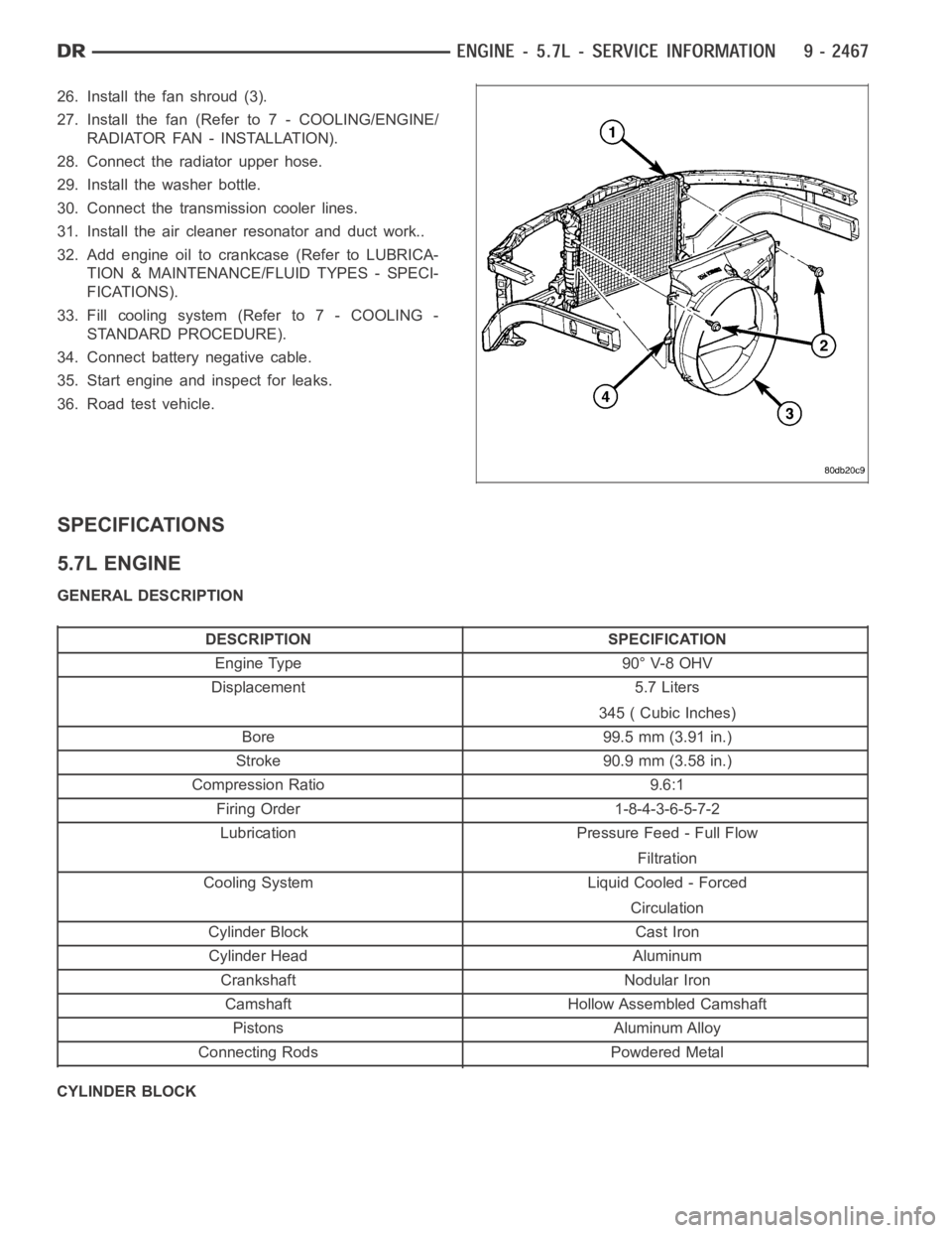
26. Install the fan shroud (3).
27. Install the fan (Refer to 7 - COOLING/ENGINE/
RADIATOR FAN - INSTALLATION).
28. Connect the radiator upper hose.
29. Install the washer bottle.
30. Connect the transmission cooler lines.
31. Install the air cleaner resonator and duct work..
32. Add engine oil to crankcase (Refer to LUBRICA-
TION & MAINTENANCE/FLUID TYPES - SPECI-
FICATIONS).
33. Fill cooling system (Refer to 7 - COOLING -
STANDARD PROCEDURE).
34. Connect battery negative cable.
35. Start engine and inspect for leaks.
36. Road test vehicle.
SPECIFICATIONS
5.7L ENGINE
GENERAL DESCRIPTION
DESCRIPTION SPECIFICATION
Engine Type 90° V-8 OHV
Displacement 5.7 Liters
345 ( Cubic Inches)
Bore 99.5 mm (3.91 in.)
Stroke 90.9 mm (3.58 in.)
Compression Ratio 9.6:1
Firing Order 1-8-4-3-6-5-7-2
Lubrication Pressure Feed - Full Flow
Filtration
Cooling System Liquid Cooled - Forced
Circulation
Cylinder Block Cast Iron
Cylinder Head Aluminum
Crankshaft Nodular Iron
Camshaft Hollow Assembled Camshaft
Pistons Aluminum Alloy
Connecting Rods Powdered Metal
CYLINDER BLOCK
Page 1912 of 5267
12. Place a rag over the compression test tool fitting. Crank the engine for2–3 seconds to purge any fuel that may
have drained into the cylinder when the injector was removed.
13. Connect the compression test gauge.
14. Crank the engine for 5 seconds and record the pressure reading. Repeat this step three times and calculate the
average of the three readings.
NOTE: The minimum cylinder pressure is 350 psi. Cylinder pressure should be within 20% from cylinder to
cylinder.
15. Combustion pressure leakage can be checked if cylinder pressure is below the specification. Perform the leak-
age test procedure on each cylinder according to the tester manufacturer instructions.
16. Upon completion of the test check and erase any engine related fault codes.
CYLINDER COMBUSTION PRESSURE LEAKAGE
The combustion pressure leakage test provides an accurate means for determining engine condition.
Combustion pressure leakage testing will detect:
Exhaust and intake valve leaks (improper seating).
Leaks between adjacent cylinders or into water jacket.
Any causes for combustion/compression pressure loss
1. Start and operate the engine until it attains normal operating temperature.
2. Disconnect injector harness connectors.
3. Disconnect breather tube and breather drain tube from valve cover.
4. Remove the cylinder head cover. (Refer to 9 - ENGINE/CYLINDER HEAD/CYLINDER HEAD COVER(S) -
REMOVAL)
5. Disconnect harness from injectors.
6. Remove the cylinder head cover carrier gasket. (Refer to 9 - ENGINE/CYLINDER HEAD/CYLINDER HEAD
COVER(S) - REMOVAL)
7. BringthecylindertobetestedtoTDC.
8. Remove the high pressure fuel line between the cylinder head and the fuelrail for the cylinder to be tested.
9. Install capping Tool 9011 onto the rail.
10. Remove the high pressure connector nut and high pressure connector with Tool 9015.
11. Remove the exhaust and intake rocker lever.
12. Use Tool # 9010 to remove the injector and copper sealing washer.
13. Install compression test Tool # 9007 into the injector bore.
14. Connect the leakage tester and perform the leakage test procedure on each cylinder according to the tester
manufacturer’s instructions.
15. Upon completion of the test check and erase any engine related fault codes.
STANDARD PROCEDURE
STANDARD PROCEDURE - FORM-IN-PLACE GASKETS AND SEALERS
There are numerous places where form-in-place gaskets are used on the engine. Care must be taken when apply-
ing form-in-place gaskets to assure obtaining the desired results.Do not use form-in-place gasket material
unless specified.Bead size, continuity, and location are of great importance. Too thin a bead can result in leakage
while too much can result in spill-overwhich can break off and obstruct fluid feed lines. A continuous bead of the
proper width is essential to obtain a leak-free gasket.
There are numerous types of form-in-place gasket materials that are used in the engine area. Mopar
Engine RTV
GEN II, Mopar
ATF-RTV, and MoparGasket Maker gasket materials, each have different properties and can not
be used in place of the other.
MOPAR
ENGINE RTV GEN II
Page 1971 of 5267
12. Install gear housing cover (Refer to 9 - ENGINE/VALVE TIMING/GEAR HOUSING COVER - INSTALLATION).
Install front crankshaft dust seal.
13. Install the crankshaft damper with the speed indicator ring (Refer to 9- ENGINE/ENGINE BLOCK/VIBRATION
DAMPER - INSTALLATION).
14. Install the fan support/hub assembly Refer to (Refer to 7 - COOLING/ENGINE/RADIATOR FAN - INSTALLA-
TION).
15. Install the power steering pump.
16. Install accessory drive belt tensioner. Torque bolt to 43 Nꞏm (32 ft. lbs.).
17. Install the accessory drive belt (Refer to 7 - COOLING/ACCESSORY DRIVE/DRIVE BELTS - INSTALLATION).
18. Install the charge air cooler (with a/c condenser and auxiliary transmission oil cooler, if equipped) and tighten
the mounting bolts to 2 Nꞏm (17 in. lbs.) torque.
19. Connect charge air cooler inlet and outlet pipes. Tighten clamps to 11 Nꞏm (95 in. lbs.) torque.
20. Install the radiator upper support panel.
21. Close radiator petcock and lower the radiator into the engine compartment. Tighten the mounting bolts to 11
Nꞏm (95 in. lbs.) torque.
22. Raise vehicle on hoist.
23. Connect radiator lower hose and install clamp.
24. Connect transmission auxiliary oil cooler lines (if equipped).
25. Lower vehicle.
26. Install the fandrive/shroud assembly. (Refer to 7 - COOLING/ENGINE/RADIATOR FAN - INSTALLATION)
27. Install the coolant recovery and windshield washer fluid reservoirs to the fan shroud.
28. Connect the coolant recovery hose to the radiator filler neck.
29. Add engine coolant (Refer to 7 - COOLING - STANDARD PROCEDURE).
30. Charge A/C system with refrigerant (if A/C equipped) (Refer to 24 - HEATING & AIR CONDITIONING/PLUMB-
ING - STANDARD PROCEDURE).
31. Connect the battery negative cables.
32. Start engine and check for engine oil and coolant leaks.
Page 2451 of 5267
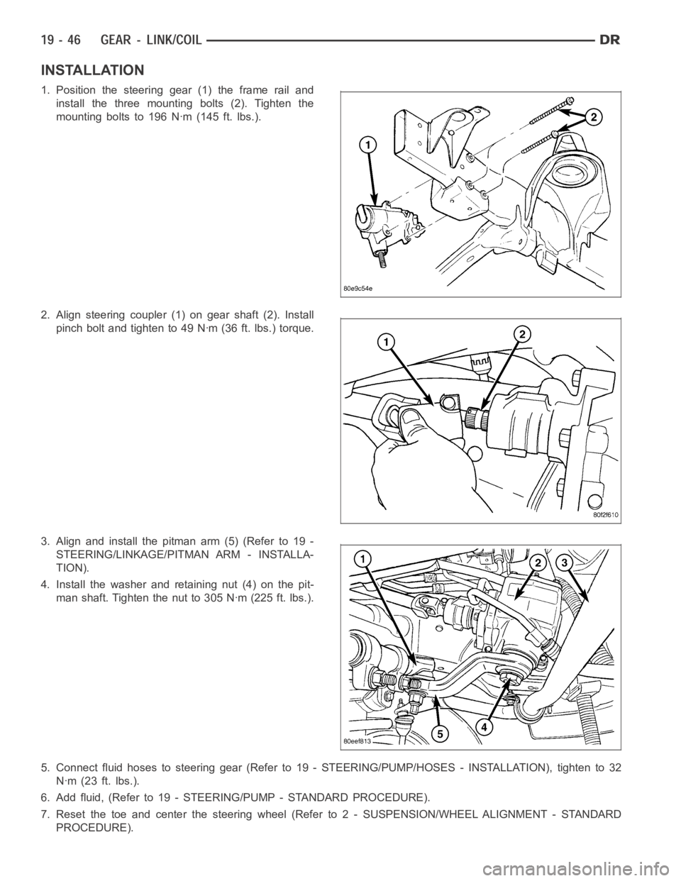
INSTALLATION
1. Position the steering gear (1) the frame rail and
install the three mounting bolts (2). Tighten the
mounting bolts to 196 Nꞏm (145 ft. lbs.).
2. Align steering coupler (1) on gear shaft (2). Install
pinch bolt and tighten to 49 Nꞏm (36 ft. lbs.) torque.
3. Align and install the pitman arm (5) (Refer to 19 -
STEERING/LINKAGE/PITMAN ARM - INSTALLA-
TION).
4. Install the washer and retaining nut (4) on the pit-
man shaft. Tighten the nut to 305 Nꞏm (225 ft. lbs.).
5. Connect fluid hoses to steering gear (Refer to 19 - STEERING/PUMP/HOSES- INSTALLATION), tighten to 32
Nꞏm (23 ft. lbs.).
6. Add fluid, (Refer to 19 - STEERING/PUMP - STANDARD PROCEDURE).
7. Reset the toe and center the steering wheel (Refer to 2 - SUSPENSION/WHEELALIGNMENT - STANDARD
PROCEDURE).
Page 3375 of 5267

DISASSEMBLY
1. Drain fluid from transmission.
2. Clean exterior of transmission with suitable solvent
or pressure washer.
3. Remove the torque converter from the transmis-
sion.
4. Remove the manual shift lever (1) from the
transmission.
5. Remove the input (3), output (1), and line pressure
sensors (2) from the transmission case.
6. Inspect the ends of the sensors for debris, which
may indicate the nature of the transmission failure.
7. Install Support Stand 8257 (1) onto the transmis-
sion case.
Page 3381 of 5267
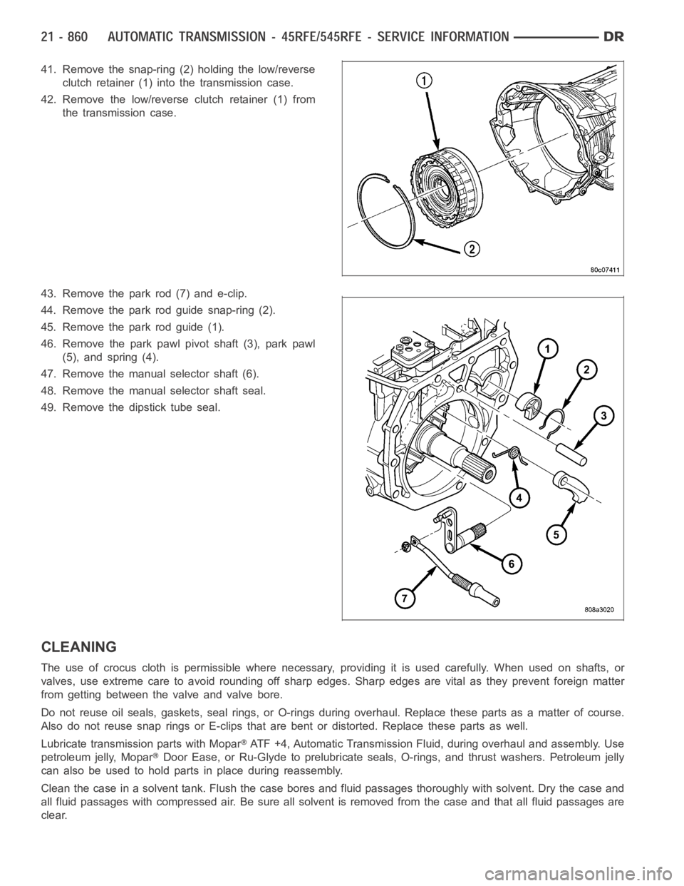
41. Remove the snap-ring (2) holding the low/reverse
clutch retainer (1) into the transmission case.
42. Remove the low/reverse clutch retainer (1) from
the transmission case.
43. Remove the park rod (7) and e-clip.
44. Remove the park rod guide snap-ring (2).
45. Remove the park rod guide (1).
46. Remove the park pawl pivot shaft (3), park pawl
(5), and spring (4).
47. Remove the manual selector shaft (6).
48. Remove the manual selector shaft seal.
49. Remove the dipstick tube seal.
CLEANING
The use of crocus cloth is permissible where necessary, providing it is usedcarefully.Whenusedonshafts,or
valves, use extreme care to avoid rounding off sharp edges. Sharp edges arevital as they prevent foreign matter
from getting between the valve and valve bore.
Do not reuse oil seals, gaskets, seal rings, or O-rings during overhaul. Replace these parts as a matter of course.
Also do not reuse snap rings or E-clips that are bent or distorted. Replace these parts as well.
Lubricate transmission parts with Mopar
ATF +4, Automatic Transmission Fluid, during overhaul and assembly. Use
petroleum jelly, Mopar
Door Ease, or Ru-Glyde to prelubricate seals, O-rings, and thrust washers. Petroleum jelly
canalsobeusedtoholdpartsinplaceduringreassembly.
Clean the case in a solvent tank. Flush the case bores and fluid passages thoroughly with solvent. Dry the case and
all fluid passages with compressed air. Be sure all solvent is removed fromthe case and that all fluid passages are
clear.
Page 3827 of 5267
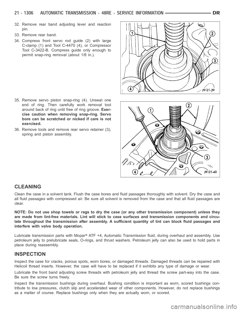
32. Remove rear band adjusting lever and reaction
pin.
33. Remove rear band.
34. Compress front servo rod guide (2) with large
C-clamp (1) and Tool C-4470 (4), or Compressor
Tool C-3422-B. Compress guide only enough to
permit snap-ring removal (about 1/8 in.).
35. Remove servo piston snap-ring (4). Unseat one
end of ring. Then carefully work removal tool
around back of ring until free of ring groove.Exer-
cise caution when removing snap-ring. Servo
bore can be scratched or nicked if care is not
exercised.
36. Remove tools and remove rear servo retainer (3),
spring and piston assembly.
CLEANING
Clean the case in a solvent tank. Flush the case bores and fluid passages thoroughly with solvent. Dry the case and
all fluid passages with compressed air. Be sure all solvent is removed fromthe case and that all fluid passages are
clear.
NOTE: Do not use shop towels or rags to dry the case (or any other transmission component) unless they
aremadefromlint-freematerials.Lintwillsticktocasesurfacesandtransmission components and circu-
late throughout the transmission after assembly. A sufficient quantity of lint can block fluid passages and
interfere with valve body operation.
Lubricate transmission parts with Mopar
ATF +4, Automatic Transmission fluid, during overhaul and assembly. Use
petroleum jelly to prelubricate seals, O-rings, and thrust washers. Petroleumjellycanalsobeusedtoholdpartsin
place during reassembly.
INSPECTION
Inspect the case for cracks, porous spots, worn bores, or damaged threads.Damaged threads can be repaired with
Helicoil thread inserts. However, the case will have to be replaced if it exhibits any type of damage or wear.
Lubricate the front band adjusting screw threads with petroleum jelly andthread the screw part-way into the case.
Be sure the screw turns freely.
Inspect the transmission bushings during overhaul. Bushing condition isimportant as worn, scored bushings con-
tribute to low pressures, clutch slipand accelerated wear of other components. However, do not replace bushings
as a matter of course. Replace bushings only when they are actually worn, orscored.
Page 3828 of 5267
The use of crocus cloth is permissible where necessary, providing it is usedcarefully.Whenusedonshafts,or
valves, use extreme care to avoid rounding off sharp edges. Sharp edges arevital as they prevent foreign matter
from getting between the valve and valve bore.
Do not reuse oil seals, gaskets, seal rings, or O-rings during overhaul. Replace these parts as a matter of course.
Also do not reuse snap rings or E-clips that are bent or distorted. Replace these parts as well.
ASSEMBLY
Do not allow dirt, grease, or foreign material to enter the case or transmission components during assembly. Keep
the transmission case and components clean. Also make sure the tools and workbench area used for reassembly
operations are equally clean.
Shop towels used for wiping off tools and your hands must be made fromlint freematerials. Lint will stick to trans-
mission parts and could interfere with valve operation or even restrict fluid passages.
Lubricate transmission clutch and gear components with Mopar
ATF +4 during reassembly. Soak clutch discs in
transmission fluid before installation.
Use petroleum jelly on piston seals and o-rings to ease installation. Petroleumjellycanalsobeusedtolubricate
and hold thrust washers and plates in position during assembly.
Do not use chassis grease, bearing grease, white grease, or similar lubricants on any part.These types of
lubricants can eventually block or restrict fluid passages and valve operation. Use petroleum jelly only.
Do not force parts into place. The transmission components and sub-assemblies are easily installed by hand when
properly aligned. If a part seems difficult to install, it is either misaligned or incorrectly assembled. Verify that thrust
washers, thrust plates and seal rings are correctly positioned.
The planetary geartrain, front/rear clutch assemblies and oil pump are all much easier to install when the transmis-
sion case is upright. Either tilt the case upward with wood blocks, or cut a hole in the bench large enough for the
intermediate shaft and rear support. Then lower the shaft and support intothe hole and support the rear of the case
directly on the bench.
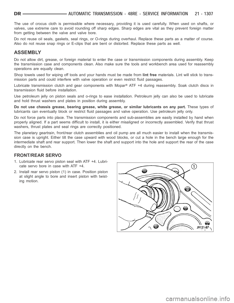
FRONT/REAR SERVO
1. Lubricate rear servo piston seal with ATF +4. Lubri-
cateservoboreincasewithATF+4.
2. Install rear servo piston (1) in case. Position piston
at slight angle to bore and insert piston with twist-
ing motion.