2006 DODGE RAM SRT-10 bolt pattern
[x] Cancel search: bolt patternPage 1553 of 5267
BLOCK-ENGINE
DESCRIPTION
The cylinder block is made of cast iron.The block is a closed deck design with the left bank forward. To provide
high rigidity and improved NVH an enhanced compacted graphite bedplate isbolted to the block. The block design
allows coolant flow between the cylinders bores, and an internal coolant bypass to a single poppet inlet thermostat
is included in the cast aluminum front cover.
STANDARD PROCEDURE - CYLINDER BORE HONING
Before honing, stuff plenty of clean shop towels under
the bores and over the crankshaft to keep abrasive
materials from entering the crankshaft area.
1. Used carefully, the Cylinder Bore Sizing Hone
C-823, equipped with 220 grit stones, is the best
tool for this job. In addition to deglazing, it will
reduce taper and out-of-round, as well as removing
light scuffing, scoring and scratches. Usually, a few
strokes will clean up a bore and maintain the
required limits.
CAUTION: DO NOT use rigid type hones to remove
cylinder wall glaze.
2. Deglazing of the cylinder walls may be done if the
cylinder bore is straight and round. Use a cylinder
surfacing hone, Honing Tool C-3501, equipped with
280 grit stones (C-3501-3810). about 20-60
strokes, depending on the bore condition, will be
sufficient to provide a satisfactory surface. Using
honing oil C-3501-3880, or a light honing oil, avail-
able from major oil distributors.
CAUTION: DO NOT use engine or transmission oil, mineral spirits, or kerosene.
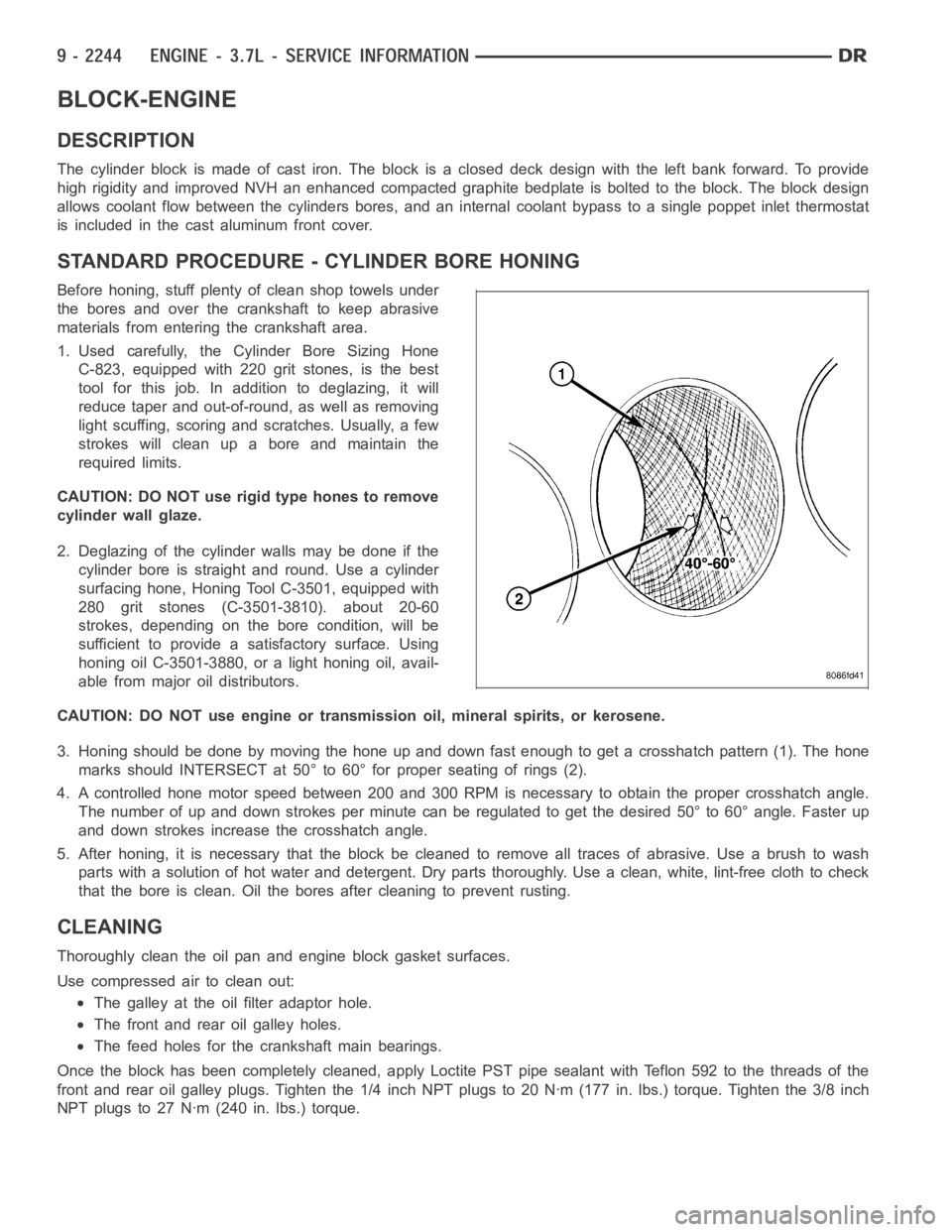
3. Honing should be done by moving the hone up and down fast enough to get a crosshatch pattern (1). The hone
marks should INTERSECT at 50° to 60° for proper seating of rings (2).
4. A controlled hone motor speed between 200 and 300 RPM is necessary to obtain the proper crosshatch angle.
The number of up and down strokes per minute can be regulated to get the desired 50° to 60° angle. Faster up
and down strokes increase the crosshatch angle.
5. After honing, it is necessary that the block be cleaned to remove all traces of abrasive. Use a brush to wash
parts with a solution of hot water and detergent. Dry parts thoroughly. Usea clean, white, lint-free cloth to check
that the bore is clean. Oil the bores after cleaning to prevent rusting.
CLEANING
Thoroughly clean the oil pan and engine block gasket surfaces.
Use compressed air to clean out:
The galley at the oil filter adaptor hole.
The front and rear oil galley holes.
The feed holes for the crankshaft main bearings.
Once the block has been completely cleaned, apply Loctite PST pipe sealantwith Teflon 592 to the threads of the
front and rear oil galley plugs. Tighten the 1/4 inch NPT plugs to 20 Nꞏm (177in. lbs.) torque. Tighten the 3/8 inch
NPT plugs to 27 Nꞏm (240 in. lbs.) torque.
Page 1688 of 5267
ENGINE BLOCK
DESCRIPTION
The cylinder block is made of cast iron.The block is a closed deck design with the left bank forward. To provide
high rigidity and improved NVH an enhanced compacted graphite bedplate isbolted to the block. The block design
allows coolant flow between the cylinders bores, and an internal coolant bypass to a single poppet inlet thermostat
is included in the cast aluminum front cover.
STANDARD PROCEDURE - CYLINDER BORE HONING
Before honing, stuff plenty of clean shop towels under
the bores and over the crankshaft to keep abrasive
materials from entering the crankshaft area.
1. Used carefully, the Cylinder Bore Sizing Hone
C-823, equipped with 220 grit stones, is the best
tool for this job. In addition to deglazing, it will
reduce taper and out-of-round, as well as removing
light scuffing, scoring and scratches. Usually, a few
strokes will clean up a bore and maintain the
required limits.
CAUTION: DO NOT use rigid type hones to remove
cylinder wall glaze.
2. Deglazing of the cylinder walls may be done if the
cylinder bore is straight and round. Use a cylinder
surfacing hone, Honing Tool C-3501, equipped with
280 grit stones (C-3501-3810). about 20-60
strokes, depending on the bore condition, will be
sufficient to provide a satisfactory surface. Using
honing oil C-3501-3880, or a light honing oil, avail-
able from major oil distributors.
CAUTION: DO NOT use engine or transmission oil, mineral spirits, or kerosene.
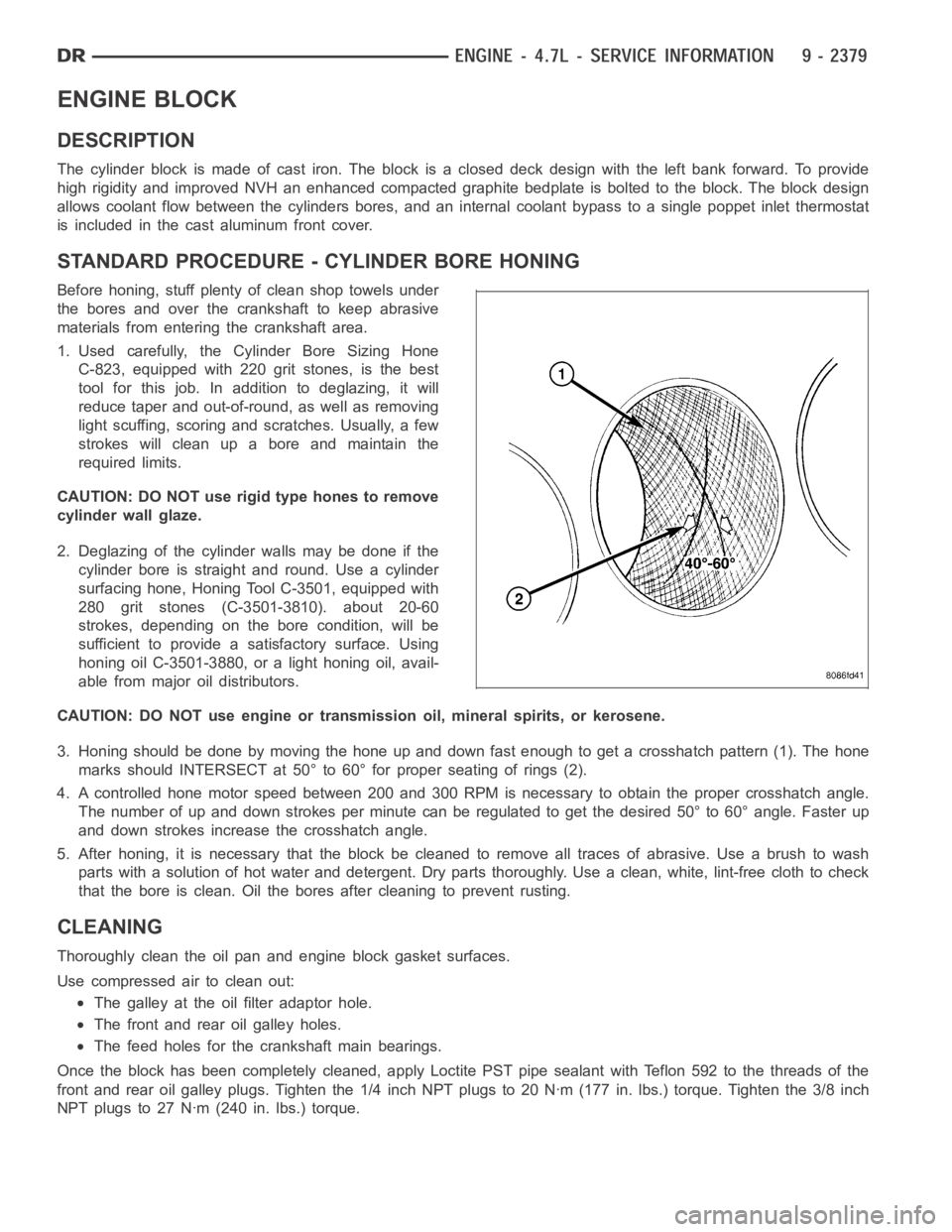
3. Honing should be done by moving the hone up and down fast enough to get a crosshatch pattern (1). The hone
marks should INTERSECT at 50° to 60° for proper seating of rings (2).
4. A controlled hone motor speed between 200 and 300 RPM is necessary to obtain the proper crosshatch angle.
The number of up and down strokes per minute can be regulated to get the desired 50° to 60° angle. Faster up
and down strokes increase the crosshatch angle.
5. After honing, it is necessary that the block be cleaned to remove all traces of abrasive. Use a brush to wash
parts with a solution of hot water and detergent. Dry parts thoroughly. Usea clean, white, lint-free cloth to check
that the bore is clean. Oil the bores after cleaning to prevent rusting.
CLEANING
Thoroughly clean the oil pan and engine block gasket surfaces.
Use compressed air to clean out:
The galley at the oil filter adaptor hole.
The front and rear oil galley holes.
The feed holes for the crankshaft main bearings.
Once the block has been completely cleaned, apply Loctite PST pipe sealantwith Teflon 592 to the threads of the
front and rear oil galley plugs. Tighten the 1/4 inch NPT plugs to 20 Nꞏm (177in. lbs.) torque. Tighten the 3/8 inch
NPT plugs to 27 Nꞏm (240 in. lbs.) torque.
Page 1803 of 5267
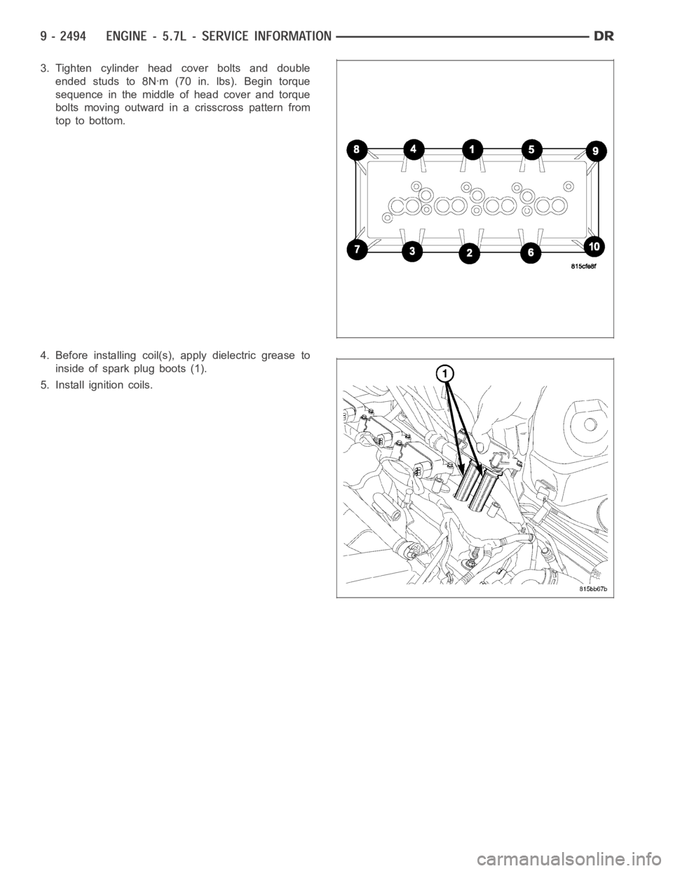
3. Tighten cylinder head cover bolts and double
ended studs to 8Nꞏm (70 in. lbs). Begin torque
sequence in the middle of head cover and torque
bolts moving outward in a crisscross pattern from
top to bottom.
4. Before installing coil(s), apply dielectric grease to
inside of spark plug boots (1).
5. Install ignition coils.
Page 1867 of 5267
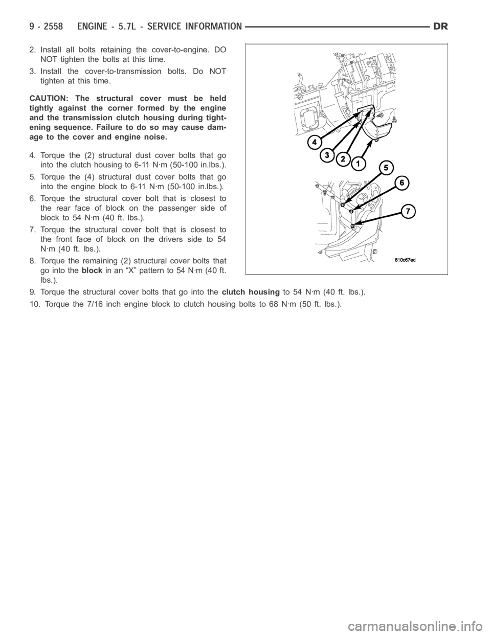
2. Install all bolts retaining the cover-to-engine. DO
NOT tighten the bolts at this time.
3. Install the cover-to-transmission bolts. Do NOT
tighten at this time.
CAUTION: The structural cover must be held
tightly against the corner formed by the engine
and the transmission clutch housing during tight-
ening sequence. Failure to do so may cause dam-
age to the cover and engine noise.
4. Torque the (2) structural dust cover bolts that go
into the clutch housing to 6-11 Nꞏm (50-100 in.lbs.).
5. Torque the (4) structural dust cover bolts that go
into the engine block to 6-11 Nꞏm (50-100 in.lbs.).
6. Torque the structural cover bolt that is closest to
the rear face of block on the passenger side of
blockto54Nꞏm(40ft.lbs.).
7. Torque the structural cover bolt that is closest to
the front face of block on the drivers side to 54
Nꞏm (40 ft. lbs.).
8. Torque the remaining (2) structural cover bolts that
go into theblockin an “X” pattern to 54 Nꞏm (40 ft.
lbs.).
9. Torque the structural cover bolts that go into theclutch housingto 54 Nꞏm (40 ft. lbs.).
10. Torque the 7/16 inch engine block to clutch housing bolts to 68 Nꞏm (50 ft.lbs.).
Page 1887 of 5267
MANIFOLD - INTAKE
DESCRIPTION
The intake manifold is made of a composite material and features long runners which maximizes low end torque.
The intake manifold uses single plane sealing which consist of eight individual press in place port gaskets to prevent
leaks.
DIAGNOSIS AND TESTING - INTAKE MANIFOLD LEAKAGE
An intake manifold air leak is characterized by lower than normal manifoldvacuum. Also, one or more cylinders may
not be functioning.
WARNING: USE EXTREME CAUTION WHEN THE ENGINE IS OPERATING. DO NOT STAND IN ADIRECT LINE
WITH THE FAN. DO NOT PUT YOUR HANDS NEAR THE PULLEYS, BELTS OR THE FAN. DO NOT WEAR
LOOSE CLOTHING.
1. Start the engine.
2. Spray a small stream of water at the suspected leak area.
3. If a change in RPM is observed the area of the suspected leak has been found.
4. Repair as required.
REMOVAL
1. Disconnect negative cable from battery.
2. Remove resonator assembly and air inlet hose.
3. Disconnect electrical connectors for the following components:
Manifold Absolute Pressure (MAP) Sensor
Intake Air Temperature (IAT) Sensor
Throttle Position (TPS) Sensor
Coolant Temperature (CTS) Sensor
4. Disconnect brake booster hose and positive crankcase ventilation (PCV)hose.
5. Remove generator and set aside.
NOTE: It is not necessary to remove lines or remove freon from A/C compressor.
6. Remove air conditioning compressor and set aside..
7. Bleed fuel system (Refer to 14 - FUEL SYSTEM/FUEL DELIVERY - STANDARD PROCEDURE).
8. Remove intake manifold retaining fasteners in a crisscross pattern starting from the outside bolts and ending at
themiddlebolts.
9. Remove intake manifold and IAFM as an assembly.
CLEANING
NOTE: There is NO approved repair procedure for the intake manifold. If severe damage is found during
inspection, the intake manifold must be replaced.
Before installing the intake manifoldthoroughly clean the mating surfaces. Use a suitable cleaning solvent, then air
dry.
Page 1888 of 5267
INSPECTION
1. Inspect the intake sealing surface for cracks, nicks and distortion.
2. Inspect the intake manifold vacuum hose fittings for looseness or blockage.
3. Inspect the manifold to throttlebody mating surface for cracks, nicks and distortion.
INSTALLATION
1. Install intake manifold seals.
2. Position intake manifold and IAFM.
3. Install intake manifold retaining bolts, and tighten in sequence from the middle bolts towards the outside in a
crisscross pattern. Torque fasteners to 12 Nꞏm (105 in. lbs.).
4. Connect electrical connectors for the following components:
Manifold Absolute Pressure (MAP) Sensor
Intake Air Temperature (IAT) Sensor
Throttle Position (TPS) Sensor
Coolant Temperature (CTS) Sensor
Idle Air Control (IAC) Motor
5. Install generator.
6. Install A/C compressor.
7. Connect Brake booster hose and Positive crankcase ventilation (PCV) hose.
8. Install resonator assembly and air inlet hose.
9. Connect negative cable to battery.
Page 1980 of 5267
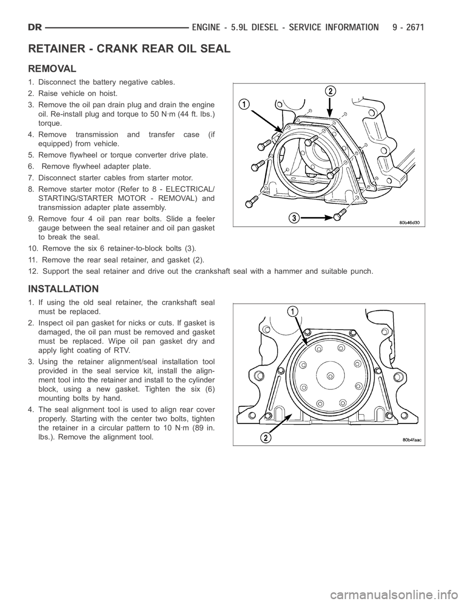
RETAINER - CRANK REAR OIL SEAL
REMOVAL
1. Disconnect the battery negative cables.
2. Raise vehicle on hoist.
3. Remove the oil pan drain plug and drain the engine
oil. Re-install plug and torque to 50 Nꞏm (44 ft. lbs.)
torque.
4. Remove transmission and transfer case (if
equipped) from vehicle.
5. Remove flywheel or torque converter drive plate.
6. Remove flywheel adapter plate.
7. Disconnect starter cables from starter motor.
8. Remove starter motor (Refer to 8 - ELECTRICAL/
STARTING/STARTER MOTOR - REMOVAL) and
transmission adapter plate assembly.
9. Remove four 4 oil pan rear bolts. Slide a feeler
gauge between the seal retainer and oil pan gasket
to break the seal.
10. Remove the six 6 retainer-to-block bolts (3).
11. Remove the rear seal retainer, and gasket (2).
12. Support the seal retainer and drive out the crankshaft seal with a hammer and suitable punch.
INSTALLATION
1. If using the old seal retainer, the crankshaft seal
must be replaced.
2. Inspect oil pan gasket for nicks or cuts. If gasket is
damaged, the oil pan must be removed and gasket
must be replaced. Wipe oil pan gasket dry and
apply light coating of RTV.
3. Using the retainer alignment/seal installation tool
provided in the seal service kit, install the align-
ment tool into the retainer and install to the cylinder
block, using a new gasket. Tighten the six (6)
mounting bolts by hand.
4. The seal alignment tool is used to align rear cover
properly. Starting with the center two bolts, tighten
the retainer in a circular pattern to 10 Nꞏm (89 in.
lbs.). Remove the alignment tool.
Page 2104 of 5267
BLOCK-ENGINE
DESCRIPTION
The cylinder block is made of a sand-cast aluminum alloy. The cylinder block has interference-fit cast iron cylinder
liners. The cylinder liners are thermally installed during block manufacturing; they are not serviceable items.
Six iron main bearing caps use four bolts per cap; two vertical and two horizontal. A crankshaft oil scraper is
attached to the main bearing caps via extended main bearing cap bolts and nuts.
STANDARD PROCEDURE - CYLINDER BORE HONING
Before honing, stuff plenty of clean shop towels under
the bores and over the crankshaft to keep abrasive
materials from entering the crankshaft area.
1. Used carefully, the Cylinder Bore Sizing Hone
C-823, equipped with 220 grit stones, is the best
tool for this job. In addition to deglazing, it will
reduce taper and out-of-round, as well as removing
light scuffing, scoring and scratches. Usually, a few
strokes will clean up a bore and maintain the
required limits.
CAUTION: DO NOT use rigid type hones to remove
cylinder wall glaze.
2. Deglazing of the cylinder walls may be done if the
cylinder bore is straight and round. Use a cylinder
surfacing hone, Honing Tool C-3501, equipped with
280 grit stones (C-3501-3810). about 20-60
strokes, depending on the bore condition, will be
sufficient to provide a satisfactory surface. Using
honing oil C-3501-3880, or a light honing oil, avail-
able from major oil distributors.
CAUTION: DO NOT use engine or transmission oil, mineral spirits, or kerosene.
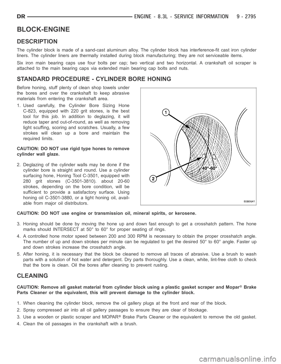
3. Honing should be done by moving the hone up and down fast enough to get a crosshatch pattern. The hone
marks should INTERSECT at 50° to 60° for proper seating of rings.
4. A controlled hone motor speed between 200 and 300 RPM is necessary to obtain the proper crosshatch angle.
The number of up and down strokes per minute can be regulated to get the desired 50° to 60° angle. Faster up
and down strokes increase the crosshatch angle.
5. After honing, it is necessary that the block be cleaned to remove all traces of abrasive. Use a brush to wash
parts with a solution of hot water and detergent. Dry parts thoroughly. Usea clean, white, lint-free cloth to check
that the bore is clean. Oil the bores after cleaning to prevent rusting.
CLEANING
CAUTION: Remove all gasket material from cylinder block using a plastic gasket scraper and MoparBrake
Parts Cleaner or the equivalent, this will prevent damage to the cylinder block.
1. When cleaning the cylinder block, remove the oil gallery plugs at the front and rear of the block.
2. Spray compressed air into all oil gallery passages to ensure they are clear of blockage.
3. Use a wooden or plastic scraper and MOPAR
Brake Parts Cleaner or the equivalent to remove the old gasket.
4. Clean the oil passages in the crankshaft with a brush.