2006 DODGE RAM SRT-10 gas type
[x] Cancel search: gas typePage 1495 of 5267
Refer to CYLINDER COMBUSTION PRESSURE LEAKAGE DIAGNOSIS CHART .
CYLINDER COMBUSTION PRESSURE LEAKAGE DIAGNOSIS CHART
CONDITION POSSIBLE CAUSE CORRECTION
AIR ESCAPES THROUGH
THROTTLE BODYIntake valve bent, burnt, or not
seated properlyInspect valve and valve seat.
Reface or replace, as necessary.
Inspect valve springs. Replace as
necessary.
AIR ESCAPES THROUGH
TAILPIPEExhaust valve bent, burnt, or not
seated properlyInspect valve and valve seat.
Reface or replace, as necessary.
Inspect valve springs. Replace as
necessary.
AIR ESCAPES THROUGH
RADIATORHead gasket leaking or cracked
cylinder head or blockRemove cylinder head and inspect.
Replace defective part
MORE THAN 50% LEAKAGE
FROM ADJACENT CYLINDERSHead gasket leaking or crack in
cylinder head or block between
adjacent cylindersRemove cylinder head and inspect.
Replace gasket, head, or block as
necessary
MORE THAN 25% LEAKAGE AND
AIR ESCAPES THROUGH OIL
FILLER CAP OPENING ONLYStuckorbrokenpistonrings;
cracked piston; worn rings and/or
cylinder wallInspect for broken rings or piston.
Measure ring gap and cylinder
diameter, taper and out-of-round.
Replace defective part as necessary
STANDARD PROCEDURE
STANDARD PROCEDURE - REPAIR DAMAGED OR WORN THREADS
CAUTION: Be sure that the tapped holes maintain the original center line.
Damaged or worn threads can be repaired. Essentially, this repair consistsof:
Drilling out worn or damaged threads.
Tapping the hole with a special Heli-Coil Tap, or equivalent.
Installing an insert into the tapped hole to bring the hole back to its original thread size.
STANDARD PROCEDURE - FORM-IN-PLACE GASKETS AND SEALERS
There are numerous places where form-in-place gaskets are used on the engine. Care must be taken when apply-
ing form-in-place gaskets to assure obtaining the desired results.Do not use form-in-place gasket material
unless specified.Bead size, continuity, and location are of great importance. Too thin a bead can result in leakage
while too much can result in spill-overwhich can break off and obstruct fluid feed lines. A continuous bead of the
proper width is essential to obtain a leak-free gasket.
There are numerous types of form-in-place gasket materials that are used in the engine area. Mopar
Engine RTV
GEN II, Mopar
ATF-RTV, and MoparGasket Maker gasket materials, each have different properties and can not
be used in place of the other.
MOPAR
ENGINE RTV GEN II
Mopar
Engine RTV GEN II is used to seal components exposed to engine oil. This material is a specially designed
black silicone rubber RTV that retains adhesion and sealing properties when exposed to engine oil. Moisture in the
air causes the material to cure. This material is available in three ounce tubes and has a shelf life of one year. After
one year this material will not properly cure. Always inspect the package for the expiration date before use.
MOPAR
AT F R T V
Mopar
ATF RTV is a specifically designed black silicone rubber RTV that retains adhesion and sealing properties
to seal components exposed to automatic transmission fluid, engine coolants, and moisture. This material is avail-
able in three ounce tubes and has a shelf life of one year. After one year thismaterial will not properly cure. Always
inspect the package for the expiration date before use.
MOPAR
GASKET MAKER
Page 1496 of 5267
MoparGasket Maker is an anaerobic type gasket material. The material cures in the absence of air when
squeezed between two metallic surfaces. It will not cure if left in the uncovered tube. The anaerobic material is for
use between two machined surfaces. Do not use on flexible metal flanges.
MOPAR
GASKET SEALANT
Mopar
Gasket Sealant is a slow drying, permanently soft sealer. This material isrecommended for sealing
threaded fittings and gaskets against leakage of oil and coolant. Can be used on threaded and machined parts
under all temperatures. This material is used on engines with multi-layersteel (MLS) cylinder head gaskets. This
material also will prevent corrosion. Mopar
Gasket Sealant is available in a 13 oz. aerosol can or 4oz./16 oz. can
w/applicator.
FORM-IN-PLACE GASKET AND SEALER APPLICATION
Assembling parts using a form-in-place gasket requires care but it’s easier than using precut gaskets.
Mopar
Gasket Maker material should be applied sparingly 1 mm (0.040 in.) diameter or less of sealant to one
gasket surface. Be certain the material surrounds each mounting hole. Excess material can easily be wiped off.
Components should be torqued in place within 15 minutes. The use of a locating dowel is recommended during
assembly to prevent smearing material off the location.
Mopar
Engine RTV GEN II or ATF RTV gasket material should be applied in a continuous bead approximately 3
mm (0.120 in.) in diameter. All mounting holes must be circled. For corner sealing, a 3.17 or 6.35 mm (1/8 or 1/4 in.)
drop is placed in the center of the gasket contact area. Uncured sealant maybe removed with a shop towel. Com-
ponents should be torqued in place while the sealant is still wet to the touch (within 10 minutes). The usage of a
locating dowel is recommended during assembly to prevent smearing material off the location.
Mopar
Gasket Sealant in an aerosol can should be applied using a thin, even coat sprayed completely over both
surfaces to be joined, and both sides of a gasket. Then proceed with assembly. Material in a can w/applicator can
be brushed on evenly over the sealing surfaces. Material in an aerosol can shouldbeusedonengineswithmulti-
layer steel gaskets.
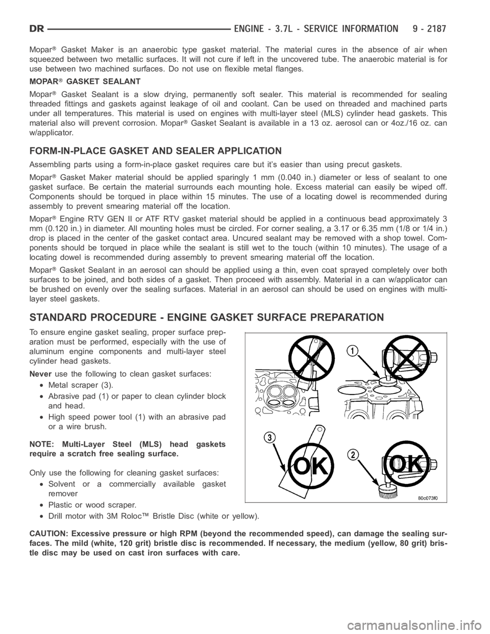
STANDARD PROCEDURE - ENGINE GASKET SURFACE PREPARATION
To ensure engine gasket sealing, proper surface prep-
aration must be performed, especially with the use of
aluminum engine components and multi-layer steel
cylinder head gaskets.
Neveruse the following to clean gasket surfaces:
Metal scraper (3).
Abrasive pad (1) or paper to clean cylinder block
and head.
High speed power tool (1) with an abrasive pad
orawirebrush.
NOTE: Multi-Layer Steel (MLS) head gaskets
require a scratch free sealing surface.
Only use the following for cleaning gasket surfaces:
Solvent or a commercially available gasket
remover
Plastic or wood scraper.
Drill motor with 3M Roloc™ Bristle Disc (white or yellow).
CAUTION: Excessive pressure or high RPM (beyond the recommended speed), can damage the sealing sur-
faces. The mild (white, 120 grit) bristle disc is recommended. If necessary, the medium (yellow, 80 grit) bris-
tle disc may be used on cast iron surfaces with care.
Page 1553 of 5267
BLOCK-ENGINE
DESCRIPTION
The cylinder block is made of cast iron.The block is a closed deck design with the left bank forward. To provide
high rigidity and improved NVH an enhanced compacted graphite bedplate isbolted to the block. The block design
allows coolant flow between the cylinders bores, and an internal coolant bypass to a single poppet inlet thermostat
is included in the cast aluminum front cover.
STANDARD PROCEDURE - CYLINDER BORE HONING
Before honing, stuff plenty of clean shop towels under
the bores and over the crankshaft to keep abrasive
materials from entering the crankshaft area.
1. Used carefully, the Cylinder Bore Sizing Hone
C-823, equipped with 220 grit stones, is the best
tool for this job. In addition to deglazing, it will
reduce taper and out-of-round, as well as removing
light scuffing, scoring and scratches. Usually, a few
strokes will clean up a bore and maintain the
required limits.
CAUTION: DO NOT use rigid type hones to remove
cylinder wall glaze.
2. Deglazing of the cylinder walls may be done if the
cylinder bore is straight and round. Use a cylinder
surfacing hone, Honing Tool C-3501, equipped with
280 grit stones (C-3501-3810). about 20-60
strokes, depending on the bore condition, will be
sufficient to provide a satisfactory surface. Using
honing oil C-3501-3880, or a light honing oil, avail-
able from major oil distributors.
CAUTION: DO NOT use engine or transmission oil, mineral spirits, or kerosene.
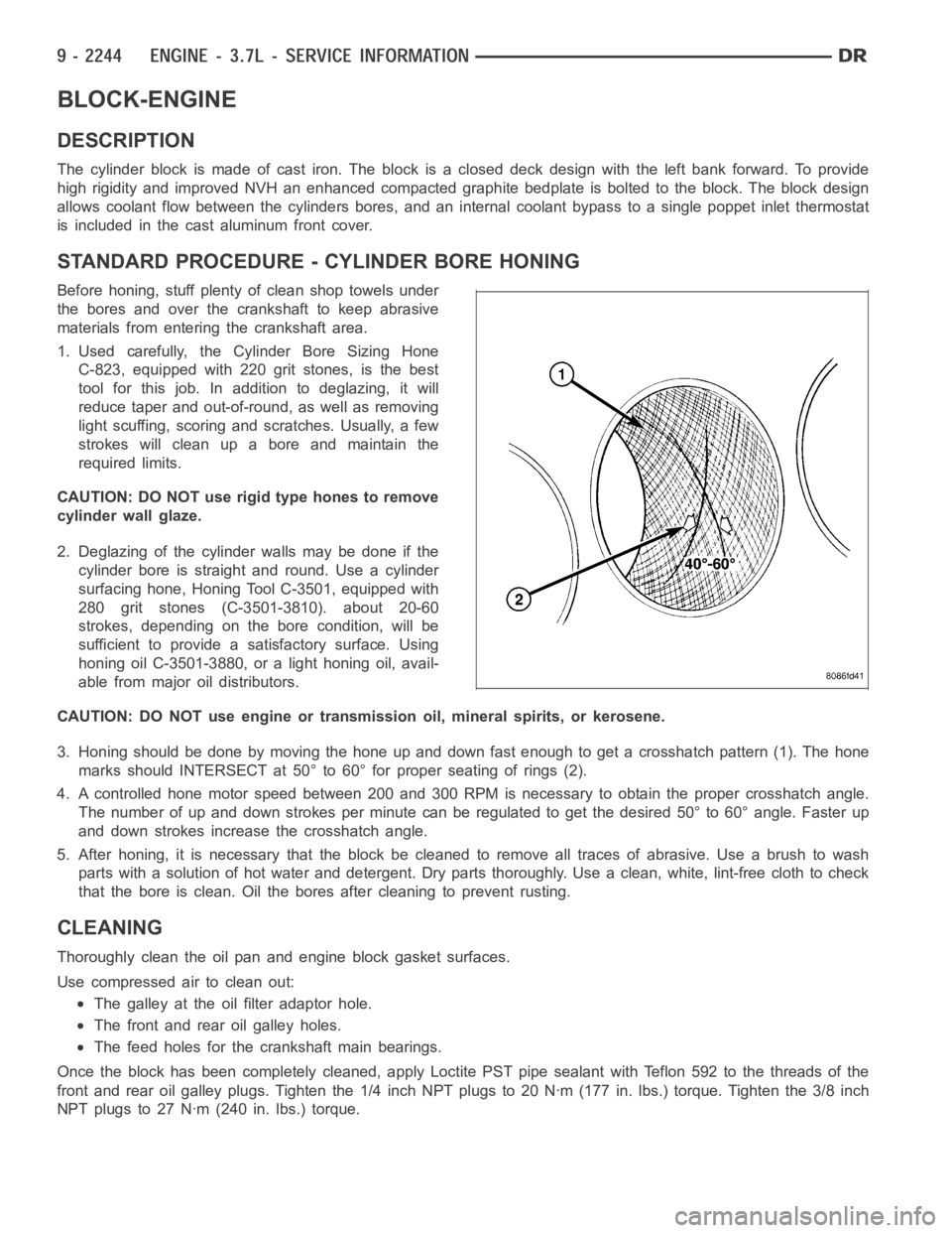
3. Honing should be done by moving the hone up and down fast enough to get a crosshatch pattern (1). The hone
marks should INTERSECT at 50° to 60° for proper seating of rings (2).
4. A controlled hone motor speed between 200 and 300 RPM is necessary to obtain the proper crosshatch angle.
The number of up and down strokes per minute can be regulated to get the desired 50° to 60° angle. Faster up
and down strokes increase the crosshatch angle.
5. After honing, it is necessary that the block be cleaned to remove all traces of abrasive. Use a brush to wash
parts with a solution of hot water and detergent. Dry parts thoroughly. Usea clean, white, lint-free cloth to check
that the bore is clean. Oil the bores after cleaning to prevent rusting.
CLEANING
Thoroughly clean the oil pan and engine block gasket surfaces.
Use compressed air to clean out:
The galley at the oil filter adaptor hole.
The front and rear oil galley holes.
The feed holes for the crankshaft main bearings.
Once the block has been completely cleaned, apply Loctite PST pipe sealantwith Teflon 592 to the threads of the
front and rear oil galley plugs. Tighten the 1/4 inch NPT plugs to 20 Nꞏm (177in. lbs.) torque. Tighten the 3/8 inch
NPT plugs to 27 Nꞏm (240 in. lbs.) torque.
Page 1585 of 5267
LUBRICATION
DESCRIPTION
The lubrication system is a full flow filtration pressure feed type.
OPERATION
Engine Lubrication Flow Chart - Block: Table 1
FROM TO
Oil Pickup Tube Oil Pump
Oil Pump Oil Filter
Oil Filter Block Main Oil Gallery
Block Main Oil Gallery 1. Crankshaft Main Journal
2. Left Cylinder Head*
3. Right Cylinder Head*
4. Counterbalance Shaft Rear Journal
Crankshaft Main Journals Crankshaft Rod Journals
Crankshaft Number One Main Journal 1. Front Timing Chain Idler Shaft
2. Counterbalance Shaft - Front Journal
3. Both Secondary Chain Tensioners
Left Cylinder Head Refer to Engine Lubrication Flow Chart - Cylinder
Heads: Table 2
Right Cylinder Head Refer to Engine Lubrication Flow Chart - Cylinder
Heads: Table 2
* The cylinder head gaskets have an oil restricter to control oil flow to thecylinder heads
Engine Lubrication Flow Chart - Cylinder Heads: Table 2
FROM TO
Cylinder Head Oil Port (in bolt hole) Diagonal Cross Drilling to Main Oil Gallery
Main Oil Gallery (drilled through head from rear to front) 1. Base of Camshaft Towers
2. Lash Adjuster Towers
Base of Camshaft Towers Vertical Drilling Through Tower to Camshaft Bearings**
Lash Adjuster Towers Diagonal Drillings to Hydraulic Lash Adjuster Pockets
** The number three camshaft bearing journal feeds oil into the hollow camshaft tubes. Oil is routed to the intake
lobes, which have oil passages drilled into them to lubricate the rocker arms.
Page 1597 of 5267
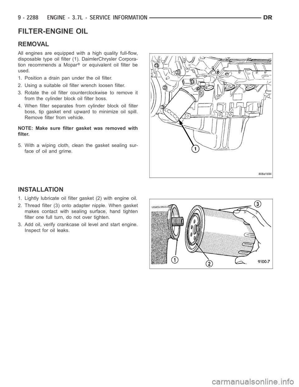
FILTER-ENGINE OIL
REMOVAL
All engines are equipped with a high quality full-flow,
disposable type oil filter (1). DaimlerChrysler Corpora-
tion recommends a Mopar
or equivalent oil filter be
used.
1. Position a drain pan under the oil filter.
2. Using a suitable oil filter wrench loosen filter.
3. Rotate the oil filter counterclockwise to remove it
from the cylinder block oil filter boss.
4. When filter separates from cylinder block oil filter
boss, tip gasket end upward to minimize oil spill.
Remove filter from vehicle.
NOTE: Make sure filter gasket was removed with
filter.
5. With a wiping cloth, clean the gasket sealing sur-
face of oil and grime.
INSTALLATION
1. Lightly lubricate oil filter gasket (2) with engine oil.
2. Thread filter (3) onto adapter nipple. When gasket
makes contact with sealing surface, hand tighten
filter one full turn, do not over tighten.
3. Add oil, verify crankcase oil level and start engine.
Inspect for oil leaks.
Page 1629 of 5267
CONDITION POSSIBLE CAUSE CORRECTION
MORE THAN 25% LEAKAGE AND
AIR ESCAPES THROUGH OIL
FILLER CAP OPENING ONLYStuckorbrokenpistonrings;
cracked piston; worn rings and/or
cylinder wallInspect for broken rings or piston.
Measure ring gap and cylinder
diameter, taper and out-of-round.
Replace defective part as necessary
DIAGNOSIS AND TESTING - ENGINE DIAGNOSIS - INTRODUCTION
Engine diagnosis is helpful in determining the causes of malfunctions notdetected and remedied by routine main-
tenance.
These malfunctions may be classified as either performance (e.g., engineidles rough and stalls) or mechanical
(e.g., a strange noise).
(Refer to 9 - ENGINE - DIAGNOSIS AND TESTING) - PERFORMANCE and (Refer to 9 - ENGINE - DIAGNOSIS
AND TESTING)—MECHANICAL for possible causes and corrections of malfunctions. (Refer to 14 - FUEL SYSTEM/
FUEL DELIVERY - DIAGNOSIS AND TESTING) and (Refer to 14 - FUEL SYSTEM/FUEL INJECTION - DIAGNO-
SIS AND TESTING) for the fuel system diagnosis.
Additional tests and diagnostic procedures may be necessary for specificengine malfunctions that can not be iso-
lated with the Service Diagnosis charts. Information concerning additional tests and diagnosis is provided within the
following diagnosis:
Cylinder Compression Pressure Test (Refer to 9 - ENGINE - DIAGNOSIS AND TESTING).
Cylinder Combustion Pressure LeakageTest (Refer to 9 - ENGINE - DIAGNOSISAND TESTING).
Engine Cylinder Head Gasket Failure Diagnosis (Refer to 9 - ENGINE/CYLINDER HEAD - DIAGNOSIS AND
TESTING).
Intake Manifold Leakage Diagnosis (Refer to 9 - ENGINE/MANIFOLDS/INTAKEMANIFOLD - DIAGNOSIS
AND TESTING).
STANDARD PROCEDURE
STANDARD PROCEDURE - REPAIR DAMAGED OR WORN THREADS
CAUTION: Be sure that the tapped holes maintain the original center line.
Damaged or worn threads can be repaired. Essentially, this repair consistsof:
Drilling out worn or damaged threads.
Tapping the hole with a special Heli-Coil Tap, or equivalent.
Installing an insert into the tapped hole to bring the hole back to its original thread size.
STANDARD PROCEDURE - FORM-IN-PLACE GASKETS AND SEALERS
There are numerous places where form-in-place gaskets are used on the engine. Care must be taken when apply-
ing form-in-place gaskets to assure obtaining the desired results.Do not use form-in-place gasket material
unless specified.Bead size, continuity, and location are of great importance. Too thin a bead can result in leakage
while too much can result in spill-overwhich can break off and obstruct fluid feed lines. A continuous bead of the
proper width is essential to obtain a leak-free gasket.
There are numerous types of form-in-place gasket materials that are used in the engine area. Mopar
Engine RTV
GEN II, Mopar
ATF-RTV, and MoparGasket Maker gasket materials, each have different properties and can not
be used in place of the other.
MOPAR
ENGINE RTV GEN II
Mopar
Engine RTV GEN II is used to seal components exposed to engine oil. This material is a specially designed
black silicone rubber RTV that retains adhesion and sealing properties when exposed to engine oil. Moisture in the
air causes the material to cure. This material is available in three ounce tubes and has a shelf life of one year. After
one year this material will not properly cure. Always inspect the package for the expiration date before use.
MOPAR
AT F R T V
Mopar
ATF RTV is a specifically designed black silicone rubber RTV that retains adhesion and sealing properties
to seal components exposed to automatic transmission fluid, engine coolants, and moisture. This material is avail-
Page 1630 of 5267
able in three ounce tubes and has a shelf life of one year. After one year thismaterial will not properly cure. Always
inspect the package for the expiration date before use.
MOPAR
GASKET MAKER
Mopar
Gasket Maker is an anaerobic type gasket material. The material cures in the absence of air when
squeezed between two metallic surfaces. It will not cure if left in the uncovered tube. The anaerobic material is for
use between two machined surfaces. Do not use on flexible metal flanges.
MOPAR
GASKET SEALANT
Mopar
Gasket Sealant is a slow drying, permanently soft sealer. This material isrecommended for sealing
threaded fittings and gaskets against leakage of oil and coolant. Can be used on threaded and machined parts
under all temperatures. This material is used on engines with multi-layersteel (MLS) cylinder head gaskets. This
material also will prevent corrosion. Mopar
Gasket Sealant is available in a 13 oz. aerosol can or 4oz./16 oz. can
w/applicator.
FORM-IN-PLACE GASKET AND SEALER APPLICATION
Assembling parts using a form-in-place gasket requires care but it’s easier than using precut gaskets.
Mopar
Gasket Maker material should be applied sparingly 1 mm (0.040 in.) diameter or less of sealant to one
gasket surface. Be certain the material surrounds each mounting hole. Excess material can easily be wiped off.
Components should be torqued in place within 15 minutes. The use of a locating dowel is recommended during
assembly to prevent smearing material off the location.
Mopar
Engine RTV GEN II or ATF RTV gasket material should be applied in a continuous bead approximately 3
mm (0.120 in.) in diameter. All mounting holes must be circled. For corner sealing, a 3.17 or 6.35 mm (1/8 or 1/4 in.)
drop is placed in the center of the gasket contact area. Uncured sealant maybe removed with a shop towel. Com-
ponents should be torqued in place while the sealant is still wet to the touch (within 10 minutes). The usage of a
locating dowel is recommended during assembly to prevent smearing material off the location.
Mopar
Gasket Sealant in an aerosol can should be applied using a thin, even coat sprayed completely over both
surfaces to be joined, and both sides of a gasket. Then proceed with assembly. Material in a can w/applicator can
be brushed on evenly over the sealing surfaces. Material in an aerosol can shouldbeusedonengineswithmulti-
layer steel gaskets.
REMOVAL
NOTE:Thisprocedureappliestoboththe4X2and4X4vehicles,stepsthatapply to the 4X4 vehicle only,
are identified.
1. Release fuel rail pressure (Refer to 14 - FUEL SYSTEM/FUEL DELIVERY - STANDARD PROCEDURE) then
disconnect the fuel supply quick connect fitting at the fuel rail (Refer to14 - FUEL SYSTEM/FUEL DELIVERY/
QUICK CONNECT FITTING - STANDARD PROCEDURE).
2. Disconnect the battery negative and positive cables.
3. Raise vehicle on hoist.
4. Remove exhaust crossover pipe from exhaust manifolds.
5.4X4 vehiclesDisconnect axle vent tube from left side engine mount.
6. Remove the through bolt retaining nut and bolt from both the left and right side engine mounts.
7.4X4 vehiclesRemove locknut from left and right side engine mount brackets.
8. Disconnect two ground straps from the lower left hand side and one groundstrap from the lower right hand side
of the engine.
Page 1688 of 5267
ENGINE BLOCK
DESCRIPTION
The cylinder block is made of cast iron.The block is a closed deck design with the left bank forward. To provide
high rigidity and improved NVH an enhanced compacted graphite bedplate isbolted to the block. The block design
allows coolant flow between the cylinders bores, and an internal coolant bypass to a single poppet inlet thermostat
is included in the cast aluminum front cover.
STANDARD PROCEDURE - CYLINDER BORE HONING
Before honing, stuff plenty of clean shop towels under
the bores and over the crankshaft to keep abrasive
materials from entering the crankshaft area.
1. Used carefully, the Cylinder Bore Sizing Hone
C-823, equipped with 220 grit stones, is the best
tool for this job. In addition to deglazing, it will
reduce taper and out-of-round, as well as removing
light scuffing, scoring and scratches. Usually, a few
strokes will clean up a bore and maintain the
required limits.
CAUTION: DO NOT use rigid type hones to remove
cylinder wall glaze.
2. Deglazing of the cylinder walls may be done if the
cylinder bore is straight and round. Use a cylinder
surfacing hone, Honing Tool C-3501, equipped with
280 grit stones (C-3501-3810). about 20-60
strokes, depending on the bore condition, will be
sufficient to provide a satisfactory surface. Using
honing oil C-3501-3880, or a light honing oil, avail-
able from major oil distributors.
CAUTION: DO NOT use engine or transmission oil, mineral spirits, or kerosene.
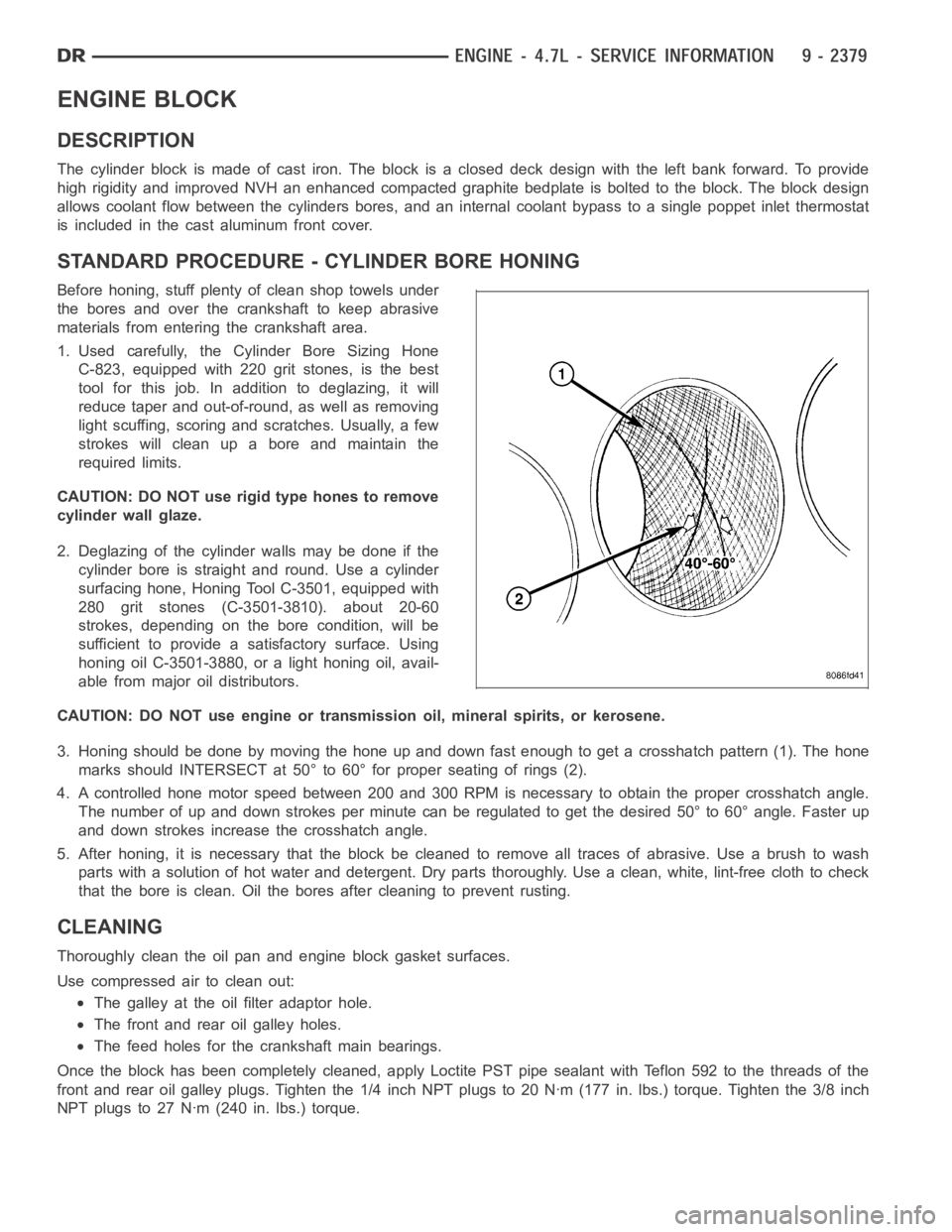
3. Honing should be done by moving the hone up and down fast enough to get a crosshatch pattern (1). The hone
marks should INTERSECT at 50° to 60° for proper seating of rings (2).
4. A controlled hone motor speed between 200 and 300 RPM is necessary to obtain the proper crosshatch angle.
The number of up and down strokes per minute can be regulated to get the desired 50° to 60° angle. Faster up
and down strokes increase the crosshatch angle.
5. After honing, it is necessary that the block be cleaned to remove all traces of abrasive. Use a brush to wash
parts with a solution of hot water and detergent. Dry parts thoroughly. Usea clean, white, lint-free cloth to check
that the bore is clean. Oil the bores after cleaning to prevent rusting.
CLEANING
Thoroughly clean the oil pan and engine block gasket surfaces.
Use compressed air to clean out:
The galley at the oil filter adaptor hole.
The front and rear oil galley holes.
The feed holes for the crankshaft main bearings.
Once the block has been completely cleaned, apply Loctite PST pipe sealantwith Teflon 592 to the threads of the
front and rear oil galley plugs. Tighten the 1/4 inch NPT plugs to 20 Nꞏm (177in. lbs.) torque. Tighten the 3/8 inch
NPT plugs to 27 Nꞏm (240 in. lbs.) torque.