2006 DODGE RAM SRT-10 parking sensors
[x] Cancel search: parking sensorsPage 3015 of 5267

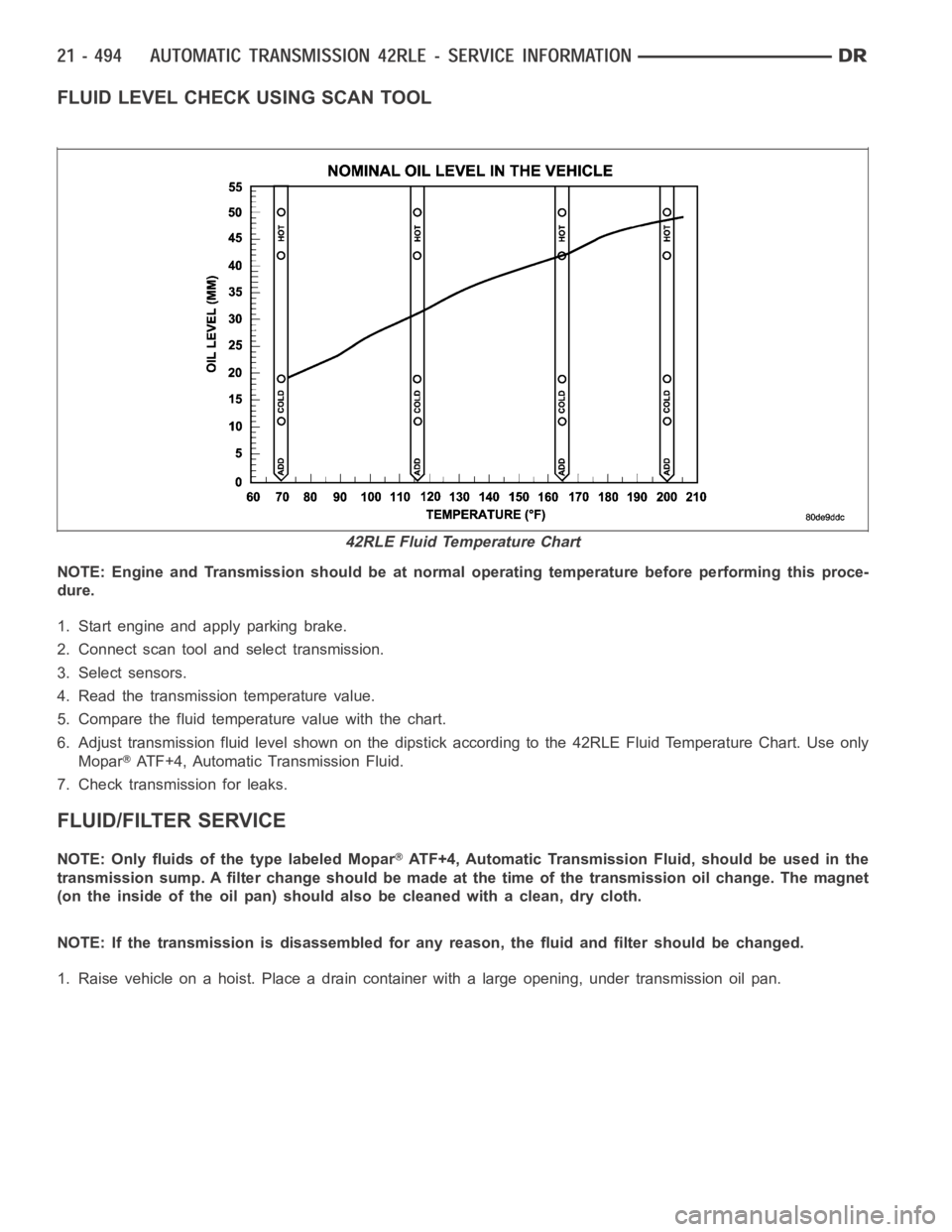
FLUID LEVEL CHECK USING SCAN TOOL
NOTE: Engine and Transmission should be at normal operating temperature before performing this proce-
dure.
1. Start engine and apply parking brake.
2. Connect scan tool and select transmission.
3. Select sensors.
4. Read the transmission temperature value.
5. Compare the fluid temperature value with the chart.
6. Adjust transmission fluid level shown on the dipstick according to the 42RLE Fluid Temperature Chart. Use only
Mopar
ATF+4, Automatic Transmission Fluid.
7. Check transmission for leaks.
FLUID/FILTER SERVICE
NOTE: Only fluids of the type labeled MoparATF+4, Automatic Transmission Fluid, should be used in the
transmission sump. A filter change should be made at the time of the transmission oil change. The magnet
(on the inside of the oil pan) should also be cleaned with a clean, dry cloth.
NOTE: If the transmission is disassembled for any reason, the fluid and filter should be changed.
1. Raise vehicle on a hoist. Place a drain container with a large opening, under transmission oil pan.
42RLE Fluid Temperature Chart
Page 3142 of 5267

When Monitored:
The transmission gear ratio is monitored continuously while the transmission is in gear.
Set Condition:
If there is an excessive change in output RPM in any gear. This DTC can take upto five minutes of problem
identification beforeilluminating the MIL.
Possible Causes
(T14) OUTPUT SPEED SENSOR SIGNAL CIRCUIT OPEN
(T13) SPEED SENSOR GROUND CIRCUIT OPEN
(T14) OUTPUT SPEED SENSOR SIGNAL CIRCUIT SHORT TO GROUND
(T13) SPEED SENSOR GROUND CIRCUIT SHORT TO GROUND
(T14) OUTPUT SPEED SENSOR SIGNAL CIRCUIT SHORT TO VOLTAGE
(T13) SPEED SENSOR GROUND CIRCUIT SHORT TO VOLTAGE
OUTPUT SPEED SENSOR
POWERTRAIN CONTROL MODULE
Always perform the 45RFE/545RFE Pre-Diagnostic Troubleshooting Procedure before proceeding. (Refer to
21 - TRANSMISSION/TRANSAXLE/AUTOMATIC - 45RFE/545RFE - STANDARD PROCEDURE)
Theory of Operation
The transmission system uses two speed sensors, one to measure input RPM and one to measure output RPM.
These inputs are essential for proper transmission operation. Therefore, the integrity of this data is verified through
the following checks:
1) When in gear, if the gear ratio does not compare to a known gear ratio, the corresponding in-gear trouble code
is set (codes P0731 through P0736).
2) An excessive change in input or output speeds indicating signal intermittent will result in codes P0715 and/or
P0720 being set.
3) If the common speed sensor ground circuit is lost, both sensor inputs will read the signal from the input speed
sensor at idle in neutral. Since the input speed sensor has 60 teeth and the output speed sensor has 30 teeth, this
results in a an apparent speed ratio of 1:2 and may cause the DTC P1794 to set.
Diagnostic Test
1.CHECK TO SEE IF DTC P0720 IS CURRENT
Turn the ignition off to the lock position.
CAUTION: Properly support the vehicle and raise all drive wheels off the ground.
Release the parking brake.
Start the engine in park.
Place the transmission gear selector in drive, release foot from brake.
WARNING: Be sure to keep hands and feet clear of rotation wheels.
With the scan tool, monitor the Output Speed Sensor RPM.
Is the Output Speed Sensor RPM below 100 RPM?
Ye s>>
Go To 2
No>>
Go To 9
Page 3431 of 5267

In either case, air bubbles can cause overheating and/or fluid oxidation,and varnishing. This can interfere with nor-
mal valve, clutch, and accumulator operation. Foaming can also result in fluid escaping from the transmission vent
where it may be mistaken for a leak.
After the fluid has been checked, seat the dipstick fully to seal out water and dirt.
The transmission has a dipstick to check oil level. It is located on the right side of the engine. Be sure to wipe all
dirt from dipstick handle before removing.
The torque converter fills in both the P(PARK) and N (NEUTRAL) positions. Place the selector lever in P (PARK)
to be sure that the fluid level check is accurate.The engine should be running at idle speed for at least one
minute, with the vehicle on level ground.At normal operating temperature (approximately 82° C. or 180° F), the
fluid level is correct if it is in the HOT region (cross-hatched area) on theoil level indicator. The fluid level will be
approximately at the upper COLD hole of the dipstick at 21° C (70° F) fluid temperature.
NOTE: Engine and Transmission should be at normal operating temperature before performing this proce-
dure.
1. Start engine and apply parking brake.
2. Shift the transmission into DRIVE for approximately 2 seconds.
3. Shift the transmission into REVERSE for approximately 2 seconds.
4. Shift the transmission into PARK.
5. Hook up scan tool andselect transmission.
6. Select sensors.
7. Read the transmission temperature value.
8. Compare the fluid temperature value with the chart.
9. Adjust transmission fluid level shown on the dipstick according to the Transmission Fluid Temperature Chart.
NOTE: After adding any fluid to the transmission, wait a minimum of 2 minutes for the oil to fully drain from
the fill tube into the transmission before rechecking the fluid level.
10. Check transmission for leaks.
Page 3603 of 5267

Theory of Operation
The Governor Pressure Sensors output is used as a control input to the Governor Pressure Control System. The
Governor Pressure Control System is used to regulate the governor pressure which controls the shifts for first, sec-
ond, and third gear.
When Monitored:
While the engine is running and the vehicle gear selector is in park or neutral for more than 3.0 seconds with
the throttle position less than 10%.
Set Condition:
This DTC will set if the Governor Pressure is greater than 3 psi while the vehicle is in Park 3 times in a drive
cycle.
Possible Causes
OTHER TRANSMISSION DTCS PRESENT
(F856) 5 VOLT SUPPLY CIRCUIT OPEN - EXTERNAL
(F856) 5 VOLT SUPPLY CIRCUIT OPEN - INTERNAL
GOVERNOR PRESSURE SENSOR
TRANSMISSION - INTERNAL DAMAGE
TRANSMISSION - INTERNAL LEAK
POWERTRAIN CONTROL MODULE
INTERMITTENT WIRING AND CONNECTORS
Always perform the Pre-Diagnostic Troubleshooting procedure before proceeding. (Refer to 21 - TRANSMIS-
SION/TRANSAXLE/AUTOMATIC - 48RE - STANDARD PROCEDURE)
Diagnostic Test
1.OTHER TRANSMISSION DTCS PRESENT
Ignition on, engine not running.
With the scan tool, read Engine DTCs.
Are any other transmission DTCs present?
Ye s>>
Refer to the Transmission category and perform the appropriate symptom(s).
No>>
Go To 2
2.CHECK IF THE GOVERNOR PRESSURE IS ABOVE 21 KPA (3 PSI) IN PARK
CAUTION: Apply the parking brake.
Start the engine and allow the engine to idle.
Warm the transmission to a normal operating temperature above 43° C (110° F).
With the scan tool in Sensors, read the Governor Pressure with the Transmission Shift selector in Park.
Is the Governor Pressure reading on the scan tool above 21 kPa or 3 psi?
Ye s>>
Go To 3
No>>
Go To 10
Page 3766 of 5267

Theory of Operation
The Governor Pressure Sensors output is used as a control input to the Governor Pressure Control System. The
Governor Pressure Control System is used to regulate the governor pressure which controls the shifts for first, sec-
ond, and third gear.
When Monitored:
While the engine is running and the vehicle gear selector is in park or neutral for more than 3.0 seconds with
the throttle position less than 10%.
Set Condition:
This DTC will set if the Governor Pressure is greater than 3 psi while the vehicle is in Park 3 times in a drive
cycle.
Possible Causes
OTHER TRANSMISSION DTCS PRESENT
5 VOLT SUPPLY CIRCUIT OPEN - EXTERNAL
5 VOLT SUPPLY CIRCUIT OPEN - INTERNAL
GOVERNOR PRESSURE SENSOR
TRANSMISSION - INTERNAL DAMAGE
TRANSMISSION - INTERNAL LEAK
ENGINE CONTROL MODULE
INTERMITTENT WIRING AND CONNECTORS
Always perform the Pre-Diagnostic Troubleshooting procedure before proceeding. (Refer to 21 - TRANSMIS-
SION/TRANSAXLE/AUTOMATIC - 48RE - STANDARD PROCEDURE)
Diagnostic Test
1.OTHER TRANSMISSION DTCS PRESENT
Ignition on, engine not running.
With the scan tool, read Engine DTCs.
Are any other transmission DTCs present?
Ye s>>
Refer to the Transmission category and perform the appropriate symptom(s).
No>>
Go To 2
2.CHECK IF THE GOVERNOR PRESSURE IS ABOVE 21 KPA (3 PSI) IN PARK
CAUTION: Apply the parking brake.
Start the engine and allow the engine to idle.
Warm the transmission to a normal operating temperature above 43° C (110° F).
With the scan tool in Sensors, read the Governor Pressure with the Transmission Shift selector in Park.
Is the Governor Pressure reading on the scan tool above 21 kPa or 3 psi?
Ye s>>
Go To 3
No>>
Go To 10
Page 3876 of 5267

PROCEDURE TWO
1. Start engine and apply parking brake.
2. Shift the transmission into DRIVE for approximately 2 seconds.
3. Shift the transmission into REVERSE for approximately 2 seconds.
4. Shift the transmission into PARK.
5. Hook up DRB
scan tool and select engine.
6. Select sensors.
7. Read the transmission temperature value.
8. Compare the fluid temperature value with the chart.
9. Adjust transmission fluid level shown on the dipstick according to the chart.
NOTE: After adding any fluid to the transmission, wait a minimum of 2 minutes for the oil to fully drain from
the fill tube into the transmission before rechecking the fluid level.
10. Check transmission for leaks.
FLUID AND FILTER REPLACEMENT
For proper service intervals (Refer to LUBRICATION & MAINTENANCE/MAINTENANCE SCHEDULES - DESCRIP-
TION). The service fluid fill after a filter change is approximately 3.8 liters (4.0 quarts).